EP0486956A1 - Boîtier pour composants électriques ou électroniques - Google Patents
Boîtier pour composants électriques ou électroniques Download PDFInfo
- Publication number
- EP0486956A1 EP0486956A1 EP91119493A EP91119493A EP0486956A1 EP 0486956 A1 EP0486956 A1 EP 0486956A1 EP 91119493 A EP91119493 A EP 91119493A EP 91119493 A EP91119493 A EP 91119493A EP 0486956 A1 EP0486956 A1 EP 0486956A1
- Authority
- EP
- European Patent Office
- Prior art keywords
- housing
- connecting element
- pin
- hinge
- parts
- Prior art date
- Legal status (The legal status is an assumption and is not a legal conclusion. Google has not performed a legal analysis and makes no representation as to the accuracy of the status listed.)
- Granted
Links
Images
Classifications
-
- H—ELECTRICITY
- H02—GENERATION; CONVERSION OR DISTRIBUTION OF ELECTRIC POWER
- H02G—INSTALLATION OF ELECTRIC CABLES OR LINES, OR OF COMBINED OPTICAL AND ELECTRIC CABLES OR LINES
- H02G3/00—Installations of electric cables or lines or protective tubing therefor in or on buildings, equivalent structures or vehicles
- H02G3/02—Details
- H02G3/08—Distribution boxes; Connection or junction boxes
- H02G3/14—Fastening of cover or lid to box
-
- E—FIXED CONSTRUCTIONS
- E05—LOCKS; KEYS; WINDOW OR DOOR FITTINGS; SAFES
- E05D—HINGES OR SUSPENSION DEVICES FOR DOORS, WINDOWS OR WINGS
- E05D11/00—Additional features or accessories of hinges
- E05D11/10—Devices for preventing movement between relatively-movable hinge parts
- E05D11/1007—Devices for preventing movement between relatively-movable hinge parts with positive locking
-
- H—ELECTRICITY
- H02—GENERATION; CONVERSION OR DISTRIBUTION OF ELECTRIC POWER
- H02B—BOARDS, SUBSTATIONS OR SWITCHING ARRANGEMENTS FOR THE SUPPLY OR DISTRIBUTION OF ELECTRIC POWER
- H02B1/00—Frameworks, boards, panels, desks, casings; Details of substations or switching arrangements
- H02B1/015—Boards, panels, desks; Parts thereof or accessories therefor
- H02B1/06—Boards, panels, desks; Parts thereof or accessories therefor having associated enclosures, e.g. for preventing access to live parts
-
- E—FIXED CONSTRUCTIONS
- E05—LOCKS; KEYS; WINDOW OR DOOR FITTINGS; SAFES
- E05Y—INDEXING SCHEME ASSOCIATED WITH SUBCLASSES E05D AND E05F, RELATING TO CONSTRUCTION ELEMENTS, ELECTRIC CONTROL, POWER SUPPLY, POWER SIGNAL OR TRANSMISSION, USER INTERFACES, MOUNTING OR COUPLING, DETAILS, ACCESSORIES, AUXILIARY OPERATIONS NOT OTHERWISE PROVIDED FOR, APPLICATION THEREOF
- E05Y2900/00—Application of doors, windows, wings or fittings thereof
- E05Y2900/20—Application of doors, windows, wings or fittings thereof for furniture, e.g. cabinets
-
- E—FIXED CONSTRUCTIONS
- E05—LOCKS; KEYS; WINDOW OR DOOR FITTINGS; SAFES
- E05Y—INDEXING SCHEME ASSOCIATED WITH SUBCLASSES E05D AND E05F, RELATING TO CONSTRUCTION ELEMENTS, ELECTRIC CONTROL, POWER SUPPLY, POWER SIGNAL OR TRANSMISSION, USER INTERFACES, MOUNTING OR COUPLING, DETAILS, ACCESSORIES, AUXILIARY OPERATIONS NOT OTHERWISE PROVIDED FOR, APPLICATION THEREOF
- E05Y2999/00—Subject-matter not otherwise provided for in this subclass
Definitions
- the invention relates to a housing, in particular for receiving electrical or electronic components, consisting of an upper and a lower part and a connecting element between the upper and lower part, which firmly connects the two parts to one another in a first pivoting position and in a second position pivoted to this end releases the parts.
- toggle closures In known housings of this type, connecting elements are provided, which are known as so-called toggle closures. These toggle fasteners allow a quick connection between the upper part of the housing and the lower part of the housing. Such toggle closures are used both in housings whose lids are placed on the base part and in housings whose lids are hinged to the base part. Housing, the lid of which can be folded on the base part are hinged, in addition to the connecting elements between the cover and the base part, hinges between these two parts.
- the invention is based on the object of designing a housing of the type presumed to be known, or its connecting element, in such a way that the connecting element both for establishing a fixed connection between the upper and lower part and for establishing a pivoting connection between the upper and lower part. and lower part can be used.
- connecting element hingedly connects the two parts to one another in at least one further third defined pivoting position.
- the connecting element has two hinge halves which are connected to one another via a hinge pin running transversely to its pivot axis. With such a connecting element, the hinge is therefore built into the connecting element.
- the connecting element has a flange which extends transversely to its longitudinal pivot axis and has a first socket which partially engages around a pin fixed to the housing and extending in the hinge axis direction.
- Hinge formed by the connecting element and one of the housing parts.
- the housing according to the invention makes it possible to completely dispense with the provision of a hinge between the upper housing part and the lower housing part.
- the connecting element and its swivel position make it possible to choose different functions of the housing.
- the user therefore reserves the right to fold the lid if necessary or to remove it freely.
- the folding axles can be freely selected in the foldable articulation state.
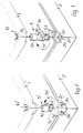
- the drawing shows a corner area of a lower part 2 and an upper part 1 of a housing.
- the upper part 1 is connected to the lower part 2 via the connecting element 3, which is shown in one piece, but also has to be formed in several parts.
- the upper part 1 has an inlet opening 1a in the corner region, in which the head 3a of the connecting element lies in the assembled state.
- the head part 3a of the connecting element is adjoined by two hinge halves 3b and 3c, which are connected to one another via a hinge pin 3e.
- On the hinge half 3c sits the shaft 3d, which has radially extending pin-like projections 3f transverse to the pivot axis 3g.
- a housing part 2c is provided in the corner area, which has a round through opening with four radially widening recesses 2b.
- the through opening 2a and the radial extensions are designed so that the shaft 3d and the pin-like projections can dive through these openings in a corresponding pivoting drawer.
- the connecting element 3 is pivotally attached to the upper part 1.
- the connecting element 3 is pivoted by 45 ° relative to the position shown, so that the pin-like projections 3f are aligned with the recesses 2b.
- the connecting element is then pressed down in this position while overcoming a restoring or spring force and by 45 ° either pivoted into the position shown in Figure 1 or in a position rotated by 90 °.
- the upper part 1 is connected to the lower part 2 about a pivot axis which runs parallel to one of the two mutually perpendicular sides.
- the restoring force mentioned which must be overcome before pivoting, can be generated in different ways.
- the upper part 1 ' has an inlet opening 1a' in which the head 3a 'of the connecting element 3' lies.
- the head 3a ' is followed by a stepped shaft 3e', at the lower end of which a flange 3b 'extending transversely to the pivot axis 3g' is provided.
- the flange 3b ' has two channel-like pans 3c' and 3d 'running parallel to one another.
- the two pans 3c 'and 3d' run parallel to each other and are laterally offset from the pivot axis 3g '.
- the socket 3c ' engages under a first housing-fixed pin 2a' of the lower part 2 '.
- the upper part 1 ' is pivotally articulated about the central axis of the pin 2a' on the lower part 2 '.
- the second pan 3d ' engages under the second housing-fixed pin 2b'.
- the upper part 1 ' is pivotably articulated about the axis on the lower part 2' which corresponds to the central axis of the second housing-fixed pin 2b '.
- elasticity between the upper part and the lower part or between the connecting element 3 'and the lower part 2' is also necessary in this embodiment.
- this elasticity can be generated, for example, by the elasticity of the seal between lower part 2 'and upper part 1'.
- it is also possible to produce the elasticity by providing a compression spring below the head 3a ', which is supported on the corresponding area of the inlet opening 1a' and thus on the upper part 1 '.
- a compression spring not shown, always pushes the head 3a 'upwards. In the same way, the pans 3c 'or 3d' are pressed from below against the associated pins 2a 'or 2b'.
- the folding axes are preferably arranged in all embodiments so that they lie in the extension of the outer surfaces of the housing.
- the central axis of the first pin 2a fixed to the housing lies in the extension of the outer contour of the longitudinal side of the lower part 2 '.
- the central axis of the second pin 2b 'fixed to the housing lies in the extension of the outer contour of the transverse side of the lower part 2'.
Landscapes
- Engineering & Computer Science (AREA)
- Power Engineering (AREA)
- Architecture (AREA)
- Civil Engineering (AREA)
- Structural Engineering (AREA)
- Mechanical Engineering (AREA)
- Casings For Electric Apparatus (AREA)
Applications Claiming Priority (2)
| Application Number | Priority Date | Filing Date | Title |
|---|---|---|---|
| DE4037063 | 1990-11-22 | ||
| DE4037063A DE4037063A1 (de) | 1990-11-22 | 1990-11-22 | Gehaeuse, insbesondere zur aufnahme von elektrischen oder elektronischen bauelementen |
Publications (2)
| Publication Number | Publication Date |
|---|---|
| EP0486956A1 true EP0486956A1 (fr) | 1992-05-27 |
| EP0486956B1 EP0486956B1 (fr) | 1994-12-28 |
Family
ID=6418670
Family Applications (1)
| Application Number | Title | Priority Date | Filing Date |
|---|---|---|---|
| EP91119493A Expired - Lifetime EP0486956B1 (fr) | 1990-11-22 | 1991-11-15 | Boîtier pour composants électriques ou électroniques |
Country Status (2)
| Country | Link |
|---|---|
| EP (1) | EP0486956B1 (fr) |
| DE (2) | DE4037063A1 (fr) |
Cited By (1)
| Publication number | Priority date | Publication date | Assignee | Title |
|---|---|---|---|---|
| EP2632004A1 (fr) * | 2012-02-22 | 2013-08-28 | Berker GmbH & Co. KG | Appareil électrique muni d'un insert pour la fixation du couvercle |
Families Citing this family (2)
| Publication number | Priority date | Publication date | Assignee | Title |
|---|---|---|---|---|
| FR2866193B1 (fr) * | 2004-02-10 | 2006-03-24 | Schneider Electric Ind Sas | Boite a coins etanches |
| DE602005007394D1 (de) * | 2004-02-10 | 2008-07-24 | Schneider Electric Ind Sas | Metallgehäuse, insbesondere für elektrische Geräte |
Citations (6)
| Publication number | Priority date | Publication date | Assignee | Title |
|---|---|---|---|---|
| US2744654A (en) * | 1954-05-10 | 1956-05-08 | Gen Electric | Closure fastener and hinge construction |
| GB801919A (en) * | 1957-05-25 | 1958-09-24 | Automatic Telephone & Elect | Improvements in or relating to electrical equipment mounting racks |
| CH403003A (de) * | 1962-11-07 | 1965-11-30 | Bbc Brown Boveri & Cie | Schnellverschluss zwischen Deckel und Gehäuse elektrischer Apparate |
| CA893357A (en) * | 1970-06-11 | 1972-02-15 | Cascade Electronics Ltd. | Housing for electrical equipment |
| DE2447763A1 (de) * | 1974-10-07 | 1976-04-15 | Fiskars Ab Oy | Installationsbuechse fuer installation und isolierung von elektrischen leitungen und zubehoer |
| EP0202565A1 (fr) * | 1985-05-16 | 1986-11-26 | GEWISS S.p.A. | Dispositif de fermeture fonctionnant comme une charnière pour coffret de composants électroniques |
Family Cites Families (6)
| Publication number | Priority date | Publication date | Assignee | Title |
|---|---|---|---|---|
| US4391461A (en) * | 1980-10-16 | 1983-07-05 | Tektronix, Inc. | Quarter-turn fastener |
| DE3543989A1 (de) * | 1985-12-12 | 1987-06-19 | Siemens Ag | Schwenkvorrichtung fuer einen gehaeusedeckel |
| DE3624347C1 (de) * | 1986-07-16 | 1987-11-12 | Krone Ag | Gehaeuse,insbesondere Verteilergehaeuse fuer die Fernmeldetechnik |
| SE460167B (sv) * | 1987-04-07 | 1989-09-11 | Dresser Wayne Ab | Instrumentskaap |
| DE8713225U1 (de) * | 1987-10-01 | 1987-12-03 | Bündoplast bopla Gehäuse Systeme GmbH, 4980 Bünde | Gehäuse |
| DE8812055U1 (de) * | 1988-09-22 | 1990-01-25 | Ramsauer, Dieter, 42555 Velbert | Scharnierstift |
-
1990
- 1990-11-22 DE DE4037063A patent/DE4037063A1/de not_active Withdrawn
-
1991
- 1991-11-15 EP EP91119493A patent/EP0486956B1/fr not_active Expired - Lifetime
- 1991-11-15 DE DE59104067T patent/DE59104067D1/de not_active Expired - Fee Related
Patent Citations (6)
| Publication number | Priority date | Publication date | Assignee | Title |
|---|---|---|---|---|
| US2744654A (en) * | 1954-05-10 | 1956-05-08 | Gen Electric | Closure fastener and hinge construction |
| GB801919A (en) * | 1957-05-25 | 1958-09-24 | Automatic Telephone & Elect | Improvements in or relating to electrical equipment mounting racks |
| CH403003A (de) * | 1962-11-07 | 1965-11-30 | Bbc Brown Boveri & Cie | Schnellverschluss zwischen Deckel und Gehäuse elektrischer Apparate |
| CA893357A (en) * | 1970-06-11 | 1972-02-15 | Cascade Electronics Ltd. | Housing for electrical equipment |
| DE2447763A1 (de) * | 1974-10-07 | 1976-04-15 | Fiskars Ab Oy | Installationsbuechse fuer installation und isolierung von elektrischen leitungen und zubehoer |
| EP0202565A1 (fr) * | 1985-05-16 | 1986-11-26 | GEWISS S.p.A. | Dispositif de fermeture fonctionnant comme une charnière pour coffret de composants électroniques |
Cited By (1)
| Publication number | Priority date | Publication date | Assignee | Title |
|---|---|---|---|---|
| EP2632004A1 (fr) * | 2012-02-22 | 2013-08-28 | Berker GmbH & Co. KG | Appareil électrique muni d'un insert pour la fixation du couvercle |
Also Published As
| Publication number | Publication date |
|---|---|
| DE4037063A1 (de) | 1992-05-27 |
| DE59104067D1 (de) | 1995-02-09 |
| EP0486956B1 (fr) | 1994-12-28 |
Similar Documents
| Publication | Publication Date | Title |
|---|---|---|
| DE69610866T2 (de) | Scharniervorrichtung | |
| DE69108995T2 (de) | Aus zwei über ein Gelenk und elektrisch verbundenen Elementen bestehendes Gerät. | |
| DE3889821T2 (de) | Tragbares Gehäuse mit einem klappbaren Griff. | |
| DE69621920T2 (de) | Faltbares werkzeug | |
| EP0499809B1 (fr) | Chaîne porteuse pour lignes de transport d'énergie | |
| DE19707629A1 (de) | Scharnier | |
| DE2905138A1 (de) | Wischblatt mit einem tragbuegelsystem | |
| DE3802678A1 (de) | Gehaeuse mit unsichtbarem gelenk | |
| DE68908585T2 (de) | Bi-stabile Gelenkvorrichtung aus elastischem Material. | |
| DE2824216A1 (de) | Betaetigungsvorrichtung fuer einen tuerverschluss, insbesondere innenbetaetigungsvorrichtung fuer einen kraftfahrzeug-tuerverschluss | |
| DE10301147A1 (de) | Scharniereinrichtung mit Rasteigenschaft | |
| DE60200220T2 (de) | Elektrischer Steckanschluss mit Verschlussbuchsenblenden und Baureihe mit einem solchen Steckanschluss | |
| EP0486956B1 (fr) | Boîtier pour composants électriques ou électroniques | |
| CH674670A5 (en) | Swivel arm fixed to desk | |
| DE9419608U1 (de) | Gelenkglied | |
| EP0230259A2 (fr) | Boîtier en forme de parallélépipède pour objets | |
| EP0563598B1 (fr) | Boîtier pour le montage de composants et assemblages électriques ou électroniques | |
| DE3874729T2 (de) | Scharnier. | |
| DE4035506C2 (de) | Gehäuse für ein elektrisches Gerät | |
| DE3637244A1 (de) | Scharnier | |
| DE3511901C2 (fr) | ||
| EP0310004A2 (fr) | Boîtier | |
| EP0198224B1 (fr) | Boîtier | |
| DE9410602U1 (de) | Steckverbinder mit einem Schwenkhebel zur Verriegelung zweier Steckergehäuse | |
| DE202021106714U1 (de) | Halterung für Fahrradzubehör |
Legal Events
| Date | Code | Title | Description |
|---|---|---|---|
| PUAI | Public reference made under article 153(3) epc to a published international application that has entered the european phase |
Free format text: ORIGINAL CODE: 0009012 |
|
| AK | Designated contracting states |
Kind code of ref document: A1 Designated state(s): CH DE DK FR GB IT LI NL |
|
| 17P | Request for examination filed |
Effective date: 19920424 |
|
| 17Q | First examination report despatched |
Effective date: 19930621 |
|
| GRAA | (expected) grant |
Free format text: ORIGINAL CODE: 0009210 |
|
| AK | Designated contracting states |
Kind code of ref document: B1 Designated state(s): CH DE DK FR GB IT LI NL |
|
| PG25 | Lapsed in a contracting state [announced via postgrant information from national office to epo] |
Ref country code: IT Free format text: LAPSE BECAUSE OF FAILURE TO SUBMIT A TRANSLATION OF THE DESCRIPTION OR TO PAY THE FEE WITHIN THE PRE;WARNING: LAPSES OF ITALIAN PATENTS WITH EFFECTIVE DATE BEFORE 2007 MAY HAVE OCCURRED AT ANY TIME BEFORE 2007. THE CORRECT EFFECTIVE DATE MAY BE DIFFERENT FROM THE ONE RECORDED.SCRIBED TIME-LIMIT Effective date: 19941228 Ref country code: GB Effective date: 19941228 Ref country code: DK Effective date: 19941228 Ref country code: NL Effective date: 19941228 Ref country code: FR Effective date: 19941228 |
|
| REF | Corresponds to: |
Ref document number: 59104067 Country of ref document: DE Date of ref document: 19950209 |
|
| EN | Fr: translation not filed | ||
| NLV1 | Nl: lapsed or annulled due to failure to fulfill the requirements of art. 29p and 29m of the patents act | ||
| GBV | Gb: ep patent (uk) treated as always having been void in accordance with gb section 77(7)/1977 [no translation filed] |
Effective date: 19941228 |
|
| PLBE | No opposition filed within time limit |
Free format text: ORIGINAL CODE: 0009261 |
|
| STAA | Information on the status of an ep patent application or granted ep patent |
Free format text: STATUS: NO OPPOSITION FILED WITHIN TIME LIMIT |
|
| PG25 | Lapsed in a contracting state [announced via postgrant information from national office to epo] |
Ref country code: LI Effective date: 19951130 Ref country code: CH Effective date: 19951130 |
|
| 26N | No opposition filed | ||
| REG | Reference to a national code |
Ref country code: CH Ref legal event code: PL |
|
| PGFP | Annual fee paid to national office [announced via postgrant information from national office to epo] |
Ref country code: DE Payment date: 20071019 Year of fee payment: 17 |
|
| PG25 | Lapsed in a contracting state [announced via postgrant information from national office to epo] |
Ref country code: DE Free format text: LAPSE BECAUSE OF NON-PAYMENT OF DUE FEES Effective date: 20090603 |