EP0486975A1 - Joint de culasse avec anneau de feu revêtu - Google Patents
Joint de culasse avec anneau de feu revêtu Download PDFInfo
- Publication number
- EP0486975A1 EP0486975A1 EP91119569A EP91119569A EP0486975A1 EP 0486975 A1 EP0486975 A1 EP 0486975A1 EP 91119569 A EP91119569 A EP 91119569A EP 91119569 A EP91119569 A EP 91119569A EP 0486975 A1 EP0486975 A1 EP 0486975A1
- Authority
- EP
- European Patent Office
- Prior art keywords
- cylinder head
- head gasket
- gasket according
- sliding coating
- soft material
- Prior art date
- Legal status (The legal status is an assumption and is not a legal conclusion. Google has not performed a legal analysis and makes no representation as to the accuracy of the status listed.)
- Withdrawn
Links
- 238000002485 combustion reaction Methods 0.000 title claims abstract description 12
- 239000011248 coating agent Substances 0.000 claims abstract description 38
- 238000000576 coating method Methods 0.000 claims abstract description 38
- 239000007779 soft material Substances 0.000 claims abstract description 37
- 239000000463 material Substances 0.000 claims abstract description 36
- 229910052751 metal Inorganic materials 0.000 claims abstract description 28
- 239000002184 metal Substances 0.000 claims abstract description 28
- 229910052961 molybdenite Inorganic materials 0.000 claims description 6
- CWQXQMHSOZUFJS-UHFFFAOYSA-N molybdenum disulfide Chemical compound S=[Mo]=S CWQXQMHSOZUFJS-UHFFFAOYSA-N 0.000 claims description 6
- 229910052982 molybdenum disulfide Inorganic materials 0.000 claims description 6
- 239000004810 polytetrafluoroethylene Substances 0.000 claims description 6
- 229920001343 polytetrafluoroethylene Polymers 0.000 claims description 6
- OKTJSMMVPCPJKN-UHFFFAOYSA-N Carbon Chemical compound [C] OKTJSMMVPCPJKN-UHFFFAOYSA-N 0.000 claims description 4
- 239000011230 binding agent Substances 0.000 claims description 4
- 229910002804 graphite Inorganic materials 0.000 claims description 4
- 239000010439 graphite Substances 0.000 claims description 4
- 229920005989 resin Polymers 0.000 claims description 2
- 239000011347 resin Substances 0.000 claims description 2
- 229920001187 thermosetting polymer Polymers 0.000 claims description 2
- 239000000126 substance Substances 0.000 claims 1
- 239000010410 layer Substances 0.000 description 6
- 230000006378 damage Effects 0.000 description 5
- 238000004519 manufacturing process Methods 0.000 description 5
- 238000010276 construction Methods 0.000 description 4
- 229910001060 Gray iron Inorganic materials 0.000 description 3
- 230000002745 absorbent Effects 0.000 description 2
- 239000002250 absorbent Substances 0.000 description 2
- 229910052782 aluminium Inorganic materials 0.000 description 2
- XAGFODPZIPBFFR-UHFFFAOYSA-N aluminium Chemical compound [Al] XAGFODPZIPBFFR-UHFFFAOYSA-N 0.000 description 2
- 238000007688 edging Methods 0.000 description 2
- 239000002245 particle Substances 0.000 description 2
- 239000011148 porous material Substances 0.000 description 2
- 230000001681 protective effect Effects 0.000 description 2
- 230000003746 surface roughness Effects 0.000 description 2
- 230000002195 synergetic effect Effects 0.000 description 2
- 229910000838 Al alloy Inorganic materials 0.000 description 1
- 238000005266 casting Methods 0.000 description 1
- 239000000567 combustion gas Substances 0.000 description 1
- 238000011161 development Methods 0.000 description 1
- 230000018109 developmental process Effects 0.000 description 1
- 238000006073 displacement reaction Methods 0.000 description 1
- 238000000034 method Methods 0.000 description 1
- 239000000843 powder Substances 0.000 description 1
- 238000003825 pressing Methods 0.000 description 1
- 238000007639 printing Methods 0.000 description 1
- 230000003014 reinforcing effect Effects 0.000 description 1
- 238000005096 rolling process Methods 0.000 description 1
- 238000007650 screen-printing Methods 0.000 description 1
- 238000007789 sealing Methods 0.000 description 1
- 239000003566 sealing material Substances 0.000 description 1
- 238000007767 slide coating Methods 0.000 description 1
- 239000012791 sliding layer Substances 0.000 description 1
- 239000007787 solid Substances 0.000 description 1
- 238000005507 spraying Methods 0.000 description 1
Images
Classifications
-
- F—MECHANICAL ENGINEERING; LIGHTING; HEATING; WEAPONS; BLASTING
- F16—ENGINEERING ELEMENTS AND UNITS; GENERAL MEASURES FOR PRODUCING AND MAINTAINING EFFECTIVE FUNCTIONING OF MACHINES OR INSTALLATIONS; THERMAL INSULATION IN GENERAL
- F16J—PISTONS; CYLINDERS; SEALINGS
- F16J15/00—Sealings
- F16J15/02—Sealings between relatively-stationary surfaces
- F16J15/06—Sealings between relatively-stationary surfaces with solid packing compressed between sealing surfaces
- F16J15/10—Sealings between relatively-stationary surfaces with solid packing compressed between sealing surfaces with non-metallic packing
- F16J15/12—Sealings between relatively-stationary surfaces with solid packing compressed between sealing surfaces with non-metallic packing with metal reinforcement or covering
- F16J15/121—Sealings between relatively-stationary surfaces with solid packing compressed between sealing surfaces with non-metallic packing with metal reinforcement or covering with metal reinforcement
- F16J15/122—Sealings between relatively-stationary surfaces with solid packing compressed between sealing surfaces with non-metallic packing with metal reinforcement or covering with metal reinforcement generally parallel to the surfaces
- F16J15/123—Details relating to the edges of the packing
Definitions
- the invention relates to a cylinder head gasket of the type specified in claim 1.
- the metal flange in the area of the combustion chamber opening serves to protect the soft material of the flat gasket base body from the high temperatures occurring there and the combustion gases flowing there.
- this metallic protective edging of the soft material locally high surface pressures can be achieved on the seal.
- damage to the cylinder head gasket in question occurs after a relatively short running time, namely damage in the form of breaks in the metal flange or damage in the form of tearing of the soft material of the flat gasket base body.
- bimetallic constructions are often used, in which the engine block is made of gray cast iron and the cylinder head is made of one Aluminum alloy or vice versa. Such bimetallic constructions prove to be disadvantageous for the cylinder head gasket of the type in question arranged between the engine block and the cylinder head because different material properties meet in the area of the cylinder head gasket due to the material pairing.
- the different strength, the different modulus of elasticity and the different coefficient of linear expansion of the materials used in bimetallic constructions are 0.000024 and that of gray cast iron is 0.0000131.
- a bimetallic construction made of aluminum and gray cast iron results in length differences of up to 0.5 mm between the components, depending on the design, whereby the cylinder head gasket arranged between the components of different materials must allow such length differences without damaging the seal or destroyed and thus leaking.
- the flaring of the combustion chamber opening also occurs a pressing of the soft material between the binding legs of the metal flange is connected, between the metal flange and the soft material tensions.
- These tensions are partially compensated for by the assembly in the engine, but on the other hand increased due to warpage of the engine components and further deformation of the sealing material as well as the thermally induced setting behavior of the seal. This can also cause the gasket to tear and the metallic flare to break.
- the invention has for its object to provide a cylinder head gasket of the type mentioned, which is better able to withstand the stresses during manufacture and in the intended use in engines in favor of longer service lives.
- the invention consists in a slidable connection of the metal flange with the soft material of the flat sealing base body.
- This lubricious connection is achieved in that the contact surface of at least one of the two skirt legs is coated with the soft material.
- the sliding coating is advantageously provided on both edging legs of the U-shaped metal flange.
- a coating is basically only required in the contact area between the skirt legs and soft material. For manufacturing reasons, however, a full-surface coating of one side of the metal strip is preferably carried out, which is provided for the flanging of the combustion chamber opening.
- different soft material materials or different materials for the metal flare are used for the production of the cylinder head gasket in question.
- These different materials each require a material material for the sliding coating in order to ensure sufficient sliding displaceability of the interconnected parts.
- the structure and the layer thickness of the sliding coating have to be adapted to the surface properties of the base body.
- Different soft material materials require a suitable coating material depending on the surface quality, ie depending on the free pore volume and pore cross-section, namely a material that is adapted to the respective surface quality in terms of particle size and layer thickness.
- an absorbent soft material needs a coating that consists of larger solid particles than a coating for a less absorbent soft material.
- the layer thickness of the sliding coating has to be adapted to the surface roughness of the soft material. Ie that with a large surface roughness of the soft material, the layer thickness of the sliding coating must be designed accordingly large.
- Different soft material materials and different materials of the metal flange are advantageously taken into account by a combination of different coating materials.
- advantageous coating materials come into question MoS2, graphite or PTFE. If these materials are in powder form, they require the addition of a high-temperature-resistant binder in order to ensure the necessary adhesion of the sliding coating to the binding legs of the metal flange.
- Hardening thermosetting resins are particularly suitable as binders.
- the combination of different materials can be advantageous for the sliding coating.
- MoS2 and PTFE at the same time, there is an advantageous synergistic effect because MoS2 slides well on the surface of the metal flange, while the softer PTFE is better able to fill the rough soft material surface.
- thin layer thicknesses of the sliding coating can be achieved by rolling, casting or printing, in particular screen printing. Larger layer thicknesses can be achieved, for example, by multiple spraying.
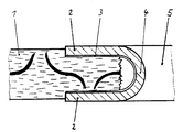
- the cylinder head gasket shown consists of a flat base body 1 made of soft material, into which reinforcing inserts with a serrated cross section are introduced.
- the combustion chamber opening 5 of the cylinder head gasket shown is edged with a U-shaped metal flange.
- the soft material of the base body 1 is thus enclosed in the area of the combustion chamber opening by the two binding legs 2 of the U-shaped metal flange, which are connected to one another via a flange nose 4, which corresponds to the curvature area of the U-shaped metal flange.
- the circumferential U-shaped metal flange is provided with a sliding coating 3 on the inside. Due to the sliding coating 3, the soft material of the base body 1 is not in direct contact with the material of the U-shaped metal flange. Rather, this contact takes place with the interposition of the sliding coating 3, which has sliding properties with respect to the soft material.
- the thickness of the sliding coating 3 is selected so that the rough surface of the soft material material in the region of the skirt legs 2 is completely filled in favor of good sliding properties.
- the sliding coating 3 for example MoS2, graphite or PTFE comes into question.
- the materials for the sliding coating 3 are selected on the basis of the respective requirements, that is to say taking into account the pressures to be expected and the high temperatures when the cylinder head gasket is used as intended.
- PTFE is less suitable for the sliding coating 3 due to its weaker structural strength.
- MoS2 or graphite is more suitable, for example.
- the advantage of the sliding coating 3 is that tensions between the soft material and the metal flange can be compensated for by a relative displacement of these two materials to one another, whereby an increased stability of the cylinder head gasket is achieved compared to conventional cylinder head gaskets without such a sliding coating between the soft material and the metal flange , because the risk of tearing the soft material and the risk of the metal flange breaking is significantly reduced.
- the soft material of the flat base body 1 can in principle also be provided with the sliding coating 3.
- the only decisive factor is that a suitable sliding layer is present at all between the soft material and the metal flange.
Landscapes
- Engineering & Computer Science (AREA)
- General Engineering & Computer Science (AREA)
- Mechanical Engineering (AREA)
- Gasket Seals (AREA)
Applications Claiming Priority (2)
| Application Number | Priority Date | Filing Date | Title |
|---|---|---|---|
| DE4036871 | 1990-11-19 | ||
| DE4036871A DE4036871C2 (de) | 1990-11-19 | 1990-11-19 | Zylinderkopfdichtung mit beschichteter Metalleinfassung des Brennraumdurchbruchs |
Publications (1)
| Publication Number | Publication Date |
|---|---|
| EP0486975A1 true EP0486975A1 (fr) | 1992-05-27 |
Family
ID=6418567
Family Applications (1)
| Application Number | Title | Priority Date | Filing Date |
|---|---|---|---|
| EP91119569A Withdrawn EP0486975A1 (fr) | 1990-11-19 | 1991-11-15 | Joint de culasse avec anneau de feu revêtu |
Country Status (2)
| Country | Link |
|---|---|
| EP (1) | EP0486975A1 (fr) |
| DE (1) | DE4036871C2 (fr) |
Cited By (3)
| Publication number | Priority date | Publication date | Assignee | Title |
|---|---|---|---|---|
| EP0974630A1 (fr) * | 1998-07-22 | 2000-01-26 | Reinz-Dichtungs-Gmbh | Matériau de revêtement thermodurcissable applicable sans solvant |
| US6346997B1 (en) | 1993-12-24 | 2002-02-12 | Canon Kabushiki Kaisha | Illumination device, image reading apparatus having the device and information processing system having the apparatus |
| EP3290754A1 (fr) | 2016-08-30 | 2018-03-07 | Frenzelit Werke GmbH | Produit d'etancheite compressible a bordure |
Families Citing this family (1)
| Publication number | Priority date | Publication date | Assignee | Title |
|---|---|---|---|---|
| DE19713053C2 (de) * | 1997-03-27 | 1999-01-28 | Reinz Dichtungs Gmbh | Flachdichtung mit Gleiteigenschaften aufweisender Oberfläche |
Citations (4)
| Publication number | Priority date | Publication date | Assignee | Title |
|---|---|---|---|---|
| DE2019477A1 (de) * | 1970-04-22 | 1971-11-11 | Reinz Dichtung Gmbh | Flachdichtung,insbesondere fuer Verbrennungsmotoren |
| GB2091824A (en) * | 1981-01-22 | 1982-08-04 | Goetze Ag | Flat gaskets |
| EP0214377A1 (fr) * | 1985-08-09 | 1987-03-18 | Goetze Ag | Joint d'étanchéité plat, notamment joint de culasse pour moteur à combustion interne |
| DE3905922A1 (de) * | 1989-02-25 | 1990-08-30 | Goetze Ag | Flachdichtung, insbesondere zylinderkopfdichtung |
Family Cites Families (3)
| Publication number | Priority date | Publication date | Assignee | Title |
|---|---|---|---|---|
| DE3423787A1 (de) * | 1984-06-28 | 1986-02-13 | Elring Dichtungswerke Gmbh, 7012 Fellbach | Zylinderkopfdichtung |
| DE3618786A1 (de) * | 1986-06-04 | 1987-12-10 | Goetze Ag | Flachdichtung, insbesondere fuer verbrennungskraftmaschinen |
| DE8620859U1 (de) * | 1986-08-02 | 1986-11-27 | Goetze Ag, 5093 Burscheid | Imprägnierte Flachdichtung, insbesondere Zylinderkopfdichtung für Verbrennungskraftmaschinen |
-
1990
- 1990-11-19 DE DE4036871A patent/DE4036871C2/de not_active Expired - Fee Related
-
1991
- 1991-11-15 EP EP91119569A patent/EP0486975A1/fr not_active Withdrawn
Patent Citations (4)
| Publication number | Priority date | Publication date | Assignee | Title |
|---|---|---|---|---|
| DE2019477A1 (de) * | 1970-04-22 | 1971-11-11 | Reinz Dichtung Gmbh | Flachdichtung,insbesondere fuer Verbrennungsmotoren |
| GB2091824A (en) * | 1981-01-22 | 1982-08-04 | Goetze Ag | Flat gaskets |
| EP0214377A1 (fr) * | 1985-08-09 | 1987-03-18 | Goetze Ag | Joint d'étanchéité plat, notamment joint de culasse pour moteur à combustion interne |
| DE3905922A1 (de) * | 1989-02-25 | 1990-08-30 | Goetze Ag | Flachdichtung, insbesondere zylinderkopfdichtung |
Cited By (4)
| Publication number | Priority date | Publication date | Assignee | Title |
|---|---|---|---|---|
| US6346997B1 (en) | 1993-12-24 | 2002-02-12 | Canon Kabushiki Kaisha | Illumination device, image reading apparatus having the device and information processing system having the apparatus |
| EP0974630A1 (fr) * | 1998-07-22 | 2000-01-26 | Reinz-Dichtungs-Gmbh | Matériau de revêtement thermodurcissable applicable sans solvant |
| EP3290754A1 (fr) | 2016-08-30 | 2018-03-07 | Frenzelit Werke GmbH | Produit d'etancheite compressible a bordure |
| EP3290754B1 (fr) * | 2016-08-30 | 2023-06-14 | Frenzelit GmbH | Produit d'étancheite compressible à bordure |
Also Published As
| Publication number | Publication date |
|---|---|
| DE4036871A1 (de) | 1992-05-21 |
| DE4036871C2 (de) | 1994-04-28 |
Similar Documents
| Publication | Publication Date | Title |
|---|---|---|
| DE3820796C2 (fr) | ||
| DE2945249A1 (de) | Auswechselbare zylinderlaufbuechse | |
| DE10021975A1 (de) | Metallische Flachdichtung | |
| DE69301773T2 (de) | Abdichtungselement | |
| DE4300191A1 (de) | Dichtung aus Metall | |
| DE2818472A1 (de) | Metallische zylingerkopfdichtung | |
| DE3618786A1 (de) | Flachdichtung, insbesondere fuer verbrennungskraftmaschinen | |
| EP0486975A1 (fr) | Joint de culasse avec anneau de feu revêtu | |
| DE19928580B4 (de) | Flachdichtung und Verfahren zum Herstellen einer Flachdichtung | |
| EP1340010B2 (fr) | Joint plat pour un moteur a pistons ou une machine-outil | |
| DE3225420A1 (de) | Dichtungsanordnung und verfahren zu ihrer herstellung | |
| EP3511589A1 (fr) | Frein à disque pour véhicules utilitaires | |
| DE3339809A1 (de) | Beilagenausbildung fuer scheibenbremsbelege | |
| EP2138745B1 (fr) | Joint de culasse | |
| DE10353305A1 (de) | Dichtring | |
| DE102007010839A1 (de) | Verfahren zur Herstellung eines Kolbens und Kolben mit einer ringförmigen Verstärkung bestehend aus mehreren Verstärkungssegmenten | |
| EP1655522B1 (fr) | Segment de piston | |
| DE102012221858A1 (de) | Kolben und Kolbenring-Anordnung mit einer gestuften Kolbenringnut | |
| DE10123486B4 (de) | Zylinderkopfdichtung | |
| DE3134015A1 (de) | Flachdichtung sowie verfahren zu ihrer herstellung | |
| EP0844041A1 (fr) | Méthode pour lier materiéllement deux pièces | |
| DE102020200153A1 (de) | Verfahren zur Bearbeitung einer Ringnut | |
| DE102004020446B3 (de) | Zylinderkopfdichtung für Brennkraftmaschinen | |
| EP3169916B1 (fr) | Unité de commande pour récepteurs à commande hydraulique | |
| EP0506996A1 (fr) | Garniture d'étanchéité plate |
Legal Events
| Date | Code | Title | Description |
|---|---|---|---|
| PUAI | Public reference made under article 153(3) epc to a published international application that has entered the european phase |
Free format text: ORIGINAL CODE: 0009012 |
|
| AK | Designated contracting states |
Kind code of ref document: A1 Designated state(s): AT BE CH DE DK ES FR GB GR IT LI LU NL SE |
|
| 17P | Request for examination filed |
Effective date: 19920522 |
|
| 17Q | First examination report despatched |
Effective date: 19931126 |
|
| STAA | Information on the status of an ep patent application or granted ep patent |
Free format text: STATUS: THE APPLICATION IS DEEMED TO BE WITHDRAWN |
|
| 18D | Application deemed to be withdrawn |
Effective date: 19940407 |