EP0487020A1 - Dispositif pour l'orientation en rotation de bouteilles - Google Patents
Dispositif pour l'orientation en rotation de bouteilles Download PDFInfo
- Publication number
- EP0487020A1 EP0487020A1 EP91119705A EP91119705A EP0487020A1 EP 0487020 A1 EP0487020 A1 EP 0487020A1 EP 91119705 A EP91119705 A EP 91119705A EP 91119705 A EP91119705 A EP 91119705A EP 0487020 A1 EP0487020 A1 EP 0487020A1
- Authority
- EP
- European Patent Office
- Prior art keywords
- turntable
- container
- labeling machine
- rotation
- machine according
- Prior art date
- Legal status (The legal status is an assumption and is not a legal conclusion. Google has not performed a legal analysis and makes no representation as to the accuracy of the status listed.)
- Granted
Links
Images


Classifications
-
- B—PERFORMING OPERATIONS; TRANSPORTING
- B65—CONVEYING; PACKING; STORING; HANDLING THIN OR FILAMENTARY MATERIAL
- B65C—LABELLING OR TAGGING MACHINES, APPARATUS, OR PROCESSES
- B65C9/00—Details of labelling machines or apparatus
- B65C9/06—Devices for presenting articles in predetermined attitude or position at labelling station
- B65C9/067—Devices for presenting articles in predetermined attitude or position at labelling station for orienting articles having irregularities, e.g. holes, spots or markings, e.g. labels or imprints, the irregularities or markings being detected
-
- B—PERFORMING OPERATIONS; TRANSPORTING
- B65—CONVEYING; PACKING; STORING; HANDLING THIN OR FILAMENTARY MATERIAL
- B65C—LABELLING OR TAGGING MACHINES, APPARATUS, OR PROCESSES
- B65C9/00—Details of labelling machines or apparatus
- B65C9/06—Devices for presenting articles in predetermined attitude or position at labelling station
- B65C9/065—Devices for presenting articles in predetermined attitude or position at labelling station for orienting articles having irregularities in their shape, the irregularities being detected by mechanical means
Definitions
- the invention relates to a labeling machine for containers, in particular bottles, with a turntable, which has an inlet and outlet star and on its outer edge formed by rotation-controlled rotary tables and clamping heads for the receptacles held therein by axial clamping and the circumference between Inlet and outlet star is assigned to at least one labeling station.
- the turntable is part of a labeling machine, this aligned rotational position can be easily maintained when the bottle is clamped axially between a turntable and a clamping head.
- a disadvantage is that part of the path of the bottle in the turntable for labeling tasks is lost in the alignment in the bottle carrier of the labeling machine, which is particularly disadvantageous if several labeling stations are arranged on the periphery of the turntable. Since a certain route must be available for each labeling, this solution is not suitable for compact labeling machines.
- the invention has for its object to provide a labeling machine of the type mentioned, which provides high throughput and with which a precise alignment of the rotary position for labeling is ensured.
- the inlet star is preceded by a further turntable with receptacles formed on its outer edge by rotary-controlled turntables and clamping heads for the containers which are held in a rotationally fixed manner therein by axial clamping
- the rotary control of each turntable for one over the entire transport path of the container distributed rotation is designed in the further turntable, and that each receiving location of the further turntable is assigned a locking element which engages positively or non-positively on the container or turntable and which acts as a function of a mark on the container by blocking the rotational movement of the container or the turntable .
- this can be a spring-loaded pawl in a manner known per se, which interacts with a notch or a projection on the container.
- the locking member can be assigned an actuator which is controlled by a control device with a sensor which responds to the label on the container.
- a control device with a sensor which responds to the label on the container.
- This configuration can be implemented both in the case of a locking element which engages in a form-fitting and non-positive manner. However, this configuration is preferred in the case of a non-positive locking element.
- the rotary drive of the turntable between the end of the rotary movement and the transition to the inlet star of the turntable with the labeling station is preferably designed for a return rotation when the locking member is released.
- a return rotation can facilitate the transfer of the container in the aligned rotational position to the intermediate star of the turntable with the labeling station with a certain design of the spring-loaded pawl.
- the bottle is brought into such a rotational position by means of the turntable in cooperation with the pawl and the notch and is held in this rotational position, from which the container is transferred when the container is transferred to the intermediate star the notch moves forward with respect to the pawl.
- the reverse rotation is required when the spring-loaded pawl engages on the side of the container facing the center of the turntable. If, however, the pawl engages on the rear side in the direction of transport, a backward rotation is not necessary.
- the reverse rotation can also be useful in the case of a non-positive locking element.
- the reverse rotation can be used to bring the container into a very precise alignment position with very slow movement. This configuration is particularly useful in connection with the sensor-controlled control device and the locking element controlled by an actuator.
- the labeling machine 1 shown in FIG. 1 with an upstream device for aligning 2 is set up for so-called shaped bottles.
- the bottles arrive via two inlet stars 3, 4 on a turntable 5 of the alignment device, which is equipped with receiving places on its outer edge and in which the bottles are transported in a distance of almost 300 ° .
- the bottles are clamped axially between a driven rotary plate and a clamping head and are radially centered. They are aligned in their rotational position with respect to a mark attached to their circumference.
- the aligned bottles pass through an inlet star 6, which here forms an intermediate star, while maintaining the alignment on a turntable 7 of the labeling machine 1, which also has receiving spaces on its circumference, in which the bottles are clamped axially between a driven turntable and a clamping head.
- the bottles are moved past labeling stations 8, 9, 10 in labeling machine 1, where they are provided with labels.
- the labeled bottles leave the labeling machine 1 via an outlet star 11.
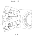
- each receiving location has a turntable 12 which is driven by a cam-controlled rotary drive 13, which is shown in detail in FIG.
- the turntable 12 is adapted on its top to the shape of the bottom of the bottle 14, so that the bottle 14 is centered in this way. Presses against the head of the bottle 14 cam-controlled centering clamping head 15.
- the rotary drive consists of a stationary, flat curve 13a, in which a crank 13b mounted in the rotary table is guided with rollers 13c as an engagement member.
- the crank 13b drives with a pinion 13d a shaft 13f of a carrier 13g of the turntable 12 provided with a toothing 13e.
- a spring-loaded pawl 16 is assigned to each receiving location on the side of the bottle 14 facing the center of the rotary table 5, which pawl escapes between the rotary plate 12 and the clamping head 15 when the bottle 14 passed from the inlet star 4 into the receiving location, if the latch 15 is not accidental can snap into a notch 17 on the circumference of the bottle 14. If the pawl 16 snaps into the notch 17 by chance, the bottle 14 is not rotated when the torque acting on it by the driven turntable 12, but is held in the aligned rotational position. The driven turntable 12 then slips against the bottom of the bottle 14.
- the bottle 14 can be rotated with an effective torque until the pawl 16 engages in the notch 17.
- the rotary movement exerted on the turntable 12 ensures a 360 ° rotation from the transfer of the bottle to the turntable 5 to the delivery of the bottle to the intermediate star 6.
- the pawl 16 is arranged on the inside of the bottle 14 facing the center of the rotary table 5
- special precautions are taken to keep the bottle 14 in the aligned rotary position on the intermediate star 6 to be handed over without it being handed over too much load on the pawl 16 and the notch 17 and consequently a rotational offset occurs.
- Such precautions are necessary because, when the center paths of the bottle 14 in the rotary table 5 and in the intermediate star 6 are synchronized, the path speeds of the notch 17 in the rotary table 5 are different than in the intermediate star 6, which is smaller in diameter.
- a correction rotation K is therefore provided so that the bottle 14 with its notch 17 is disengaged from the pawl 16 before the transfer.
- the correction rotation K thus achieves a certain advance.
- the pawls 16 are arranged at the ends of a spoke wheel 18 which is clamped in a rotationally fixed manner on the carrier 20 of the turntable 5 by means of a clamping plate 19. By releasing the clamping plate 19, all pawls 16 can therefore be adjusted together to the desired alignment position.
- the embodiment of Figures 6 and 7 differs from that of Figures 2 and 3 in that the pawls 16 are both tangentially and radially adjustable. As in the exemplary embodiment in FIGS. 2 and 3, they are held at the ends of the spokes of a spoke wheel 21, but in this case can be moved by means of an elongated hole guide 22. Via a rod 23, they are held in an oblique slot guide 25, which is provided in a concentric ring 26 arranged on the spoke wheel 21. The ring 26 can be rotated relative to the spoke wheel 21 after loosening a clamping ring 27, so that all the pawls 16 can be adjusted radially with a single adjustment movement. The circumferential adjustment of the spoke wheel 21 is carried out as in the embodiment of Figures 2 and 3 after loosening a clamping plate 28.
- the embodiment of Figure 8 differs from the described embodiments first of all in that the rotary drive 13 has a slip clutch 30, which is integrated in the pinion 13d ', and that a locking member 31, which is not positively but rather non-positively, is provided, which is provided by a control device 32 is controlled.
- the slip clutch 30 can, however, also be used in the other exemplary embodiments.
- the locking member 31 is equipped with a friction lining 31a, which cooperates with the outer edge of the turntable 12.
- the locking member 31 is pressed against the outer edge of the turntable 12 by an actuator 33.
- the control device 32 activates the actuator 33 as a function of a mark 35 determined on the container 14 by means of a sensor 34.
- a reverse rotation can also be used advantageously in this example.
- a backward rotation can be carried out at a very low angular speed, which allows the blocking in the desired alignment position make precise.
Landscapes
- Engineering & Computer Science (AREA)
- Mechanical Engineering (AREA)
- Labeling Devices (AREA)
- Specific Conveyance Elements (AREA)
Applications Claiming Priority (4)
| Application Number | Priority Date | Filing Date | Title |
|---|---|---|---|
| DE4037382 | 1990-11-23 | ||
| DE4037382 | 1990-11-23 | ||
| DE4120887A DE4120887A1 (de) | 1990-11-23 | 1991-06-25 | Etikettiermaschine fuer behaelter, insbesondere flaschen, mit einer ausrichtvorrichtung fuer die drehstellung |
| DE4120887 | 1991-06-25 |
Publications (2)
| Publication Number | Publication Date |
|---|---|
| EP0487020A1 true EP0487020A1 (fr) | 1992-05-27 |
| EP0487020B1 EP0487020B1 (fr) | 1994-03-09 |
Family
ID=25898729
Family Applications (1)
| Application Number | Title | Priority Date | Filing Date |
|---|---|---|---|
| EP91119705A Expired - Lifetime EP0487020B1 (fr) | 1990-11-23 | 1991-11-19 | Dispositif pour l'orientation en rotation de bouteilles |
Country Status (3)
| Country | Link |
|---|---|
| EP (1) | EP0487020B1 (fr) |
| DE (2) | DE4120887A1 (fr) |
| ES (1) | ES2050495T3 (fr) |
Cited By (7)
| Publication number | Priority date | Publication date | Assignee | Title |
|---|---|---|---|---|
| WO2007025602A1 (fr) * | 2005-08-30 | 2007-03-08 | Krones Ag | Dispositif et procede pour compenser la hauteur dans des machines de traitement de recipients |
| DE102006043106A1 (de) * | 2006-09-14 | 2008-03-27 | Khs Ag | Vorrichtung zur Steuerung der Drehbewegung von Gefäßen |
| ITTO20090830A1 (it) * | 2009-10-28 | 2011-04-29 | Gai S P A | Macchina per l'etichettatura di bottiglie per liquidi alimentari munita di sistema per la ricerca di una tacca di riferimento sul fondo delle bottiglie |
| CN104401559A (zh) * | 2014-11-13 | 2015-03-11 | 杭州灏元自动化设备有限公司 | 全自动贴标机 |
| CN112141467A (zh) * | 2020-10-27 | 2020-12-29 | 安徽海思达机器人有限公司 | 酒瓶自动贴金属片标签的装置 |
| CN113879647A (zh) * | 2021-10-15 | 2022-01-04 | 杭州电子科技大学 | 一种传感器贴标设备 |
| CN120171893A (zh) * | 2025-04-02 | 2025-06-20 | 江苏新美星包装机械股份有限公司 | 一种装盖贴标一体机 |
Families Citing this family (4)
| Publication number | Priority date | Publication date | Assignee | Title |
|---|---|---|---|---|
| DE19927668B4 (de) * | 1999-06-17 | 2004-03-18 | Krones Ag | Verfahren und Vorrichtung zum Herstellen eines ausrichtbaren Behälters |
| DE10145455A1 (de) | 2001-09-14 | 2003-04-24 | Krones Ag | Maschine zum Ausstatten von Arikeln |
| DE20115480U1 (de) | 2001-09-19 | 2002-05-16 | Heuft Systemtechnik Gmbh, 56659 Burgbrohl | Vorrichtung zum Anbringen von Etiketten an Behältern |
| DE102021127195A1 (de) | 2021-10-20 | 2023-04-20 | Krones Aktiengesellschaft | Verschließen von Behältern mit Behälterverschlüssen |
Citations (4)
| Publication number | Priority date | Publication date | Assignee | Title |
|---|---|---|---|---|
| DE2916822A1 (de) * | 1979-04-26 | 1980-11-06 | Kronseder Hermann | Vorrichtung zum ausrichten von mit nocken, vertiefungen o.dgl. versehenen aufrechtstehenden flaschen in etikettiermaschinen |
| DE3308489A1 (de) * | 1983-03-10 | 1984-09-13 | Krones Ag Hermann Kronseder Maschinenfabrik, 8402 Neutraubling | Zentriervorrichtung fuer aufrecht stehende gefaesse, insbesondere in etikettiermaschinen |
| DE3408834A1 (de) * | 1983-03-12 | 1984-12-20 | Jagenberg AG, 4000 Düsseldorf | Etikettiermaschine fuer gegenstaende, wie flaschen, die im drehtisch ausgerichtet werden |
| DE3347826A1 (de) * | 1983-01-03 | 1985-03-07 | Jagenberg AG, 4000 Düsseldorf | Etikettiermaschine fuer rotationssymmetrische gegenstaende, wie flaschen |
Family Cites Families (5)
| Publication number | Priority date | Publication date | Assignee | Title |
|---|---|---|---|---|
| GB927691A (en) * | 1959-02-23 | 1963-06-06 | Rose Brothers Ltd | Improvements in wrapping machines |
| DE7523323U (de) * | 1975-07-19 | 1975-11-20 | Bekum Maschinenfabriken Gmbh | Drehvorrichtung zur ausrichtung von behaeltern |
| DE2607404C3 (de) * | 1976-02-24 | 1980-02-07 | Kronseder, Hermann, 8404 Woerth | Verfahren und Vorrichtung zum Ausrichten von Gefäßen, insbesondere vor dem Etikettieren |
| DE2903470C2 (de) * | 1979-01-30 | 1989-04-06 | Otto Sick Kg, 7830 Emmendingen | Einrichtung zur Winkelausrichtung von Gefäßen |
| DE3923670A1 (de) * | 1988-07-19 | 1990-01-25 | Rainer Buchholz | Flaschenbehandlungsmaschine fuer buegelverschlussflaschen, insbesondere fuer schliessmaschine in kombination mit etikettiermaschine |
-
1991
- 1991-06-25 DE DE4120887A patent/DE4120887A1/de not_active Withdrawn
- 1991-11-19 DE DE91119705T patent/DE59101161D1/de not_active Expired - Fee Related
- 1991-11-19 ES ES91119705T patent/ES2050495T3/es not_active Expired - Lifetime
- 1991-11-19 EP EP91119705A patent/EP0487020B1/fr not_active Expired - Lifetime
Patent Citations (4)
| Publication number | Priority date | Publication date | Assignee | Title |
|---|---|---|---|---|
| DE2916822A1 (de) * | 1979-04-26 | 1980-11-06 | Kronseder Hermann | Vorrichtung zum ausrichten von mit nocken, vertiefungen o.dgl. versehenen aufrechtstehenden flaschen in etikettiermaschinen |
| DE3347826A1 (de) * | 1983-01-03 | 1985-03-07 | Jagenberg AG, 4000 Düsseldorf | Etikettiermaschine fuer rotationssymmetrische gegenstaende, wie flaschen |
| DE3308489A1 (de) * | 1983-03-10 | 1984-09-13 | Krones Ag Hermann Kronseder Maschinenfabrik, 8402 Neutraubling | Zentriervorrichtung fuer aufrecht stehende gefaesse, insbesondere in etikettiermaschinen |
| DE3408834A1 (de) * | 1983-03-12 | 1984-12-20 | Jagenberg AG, 4000 Düsseldorf | Etikettiermaschine fuer gegenstaende, wie flaschen, die im drehtisch ausgerichtet werden |
Cited By (9)
| Publication number | Priority date | Publication date | Assignee | Title |
|---|---|---|---|---|
| WO2007025602A1 (fr) * | 2005-08-30 | 2007-03-08 | Krones Ag | Dispositif et procede pour compenser la hauteur dans des machines de traitement de recipients |
| US7921980B2 (en) | 2005-08-30 | 2011-04-12 | Krones Ag | Device and method for vertical adjustment in container processing machines |
| DE102006043106A1 (de) * | 2006-09-14 | 2008-03-27 | Khs Ag | Vorrichtung zur Steuerung der Drehbewegung von Gefäßen |
| ITTO20090830A1 (it) * | 2009-10-28 | 2011-04-29 | Gai S P A | Macchina per l'etichettatura di bottiglie per liquidi alimentari munita di sistema per la ricerca di una tacca di riferimento sul fondo delle bottiglie |
| CN104401559A (zh) * | 2014-11-13 | 2015-03-11 | 杭州灏元自动化设备有限公司 | 全自动贴标机 |
| CN112141467A (zh) * | 2020-10-27 | 2020-12-29 | 安徽海思达机器人有限公司 | 酒瓶自动贴金属片标签的装置 |
| CN113879647A (zh) * | 2021-10-15 | 2022-01-04 | 杭州电子科技大学 | 一种传感器贴标设备 |
| CN113879647B (zh) * | 2021-10-15 | 2022-11-01 | 杭州电子科技大学 | 一种传感器贴标设备 |
| CN120171893A (zh) * | 2025-04-02 | 2025-06-20 | 江苏新美星包装机械股份有限公司 | 一种装盖贴标一体机 |
Also Published As
| Publication number | Publication date |
|---|---|
| ES2050495T3 (es) | 1994-05-16 |
| DE59101161D1 (de) | 1994-04-14 |
| DE4120887A1 (de) | 1992-06-11 |
| EP0487020B1 (fr) | 1994-03-09 |
Similar Documents
| Publication | Publication Date | Title |
|---|---|---|
| DE3308934C1 (de) | Etikettiermaschine | |
| DE60114777T2 (de) | Vorrichtung zur übergabe von behältern mit einem führungsrad variabler geometrie | |
| DE3022343C2 (de) | Vorrichtung zum Ausrichten von Flaschen o.dgl., insbesondere in Etikettiermaschinen | |
| EP0326705B1 (fr) | Dispositif de modification des distances entre des objets se déplaçant l'un après l'autre | |
| EP0487020B1 (fr) | Dispositif pour l'orientation en rotation de bouteilles | |
| EP1427639A2 (fr) | Dispositif pour apposer des etiquettes sur des recipients | |
| EP1205388A1 (fr) | Dispositif pour contrôler le mouvement rotatif de conteneurs | |
| DE9006376U1 (de) | Vorrichtung zum Zentrieren und Ausrichten von Gefäßen | |
| DE3219906A1 (de) | Etikettiermaschine | |
| EP0422425B1 (fr) | Poste de lissage pour presser des feuilles d'habillage posées sur la tête et sur le goulot de bouteilles | |
| WO2010063347A1 (fr) | Système de chargement de récipients et machine de traitement présentant un tel système de chargement | |
| DE4119407C2 (de) | Behandlungsmaschine für Behälter, insbesondere Flaschen | |
| DE3922934C2 (fr) | ||
| DE69402772T2 (de) | Vorrichtung zum Zentrieren und Anbringen von Siegelkapseln auf Flaschen | |
| DE19821253B4 (de) | Etikettiermaschine | |
| DE19911074A1 (de) | Vorrichtung zum Etikettieren von Flaschen mit einem Etikettieraggregat | |
| DE3244485C2 (de) | Transportvorrichtung in Form eines Drehtisches in einer Etikettiermaschine insbesondere für Hebel- oder Bügelverschlußflaschen | |
| DE3131102C1 (de) | Foerderschnecke fuer Gegenstaende wie Formflaschen etc. | |
| DE2435582C3 (de) | Entnahmeelement für Etiketten in einer Etikettiermaschine | |
| DE3025178A1 (de) | Etikettiermaschine fuer waehrend ihrer verdrehung formschluessig gehaltene behaelter | |
| DE2916822A1 (de) | Vorrichtung zum ausrichten von mit nocken, vertiefungen o.dgl. versehenen aufrechtstehenden flaschen in etikettiermaschinen | |
| DE2701808B2 (de) | Etikettierstation einer Etikettiermaschine für Gegenstände, wie Flaschen | |
| DE19851733C2 (de) | Transportvorrichtung sowie Etikettiermaschine mit einer solchen Transportvorrichtung | |
| DE3435681C2 (fr) | ||
| DE2455189A1 (de) | Befoerderungsvorrichtung fuer rotationskoerper |
Legal Events
| Date | Code | Title | Description |
|---|---|---|---|
| PUAI | Public reference made under article 153(3) epc to a published international application that has entered the european phase |
Free format text: ORIGINAL CODE: 0009012 |
|
| AK | Designated contracting states |
Kind code of ref document: A1 Designated state(s): DE ES FR GB IT |
|
| 17P | Request for examination filed |
Effective date: 19920907 |
|
| 17Q | First examination report despatched |
Effective date: 19930330 |
|
| ITF | It: translation for a ep patent filed | ||
| GRAA | (expected) grant |
Free format text: ORIGINAL CODE: 0009210 |
|
| AK | Designated contracting states |
Kind code of ref document: B1 Designated state(s): DE ES FR GB IT |
|
| GBT | Gb: translation of ep patent filed (gb section 77(6)(a)/1977) |
Effective date: 19940314 |
|
| REF | Corresponds to: |
Ref document number: 59101161 Country of ref document: DE Date of ref document: 19940414 |
|
| REG | Reference to a national code |
Ref country code: ES Ref legal event code: FG2A Ref document number: 2050495 Country of ref document: ES Kind code of ref document: T3 |
|
| ET | Fr: translation filed | ||
| PGFP | Annual fee paid to national office [announced via postgrant information from national office to epo] |
Ref country code: DE Payment date: 19940829 Year of fee payment: 4 |
|
| PGFP | Annual fee paid to national office [announced via postgrant information from national office to epo] |
Ref country code: FR Payment date: 19940915 Year of fee payment: 4 |
|
| PGFP | Annual fee paid to national office [announced via postgrant information from national office to epo] |
Ref country code: ES Payment date: 19940919 Year of fee payment: 4 |
|
| PLBE | No opposition filed within time limit |
Free format text: ORIGINAL CODE: 0009261 |
|
| STAA | Information on the status of an ep patent application or granted ep patent |
Free format text: STATUS: NO OPPOSITION FILED WITHIN TIME LIMIT |
|
| 26N | No opposition filed | ||
| PG25 | Lapsed in a contracting state [announced via postgrant information from national office to epo] |
Ref country code: GB Effective date: 19951119 |
|
| PG25 | Lapsed in a contracting state [announced via postgrant information from national office to epo] |
Ref country code: ES Free format text: LAPSE BECAUSE OF NON-PAYMENT OF DUE FEES Effective date: 19951120 |
|
| GBPC | Gb: european patent ceased through non-payment of renewal fee |
Effective date: 19951119 |
|
| PG25 | Lapsed in a contracting state [announced via postgrant information from national office to epo] |
Ref country code: FR Effective date: 19960731 |
|
| REG | Reference to a national code |
Ref country code: FR Ref legal event code: ST |
|
| PG25 | Lapsed in a contracting state [announced via postgrant information from national office to epo] |
Ref country code: DE Effective date: 19961001 |
|
| REG | Reference to a national code |
Ref country code: ES Ref legal event code: FD2A Effective date: 19961213 |
|
| PG25 | Lapsed in a contracting state [announced via postgrant information from national office to epo] |
Ref country code: IT Free format text: LAPSE BECAUSE OF NON-PAYMENT OF DUE FEES Effective date: 20051119 |