EP0487054A2 - Connecteur optique comprenant un adaptateur avec dispositif pour connecter/déconnecter un contact optique - Google Patents
Connecteur optique comprenant un adaptateur avec dispositif pour connecter/déconnecter un contact optique Download PDFInfo
- Publication number
- EP0487054A2 EP0487054A2 EP91119765A EP91119765A EP0487054A2 EP 0487054 A2 EP0487054 A2 EP 0487054A2 EP 91119765 A EP91119765 A EP 91119765A EP 91119765 A EP91119765 A EP 91119765A EP 0487054 A2 EP0487054 A2 EP 0487054A2
- Authority
- EP
- European Patent Office
- Prior art keywords
- optical
- contact
- circuit board
- connection adapter
- holding member
- Prior art date
- Legal status (The legal status is an assumption and is not a legal conclusion. Google has not performed a legal analysis and makes no representation as to the accuracy of the status listed.)
- Granted
Links
Images







Classifications
-
- G—PHYSICS
- G02—OPTICS
- G02B—OPTICAL ELEMENTS, SYSTEMS OR APPARATUS
- G02B6/00—Light guides; Structural details of arrangements comprising light guides and other optical elements, e.g. couplings
- G02B6/24—Coupling light guides
- G02B6/36—Mechanical coupling means
- G02B6/38—Mechanical coupling means having fibre to fibre mating means
- G02B6/3807—Dismountable connectors, i.e. comprising plugs
- G02B6/3897—Connectors fixed to housings, casing, frames or circuit boards
-
- G—PHYSICS
- G02—OPTICS
- G02B—OPTICAL ELEMENTS, SYSTEMS OR APPARATUS
- G02B6/00—Light guides; Structural details of arrangements comprising light guides and other optical elements, e.g. couplings
- G02B6/24—Coupling light guides
- G02B6/36—Mechanical coupling means
- G02B6/38—Mechanical coupling means having fibre to fibre mating means
- G02B6/3807—Dismountable connectors, i.e. comprising plugs
- G02B6/381—Dismountable connectors, i.e. comprising plugs of the ferrule type, e.g. fibre ends embedded in ferrules, connecting a pair of fibres
- G02B6/3823—Dismountable connectors, i.e. comprising plugs of the ferrule type, e.g. fibre ends embedded in ferrules, connecting a pair of fibres containing surplus lengths, internal fibre loops
-
- G—PHYSICS
- G02—OPTICS
- G02B—OPTICAL ELEMENTS, SYSTEMS OR APPARATUS
- G02B6/00—Light guides; Structural details of arrangements comprising light guides and other optical elements, e.g. couplings
- G02B6/24—Coupling light guides
- G02B6/36—Mechanical coupling means
- G02B6/38—Mechanical coupling means having fibre to fibre mating means
- G02B6/3807—Dismountable connectors, i.e. comprising plugs
- G02B6/381—Dismountable connectors, i.e. comprising plugs of the ferrule type, e.g. fibre ends embedded in ferrules, connecting a pair of fibres
- G02B6/3825—Dismountable connectors, i.e. comprising plugs of the ferrule type, e.g. fibre ends embedded in ferrules, connecting a pair of fibres with an intermediate part, e.g. adapter, receptacle, linking two plugs
-
- G—PHYSICS
- G02—OPTICS
- G02B—OPTICAL ELEMENTS, SYSTEMS OR APPARATUS
- G02B6/00—Light guides; Structural details of arrangements comprising light guides and other optical elements, e.g. couplings
- G02B6/24—Coupling light guides
- G02B6/36—Mechanical coupling means
- G02B6/38—Mechanical coupling means having fibre to fibre mating means
- G02B6/3807—Dismountable connectors, i.e. comprising plugs
- G02B6/3869—Mounting ferrules to connector body, i.e. plugs
-
- G—PHYSICS
- G02—OPTICS
- G02B—OPTICAL ELEMENTS, SYSTEMS OR APPARATUS
- G02B6/00—Light guides; Structural details of arrangements comprising light guides and other optical elements, e.g. couplings
- G02B6/24—Coupling light guides
- G02B6/36—Mechanical coupling means
- G02B6/38—Mechanical coupling means having fibre to fibre mating means
- G02B6/3807—Dismountable connectors, i.e. comprising plugs
- G02B6/3873—Connectors using guide surfaces for aligning ferrule ends, e.g. tubes, sleeves, V-grooves, rods, pins, balls
- G02B6/3874—Connectors using guide surfaces for aligning ferrule ends, e.g. tubes, sleeves, V-grooves, rods, pins, balls using tubes, sleeves to align ferrules
- G02B6/3875—Floatingly supported sleeves
-
- G—PHYSICS
- G02—OPTICS
- G02B—OPTICAL ELEMENTS, SYSTEMS OR APPARATUS
- G02B6/00—Light guides; Structural details of arrangements comprising light guides and other optical elements, e.g. couplings
- G02B6/24—Coupling light guides
- G02B6/36—Mechanical coupling means
- G02B6/38—Mechanical coupling means having fibre to fibre mating means
- G02B6/3807—Dismountable connectors, i.e. comprising plugs
- G02B6/3873—Connectors using guide surfaces for aligning ferrule ends, e.g. tubes, sleeves, V-grooves, rods, pins, balls
- G02B6/3874—Connectors using guide surfaces for aligning ferrule ends, e.g. tubes, sleeves, V-grooves, rods, pins, balls using tubes, sleeves to align ferrules
- G02B6/3878—Connectors using guide surfaces for aligning ferrule ends, e.g. tubes, sleeves, V-grooves, rods, pins, balls using tubes, sleeves to align ferrules comprising a plurality of ferrules, branching and break-out means
-
- G—PHYSICS
- G02—OPTICS
- G02B—OPTICAL ELEMENTS, SYSTEMS OR APPARATUS
- G02B6/00—Light guides; Structural details of arrangements comprising light guides and other optical elements, e.g. couplings
- G02B6/24—Coupling light guides
- G02B6/36—Mechanical coupling means
- G02B6/38—Mechanical coupling means having fibre to fibre mating means
- G02B6/3807—Dismountable connectors, i.e. comprising plugs
- G02B6/381—Dismountable connectors, i.e. comprising plugs of the ferrule type, e.g. fibre ends embedded in ferrules, connecting a pair of fibres
- G02B6/3817—Dismountable connectors, i.e. comprising plugs of the ferrule type, e.g. fibre ends embedded in ferrules, connecting a pair of fibres containing optical and electrical conductors
Definitions
- This invention relates to an optical connector for use in a communication apparatus or the like and, in particular, to an optical connector comprising an optical connection adapter with means for connection/disconnection of an optical contact.
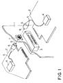
- a recent communication apparatus includes a plurality of circuit boards. For interconnection between those circuit boards, use is made of an optical connector in addition to an electrical connector, as shown in Fig. 1.
- a printed wiring board 1 has the opposite surfaces each of which is for mounting a circuit board 2 to be arranged perpendicular to the printed wiring board 1.
- the printed wiring board 1 is provided with an electrical connector 3 so as to interconnect the circuit boards 2 on the opposite surfaces.
- the circuit boards 2 are also connected through an optical connector.
- the optical connector comprises optical plugs 6 and an adapter 7 attached to the printed wiring board 1.
- An optical cable 5 is connected to each optical plug 6.
- the optical cable 5 is also connected to a converter 4 placed on each circuit board 2.
- the adapter 7 serves to facilitate interconnection between the optical plugs 6.
- the optical connector illustrated in Fig. 1 is a so-called single core connector having one optical contact 8. Therefore, a relatively wide space is required for connection of one optical connector. Consequently, such a conventional optical connector is not suitable for connection of a plurality of connectors. In addition, the conventional optical connector is disadvantageous in that it takes a lot of labor for mounting operation.
- an optical connector unit which comprises an optical plug comprising an optical contact connected to an optical cable, a contact holding member for holding the optical contact, and a housing for supporting the contact holding member to be movable along an optical axis of the optical contact, and an optical connection adapter to be attached to a circuit board for holding the optical plug.
- the optical connection adapter includes a main housing to be attached to the circuit board and optical contact driving means movable in the main housing and engaged with the contact holding member for driving the contact holding member along the optical axis.
- the optical contact driving means is a slider having a groove engaged with the contact holding member so as to drive the contact holding member along the optical axis.
- the main housing is provided at a portion adjacent to the circuit board with a sleeve for removably receiving the optical contact.
- an optical connection adapter which comprises a pipe to be attached to a through hole of a circuit board so as to extend from one surface to other surface of the circuit board, an optical fiber inserted into the pipe, a first and a second optical contact connected to opposite ends of the optical fiber, respectively, and a first and a second contact holding member for holding the first and the second optical contacts, respectively, and coupled to the pipe to be movable along a cylindrical axis of the pipe.
- the optical connection adapter is mated with a first and a second optical socket to form an optical connector.
- the first optical socket comprises a first housing provided with a first insertion hole for removably receiving the first optical contact of the optical connection adapter, and a third optical contact inserted into the first insertion hole and fixed to the first housing so that an optical axis of the third optical contact coincides with that of the first optical contact.
- the second optical socket comprises a second housing provided with a second insertion hole for removably receiving the second optical contact of the optical connection adapter, and a fourth optical contact inserted into the second insertion hole and fixed to the second housing so that an optical axis of the fourth optical contact coincides with that of the second optical contact.
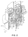
- Fig. 2 is a perspective sectional view illustrating two optical connectors according to a first embodiment of this invention when applied to a printed wiring board. Description will be made as regards one optical connector alone for the purpose of simplification.
- a circuit board of a particular type or a printed wiring board 1 has the opposite surfaces each mounting another circuit board 2 arranged perpendicular to the printed wiring board 1. Positional relationship between those circuit boards 2 on the opposite surfaces will become clear as the description proceeds.
- the printed wiring board 1 is provided with a through hole 11 in correspondence with the circuit boards 2. Practically, a plurality of the through holes 11 are formed along the circuit boards to be aligned in a straight line, although only one hole is observed in the figure. A cylindrical alignment sleeve 12 is inserted in the through hole 11 to penetrate therethrough. The alignment sleeve 12 has a length larger than the thickness of the printed wiring board 1.
- a main housing 13 of an insulating material is secured to each of the opposite surfaces of the printed wiring board 1.
- the main housing 13 is provided with an insertion hole 15 which is formed at a portion adjacent to the printed wiring board 1, namely, a bottom portion 14 and which is for receiving an end portion of the alignment sleeve 12.
- the insertion hole 15 has a narrowed portion in the vicinity of the internal surface of the main housing 13. The diameter of the narrowed portion is smaller than the outer diameter of the alignment sleeve 12. Accordingly, the alignment sleeve 12 is prevented by the bottom portion 14 of the main housing 13 from being dislocated along the cylindrical axis.
- the bottom portion 14 serves as a sleeve holding member for holding the alignment sleeve 12.
- the main housing 13 defines a housing groove 17 extending along a first direction 16 parallel to the printed wiring board 1 and the circuit board 2.
- two sliders 18 extend along the both side walls, respectively. As shown in Fig. 3, the two sliders 18 are integrally coupled to each other.
- the sliders 18 are slidable along the first direction 16.
- Each slider 18 has a cam groove 19 extending substantially along the first direction 16.
- the cam groove 19 has a slant portion 19a at its center portion, as shown in Fig. 3.
- the slant portion 19a is slanted with respect to the first direction 16.
- a plug housing 21 is located between the two sliders 18.
- the plug housing 21 is provided with a bore 22.
- the plug housing 21 is fixed to the circuit board 2 through a screw (not shown) penetrating through the bore 22.
- a plurality of the plug housings 21 are arranged along the housing groove 17, although only one plug housing is shown in the figure.
- the plug housing 21 encloses a contact holding member 23.
- the contact holding member 23 enclosed in the plug housing 21 is slidable along a second direction 24 perpendicular to the printed wiring board 1.
- the contact holding member 23 holds an optical contact 25.
- the optical contact 25 held by the contact holding member 23 has the optical axis coincident with the cylindrical axis of the alignment sleeve 12.
- An optical fiber 26 is connected to the optical contact 25.
- the optical fiber 26 is also connected to a converter (not shown) on the circuit board 2 so as to leave the slack.
- a tip 27 of the optical contact 25 has an outer diameter slightly smaller than the internal diameter of the alignment sleeve 12.
- the contact holding member 23 has protrusions 28 slidably inserted in the cam grooves 19 of the sliders 18. When the sliders 18 are moved along the first direction 16, the contact holding member 23 is driven along the second direction 24 in accordance with the configuration of the cam groove 19.
- An optical plug is formed by a combination of the optical contact 25, the contact holding member 23, and the plug housing 21 described above. Although not clearly shown in the figure, a plurality of the optical plugs are arranged in a straight line on each circuit board 2.
- an optical connection adapter is formed by a combination of the main housing 13, a plurality of the alignment sleeves 12 arranged in a straight line in the main housing 13, the sliders 18 arranged in the main housing.
- An optical connector unit is formed by a combination of a plurality of the optical plugs arranged in a straight line on the circuit board 2 and the optical connection adapter.
- a first optical connector unit is located on the upper surface of the printed wiring board 1 while a second optical connector unit is located on the lower surface of the printed wiring board 1, as shown in Fig. 2.
- One optical connector is formed by a combination of the first optical connector unit and the second optical connector unit corresponding to the first optical connector unit.
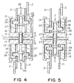
- Fig. 4 shows the optical connector according to the first embodiment in a disconnected state.
- the sliders 18 are moved along the first direction 16 in the disconnected state, the cam grooves 19 and the protrusions 28 are engaged with each other.
- the contact holding member 23 is moved towards the bottom portion 14 of the main housing 13 by the slant portions 19a of the cam grooves 19.
- the tip 27 of the optical contact 25 is smoothly inserted into the alignment sleeve 12.
- the above-mentioned operation is carried out on each of the opposite surfaces of the printed wiring board 27 to make the tip 27 of the optical contact 25 be brought into contact with that of the mating optical contact 25, as shown in Fig. 5.
- the optical connector is put into a connection state.
- Fig. 6 is a perspective view illustrating the entire configuration of the first embodiment shown in Fig. 2.
- a plurality of the first optical connector units 31 are arranged on the upper surface of the printed wiring board 1 in a same direction.
- a plurality of the second optical connector units 32 are arranged on the lower surface of the printed wiring board 1 in a same direction.
- the longitudinal direction of each of the second optical connector units 32 is parallel to the longitudinal direction of each of the first optical connector units 31.
- Each of the second optical connector units 32 is opposite to each of the first optical connector units 31 with the printed wiring board 1 being interposed therebetween.
- the circuit board 2 is mounted on each of the first and the second optical connector units 31 and 32.
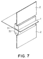
- Fig. 7 shows a perspective view illustrating the entire configuration of a second embodiment.
- An optical connector according to the second embodiment comprises a first and a second optical connector unit 31 and 32 similar to those of the first embodiment illustrated in Figs. 2 through 6. However, the number of the first and the second optical connector units 31 and 32 is different from that of the first embodiment.
- a single first optical connector unit 31 is arranged on the upper surface of the printed wiring board 1.
- a single second optical connector unit 32 is arranged on the lower surface of the printed wiring board 1.
- the longitudinal direction of the second optical connector unit 32 is parallel to the longitudinal direction of the first optical connector unit 31.
- the second optical connector unit 32 is opposite to the first optical connector unit 31 with the printed wiring board 1 interposed therebetween.
- the circuit board 2 is mounted on each of the first and the second optical connector units 31 and 32.
- Fig. 8 is a perspective view illustrating the entire configuration of a third embodiment.
- An optical connector according to the third embodiment comprises a first and a second optical connector unit 31 and 32 similar to those of the first embodiment illustrated in Figs. 2 through 6. However, the arrangement of the first and the second optical connector units 31 and 32 is different from that of the first embodiment.
- a plurality of the first optical connector units 31 are arranged on the upper surface of the printed wiring board 1 in a same direction.
- a plurality of the second optical connector units 32 are arranged on the lower surface of the printed wiring board 1 in a same direction.
- the longitudinal direction of the second optical connector unit 32 is perpendicular to the longitudinal direction of the first optical connector unit 31.
- Each of the second optical connector units 32 is partially opposite to each of the first optical connector units 31 with the printed wiring board 1 being interposed therebetween.
- the circuit board 2 is mounted on each of the first and the second optical connector units 31 and 32.
- Fig. 9 is a perspective view illustrating the entire configuration of a fourth embodiment.
- An optical connector according to the fourth embodiment comprises a first and a second optical connector unit 31 and 32 similar to those of the third embodiment shown in Fig. 8. However, the number of the first and the second optical connector units 31 and 32 is different from that of the third embodiment.
- a single first optical connector unit 31 is arranged on the upper surface of the printed wiring board 1.
- a single second optical connector unit 32 is arranged on the lower surface of the printed circuit board 1.
- the longitudinal direction of the second optical connector unit 32 is perpendicular to the longitudinal direction of the first optical connector unit 31.
- One end of the second optical connector unit 32 is opposite to one end of the first optical connector unit 31 with the printed circuit board 1 being interposed therebetween.
- the circuit board 2 is mounted on each of the first and the second optical connector units 31 and 32.
- the optical connector unit comprises a plurality of the optical plugs.
- the optical connector unit may comprise only one optical plug.
- the optical connection adapter includes the main housing and the sliders. However, they are not necessarily required. After all, it is sufficient that the optical connection adapter is attachable to the circuit board and can hold the optical plug.
- the optical plug is held to the main housing through the sliders. Instead, the main housing may directly hold the optical plug to be movable along its optical axis.
- the sliders having the grooves are used as optical contact driving means for driving the contact holding member along the optical axis.
- the optical contact driving means may be implemented by other suitable means instead of the sliders.
- the optical connector unit comprises the alignment sleeve. However, the alignment sleeve is not necessarily required.
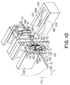
- Fig. 10 is a perspective sectional view illustrating two optical connectors according to a fifth embodiment of this invention when applied to a printed wiring board. Description will be made as regards one optical connector alone for the purpose of simplification.
- a circuit board of a particular type or a printed wiring board 51 is provided with a through hole 61.
- a pipe 62 of a cylindrical shape having a rectangular section is inserted into the through hole 61 to penetrate therethrough.
- the pipe 62 has a flange portion 62a.
- the flange portion 62a has a thickness similar to the thickness of the printed wiring board 51.
- a plurality of the pipes 62 are placed in each of first and second main housings 63 and 63, which will later be described, to be alined in a straight line along the longitudinal direction of the housing.
- only one pipe 62 is illustrated in the figure.
- the first and the second main housings 63 and 63 of an insulating material are secured to the opposite surfaces of the printed wiring boards 51, respectively.
- Each main housing 63 is provided with an insertion hole 65 which is formed at a portion adjacent to the printed wiring board 51, namely, a bottom portion 64 and which is for receiving the pipe 62.
- the flange portion 62a of the pipe 62 is interposed between the first and the second main housings 63 and 63.
- the pipe 62 is fixed to the printed wiring board 51.
- Each of the first and the second main housings 63 and 63 defines a housing groove 67.
- the housing groove 67 extends along a first direction 66 parallel to the printed wiring board 51 and a circuit board 52 (see Figs. 17 and 18).
- two sliders 68 extend along the both side walls, respectively.
- the two sliders 68 are integrally coupled to each other.
- the sliders 68 are slidable along the first direction 66.
- Each slider 68 has a cam groove 69 extending substantially along the first direction 66.
- the cam groove 69 has a slant portion 69a at its center portion.
- the slant portion 69a is slanted with respect to the first direction 66.
- first and second contact holding members 71 are inserted in the upper and the lower ends of the pipe 62, respectively.
- the contact holding members 71 inserted into the pipe 62 are slidable along the cylindrical axis, namely, a second direction 72 perpendicular to the printed wiring board 51.
- the first and the second contact holding members 71 and 71 hold first and second optical contacts 73 and 73, respectively.
- Each optical contact 73 held by the contact holding member 71 has the optical axis coincident with the cylindrical axis of the pipe 62.
- the first and the second optical contacts 73 and 73 are connected to each other through an optical fiber 74 having the sufficient slack.
- the contact holding member 71 has a protrusion 75 engaged with the cam groove 69 of the slider 68. As a result, when the sliders 68 are moved along the first direction 66, the contact holding member 71 is driven along the second direction 72 in accordance with the configuration of the cam groove 69. Consequently, the optical contact 73 is driven along the second direction 72 by the contact holding member 71.
- An optical fiber unit is formed by a combination of the first and the second contact holding members 71 and 71, the first and the second optical contacts 73 and 73, and the optical fiber 74.
- the length of the optical fiber unit in the second direction 72 is elongated and contracted with the movement of the sliders 68 along the first direction 66.
- An optical connection adapter is formed by a combination of the above-mentioned optical fiber unit, the pipe 62, the first and the second main housings 63 and 63, and the sliders 68.
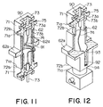
- Fig. 11 is a perspective sectional view of the optical connection adapter in the fifth embodiment shown in Fig. 10 in a most contracted state.
- Fig. 12 is a perspective sectional view of the optical connection adapter in the same embodiment in a most elongated state.
- Fig. 13 is a perspective disassembled view of a main portion of the optical connection adapter in the same embodiment.
- the optical fiber unit comprises the first and the second optical contacts 73 and 73, the optical fiber 74, and the first and the second contact holding members 71 and 71.
- the optical fiber 74 has a spiral shape.
- the first and the second optical contacts 73 and 73 are fixed by a fixing plate 90 in the first and the second contact holding members 71 and 71.
- a fixing plate 90 in the first and the second contact holding members 71 and 71.
- a protrusion 92 formed on the side wall of the contact holding member 71 is brought into contact with a bottom portion 94 of a groove 93 formed in the pipe 62 for receiving the projection 92.
- the optical fiber unit is prevented from being further elongated.
- the optical fiber 74 is made to be slightly slack as compared with the tensive state.
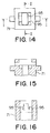
- each optical contact 73 has a flange portion 73a.
- the flange portion 73a has a cut-off portion 73b.
- each contact holding member 71 has an inner wall surface 95 formed to receive the flange portion 73a.
- the inner wall surface 95 is made to engage the flange portion 73a of the optical contact 73.
- the inner wall surface 95 prevents the rotation of the optical contact 73 when the optical fiber unit is elongated and contracted.
- the optical fiber 74 may preliminarily be twisted when the second optical contact 73 is fixed to the second contact holding member 71 after the first optical contact 73 is fixed to the first contact holding member 71. In this state, the second optical contact 73 is fixed to the second contact holding member 71.
- preliminarily twisting the optical fiber 74 as mentioned above, optical fiber 74 is prevented from being substantially twisted when the optical fiber 74 is elongated along the optical axis of the optical contact 73.
- the optical fiber 74 contracted at maximum is preliminarily twisted in an optically allowable extent in a direction opposite to that of the twisting movement occurring when the optical fiber 74 is elongated.
- preliminarily twisting the optical fiber 74 it is possible to effectively disperse the stress produced in the optical fiber 74 when the optical fiber unit is elongated and contracted.
- the optical fiber 74 is not necessarily twisted preliminarily.
- the printed wiring board 51 has the opposite surfaces each mounting the circuit board 52 arranged perpendicularly to the printed wiring board 51. Positional relationship between the circuit boards 52 on the opposite surfaces will become clear as the description proceeds.
- Socket housings 76 of an insulating material are located at the upper and the lower portions of the above-mentioned optical connection adapter, respectively. Each socket housing 76 is fixed to the circuit board 52.
- the first socket housing 76 is provided with a bore 76a.
- An alignment sleeve 77 is inserted into the bore 76a.
- the alignment sleeve 77 serves as a first insertion hole for removably receiving the first optical contact 73.
- One end of a third optical contact 78 is inserted into the alignment sleeve 77 to be fixed.
- the third optical contact 78 fixed to the first socket housing 76 has the optical axis coincident with the optical axis of the first optical contact 73.
- a first optical socket is formed by a combination of the first socket housing 76, the alignment sleeve 77, and the third optical contact 78 mentioned above.
- the second socket housing 76 is provided with the bore 76a.
- the alignment sleeve 77 is inserted into the bore 76a.
- the alignment sleeve 77 serves as a second insertion hole for removably receiving the second optical contact 73.
- One end of a fourth optical contact 78 is inserted into the alignment sleeve 77 to be fixed.
- the fourth optical contact 78 fixed to the second socket housing 76 has the optical axis coincident with the optical axis of the second optical contact 73.
- a second optical socket is formed by a combination of the second socket housing 76, the alignment sleeve 77, and the fourth optical contact 78 mentioned above.
- Each alignment sleeve 77 has an inner diameter slightly larger than the outer diameter of a tip portion 79 of the mating optical contact 78.
- An optical fiber 81 is connected to each of other ends of the third and the fourth optical contact 78.
- An optical connector is formed by a combination of the optical connection adapter and the first and the second optical sockets mentioned above.
- Fig. 17 shows the above-mentioned optical connector in a disconnected state.
- the sliders 68 are moved along the first direction 66 in the disconnected state, the cam groove 69 and the protrusion 75 are engaged with each other.
- the contact holding member 71 is moved by the slant portion 69a of the cam groove 69 in a direction away from the printed wiring board 51.
- the tip 79 of the optical contact 73 is smoothly inserted into the alignment sleeve 77.
- the above-mentioned operation is carried out on each of the opposite surfaces of the printed wiring board 51 to make the tip 79 of the optical contact 73 be brought into contact with that of the mating optical contact 78, as shown in Fig. 18.
- the optical connector is put into a connection state.
- Fig. 19 is a perspective view illustrating the entire configuration of the fifth embodiment shown in Fig. 10.
- a plurality of the first main housings 63 are arranged on the upper surface of the printed wiring board 51 in a same direction.
- a plurality of the second main housings 63 are arranged on the lower surface of the printed wiring board 51 in a same direction.
- the longitudinal direction of each of the second main housings 63 is parallel to the longitudinal direction of each of the first main housings 63.
- Each of the second main housings 63 is opposite to each of the first main housing 63 with the printed wiring board 51 being interposed therebetween.
- a plurality of the optical connectors are applied to the printed wiring board 51.
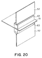
- Fig. 20 is a perspective view illustrating the entire configuration of a sixth embodiment.
- An optical connector according to the sixth embodiment comprises an optical connection adapter, a first and a second optical socket, and a first and a second main housing 63 and 63 similar to those of the fifth embodiment shown in Figs. 10 through 19. However, the number of those components is different from that of the fifth embodiment.
- a single pair of the mating optical connectors are applied to the printed wiring board 51.
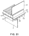
- Fig. 21 is a perspective view illustrating the entire configuration of a seventh embodiment.
- An optical connector according to the seventh embodiment comprises an optical connection adapter, a first and a second optical socket, and a first and a second main housing 63 and 63 similar to those of the fifth embodiment shown in Figs. 10 through 19. However, the arrangement of the first and the second main housings 63 and 63 is different from that of the fifth embodiment.
- a plurality of the first main housings 63 are arranged on the upper surface of the printed wiring board 51 in a same direction.
- a plurality of the second main housings 63 are arranged on the lower surface of the printed wiring board 1 in a same direction.
- the longitudinal direction of the second main housing 63 is perpendicular to the longitudinal direction of the first main housing 63.
- the second main housing 63 is partially opposite to the first main housing 63 with the printed wiring board 51 being interposed therebetween.
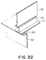
- Fig. 22 is a perspective view illustrating the entire configuration of an eighth embodiment.
- An optical connector according to the eighth embodiment comprises an optical connection adapter, a first and a second optical socket, and a first and a second main housing 63 similar to those of the seventh embodiment shown in Fig. 7. However, the number of the optical connectors is different from that of the seventh embodiment. In the eighth embodiment, a single optical connector is applied to the printed wiring board 51.
- the optical connector comprises a plurality of the optical connection adapters.
- the optical connector may comprise only one optical connection adapter.
- the optical connector comprises a plurality of the optical sockets.
- the optical connector may comprise a pair of optical sockets arranged at both ends of the optical connection adapter.
- the optical connector comprises the main housing and the sliders. However, they are not necessarily required.
- the optical socket is held through the sliders to the main housing. Instead, the main housing may directly hold the optical socket.
- the sliders having the grooves are used as optical contact driving means for driving the contact holding member along the optical axis.
- the optical contact driving means may be implemented by other suitable means instead of the sliders.
- an optical fiber unit according to this invention has a reduced optical loss because the optical fiber is not substantially twisted when it is elongated.
Landscapes
- Physics & Mathematics (AREA)
- General Physics & Mathematics (AREA)
- Optics & Photonics (AREA)
- Mechanical Coupling Of Light Guides (AREA)
Priority Applications (1)
| Application Number | Priority Date | Filing Date | Title |
|---|---|---|---|
| EP95101707A EP0652453B1 (fr) | 1990-11-19 | 1991-11-19 | Connecteur optique comprenant un adapteur avec dispositif pour connecter/déconnecter un contact optique |
Applications Claiming Priority (6)
| Application Number | Priority Date | Filing Date | Title |
|---|---|---|---|
| JP2311324A JP2662605B2 (ja) | 1990-11-19 | 1990-11-19 | 光コネクタ |
| JP311324/90 | 1990-11-19 | ||
| JP1990125232U JP2531571Y2 (ja) | 1990-11-29 | 1990-11-29 | 光接続用アダプタの光ファイバユニット |
| JP125232/90 | 1990-11-29 | ||
| JP3062458A JP2936357B2 (ja) | 1991-03-05 | 1991-03-05 | 光接続用アダプタ及び光コネクタ |
| JP62458/91 | 1991-03-05 |
Related Child Applications (2)
| Application Number | Title | Priority Date | Filing Date |
|---|---|---|---|
| EP95101707A Division EP0652453B1 (fr) | 1990-11-19 | 1991-11-19 | Connecteur optique comprenant un adapteur avec dispositif pour connecter/déconnecter un contact optique |
| EP95101707.8 Division-Into | 1991-11-19 |
Publications (3)
| Publication Number | Publication Date |
|---|---|
| EP0487054A2 true EP0487054A2 (fr) | 1992-05-27 |
| EP0487054A3 EP0487054A3 (en) | 1992-08-26 |
| EP0487054B1 EP0487054B1 (fr) | 1996-02-07 |
Family
ID=27297843
Family Applications (2)
| Application Number | Title | Priority Date | Filing Date |
|---|---|---|---|
| EP95101707A Expired - Lifetime EP0652453B1 (fr) | 1990-11-19 | 1991-11-19 | Connecteur optique comprenant un adapteur avec dispositif pour connecter/déconnecter un contact optique |
| EP91119765A Expired - Lifetime EP0487054B1 (fr) | 1990-11-19 | 1991-11-19 | Connecteur optique comprenant un adaptateur avec dispositif pour connecter/déconnecter un contact optique |
Family Applications Before (1)
| Application Number | Title | Priority Date | Filing Date |
|---|---|---|---|
| EP95101707A Expired - Lifetime EP0652453B1 (fr) | 1990-11-19 | 1991-11-19 | Connecteur optique comprenant un adapteur avec dispositif pour connecter/déconnecter un contact optique |
Country Status (3)
| Country | Link |
|---|---|
| US (1) | US5239606A (fr) |
| EP (2) | EP0652453B1 (fr) |
| DE (2) | DE69131026T2 (fr) |
Cited By (2)
| Publication number | Priority date | Publication date | Assignee | Title |
|---|---|---|---|---|
| WO2000022469A1 (fr) * | 1998-10-13 | 2000-04-20 | Interlemo Holding S.A. | Systeme de connecteur pour contacts males de fibres optiques |
| CN105242358A (zh) * | 2015-11-17 | 2016-01-13 | 精微视达医疗科技(武汉)有限公司 | 一种可以精确定位的光纤连接器 |
Families Citing this family (9)
| Publication number | Priority date | Publication date | Assignee | Title |
|---|---|---|---|---|
| US5325455A (en) * | 1992-10-21 | 1994-06-28 | Minnesota Mining And Manufacturing Company | Fiber optic edge card connector |
| US5631807A (en) * | 1995-01-20 | 1997-05-20 | Minnesota Mining And Manufacturing Company | Electronic circuit structure with aperture suspended component |
| US6863444B2 (en) | 2000-12-26 | 2005-03-08 | Emcore Corporation | Housing and mounting structure |
| US6799902B2 (en) | 2000-12-26 | 2004-10-05 | Emcore Corporation | Optoelectronic mounting structure |
| US6905260B2 (en) | 2000-12-26 | 2005-06-14 | Emcore Corporation | Method and apparatus for coupling optical elements to optoelectronic devices for manufacturing optical transceiver modules |
| US6867377B2 (en) | 2000-12-26 | 2005-03-15 | Emcore Corporation | Apparatus and method of using flexible printed circuit board in optical transceiver device |
| US7021836B2 (en) | 2000-12-26 | 2006-04-04 | Emcore Corporation | Attenuator and conditioner |
| US6863453B2 (en) | 2003-01-28 | 2005-03-08 | Emcore Corporation | Method and apparatus for parallel optical transceiver module assembly |
| US20060093271A1 (en) * | 2004-11-03 | 2006-05-04 | Fenwick David M | Optical connections and methods of forming optical connections |
Family Cites Families (10)
| Publication number | Priority date | Publication date | Assignee | Title |
|---|---|---|---|---|
| US4167303A (en) * | 1977-07-28 | 1979-09-11 | Amp Incorporated | Light transmitting fiber cable connector |
| US4182546A (en) * | 1978-02-21 | 1980-01-08 | Northern Telecom Limited | Multiple connector for optical fibres |
| JPS5788770A (en) * | 1980-11-21 | 1982-06-02 | Hitachi Ltd | Photo semiconductor device |
| JPS5878111A (ja) * | 1981-11-04 | 1983-05-11 | Sumitomo Electric Ind Ltd | 複芯コネクタ |
| US4699454A (en) * | 1984-03-29 | 1987-10-13 | American Telephone And Telegraph Company, At&T Bell Laboratories | Fiber optic connector |
| US4737008A (en) * | 1984-10-01 | 1988-04-12 | Mitsumi Electric Co., Ltd. | Optical transmitting and/or receiving module |
| US4852963A (en) * | 1987-06-30 | 1989-08-01 | American Telephone And Telegraph Company, At&T Bell Laboratories | Optical fiber biconic connector |
| US4828353A (en) * | 1987-07-07 | 1989-05-09 | Japan National Oil Corp. | Submersible optical wet connector |
| US5069524A (en) * | 1988-03-07 | 1991-12-03 | Honda Giken Kogyo Kabushiki Kaisha | Robot hand optical fiber connector coupling assembly |
| US5121454A (en) * | 1989-11-24 | 1992-06-09 | Nippon Telegraph And Telephone Corporation | Optical connector |
-
1991
- 1991-11-18 US US07/793,993 patent/US5239606A/en not_active Expired - Fee Related
- 1991-11-19 EP EP95101707A patent/EP0652453B1/fr not_active Expired - Lifetime
- 1991-11-19 EP EP91119765A patent/EP0487054B1/fr not_active Expired - Lifetime
- 1991-11-19 DE DE69131026T patent/DE69131026T2/de not_active Expired - Fee Related
- 1991-11-19 DE DE69116999T patent/DE69116999T2/de not_active Expired - Fee Related
Cited By (6)
| Publication number | Priority date | Publication date | Assignee | Title |
|---|---|---|---|---|
| WO2000022469A1 (fr) * | 1998-10-13 | 2000-04-20 | Interlemo Holding S.A. | Systeme de connecteur pour contacts males de fibres optiques |
| EP0996009A1 (fr) * | 1998-10-13 | 2000-04-26 | Interlemo Holding S.A. | Système connecteur pour contacts mâles à fibre optique |
| AU760496B2 (en) * | 1998-10-13 | 2003-05-15 | Interlemo Holding S.A. | Connector system for fibre optic male contacts |
| US6688778B1 (en) | 1998-10-13 | 2004-02-10 | Interlemo Holdings S.A. | Connector system for fiber optic male contacts |
| CN105242358A (zh) * | 2015-11-17 | 2016-01-13 | 精微视达医疗科技(武汉)有限公司 | 一种可以精确定位的光纤连接器 |
| CN105242358B (zh) * | 2015-11-17 | 2017-01-25 | 精微视达医疗科技(武汉)有限公司 | 一种可以精确定位的光纤连接器 |
Also Published As
| Publication number | Publication date |
|---|---|
| DE69116999T2 (de) | 1996-08-08 |
| EP0487054B1 (fr) | 1996-02-07 |
| DE69131026D1 (de) | 1999-04-22 |
| EP0652453B1 (fr) | 1999-03-17 |
| DE69131026T2 (de) | 1999-08-12 |
| EP0487054A3 (en) | 1992-08-26 |
| US5239606A (en) | 1993-08-24 |
| EP0652453A2 (fr) | 1995-05-10 |
| EP0652453A3 (fr) | 1995-10-04 |
| DE69116999D1 (de) | 1996-03-21 |
Similar Documents
| Publication | Publication Date | Title |
|---|---|---|
| US6579013B2 (en) | Optical fiber coupler and an optical fiber coupler incorporated within a transceiver module | |
| US4470660A (en) | Blind mating rack and panel fiber optic connector | |
| EP0660144A1 (fr) | Connecteur optique | |
| US4872736A (en) | Connector assembly having a latching mechanism | |
| US4217030A (en) | Fiberoptic-electronic connector assembly | |
| JP3735011B2 (ja) | ハイブリッドコネクタの組み付け方法 | |
| JPH0338709B2 (fr) | ||
| CA2282055A1 (fr) | Dispositif permettant de raccorder un connecteur de fibres optiques rectangulaire a un connecteur cylindrique | |
| JPH07119855B2 (ja) | コネクタ装置 | |
| JPH04215274A (ja) | コネクタ組立体 | |
| EP0652453B1 (fr) | Connecteur optique comprenant un adapteur avec dispositif pour connecter/déconnecter un contact optique | |
| WO2022156222A1 (fr) | Connecteur photoélectrique et adaptateur photoélectrique | |
| CN111919344B (zh) | 包括末端成叉形以接纳互补连接器的接触引脚的扁平中心接触件和配置成引导接触引脚的固体绝缘结构的rf连接器 | |
| US5397241A (en) | High density electrical connector | |
| KR20020006480A (ko) | 광섬유 커넥터용 정렬 시스템 | |
| EP4451027A1 (fr) | Ensemble adaptateur de fibre optique combinable | |
| PL191206B1 (pl) | Urządzenie wtykowe dla światłowodów | |
| RU2210796C2 (ru) | Соединительное устройство для волоконно-оптических штыревых контактов | |
| EP0736787A3 (fr) | Elément d'interconnexion optique | |
| JP2002116351A (ja) | 光ファイバーコネクタとともに用いられるカップリング用アダプタ | |
| US20260036756A1 (en) | Optical-fiber adapter | |
| CN223582196U (zh) | 一种光纤连接器及连接器组件 | |
| JP2004094249A (ja) | 光短絡インサート及び光短絡プラグ | |
| KR100281639B1 (ko) | 플러그 인 어플리케이션을 위한 적층기능을 갖춘 에스씨형 광 어댑터 | |
| KR930007583B1 (ko) | 광섬유 케이블 접속 장치 |
Legal Events
| Date | Code | Title | Description |
|---|---|---|---|
| PUAI | Public reference made under article 153(3) epc to a published international application that has entered the european phase |
Free format text: ORIGINAL CODE: 0009012 |
|
| AK | Designated contracting states |
Kind code of ref document: A2 Designated state(s): DE GB |
|
| PUAL | Search report despatched |
Free format text: ORIGINAL CODE: 0009013 |
|
| AK | Designated contracting states |
Kind code of ref document: A3 Designated state(s): DE GB |
|
| 17P | Request for examination filed |
Effective date: 19920917 |
|
| 17Q | First examination report despatched |
Effective date: 19940803 |
|
| GRAA | (expected) grant |
Free format text: ORIGINAL CODE: 0009210 |
|
| AK | Designated contracting states |
Kind code of ref document: B1 Designated state(s): DE GB |
|
| XX | Miscellaneous (additional remarks) |
Free format text: TEILANMELDUNG 95101707.8 EINGEREICHT AM 19/11/91. |
|
| REF | Corresponds to: |
Ref document number: 69116999 Country of ref document: DE Date of ref document: 19960321 |
|
| PLBE | No opposition filed within time limit |
Free format text: ORIGINAL CODE: 0009261 |
|
| STAA | Information on the status of an ep patent application or granted ep patent |
Free format text: STATUS: NO OPPOSITION FILED WITHIN TIME LIMIT |
|
| 26N | No opposition filed | ||
| PGFP | Annual fee paid to national office [announced via postgrant information from national office to epo] |
Ref country code: GB Payment date: 20011121 Year of fee payment: 11 |
|
| PGFP | Annual fee paid to national office [announced via postgrant information from national office to epo] |
Ref country code: DE Payment date: 20011129 Year of fee payment: 11 |
|
| REG | Reference to a national code |
Ref country code: GB Ref legal event code: IF02 |
|
| PG25 | Lapsed in a contracting state [announced via postgrant information from national office to epo] |
Ref country code: GB Free format text: LAPSE BECAUSE OF NON-PAYMENT OF DUE FEES Effective date: 20021119 |
|
| PG25 | Lapsed in a contracting state [announced via postgrant information from national office to epo] |
Ref country code: DE Free format text: LAPSE BECAUSE OF NON-PAYMENT OF DUE FEES Effective date: 20030603 |
|
| GBPC | Gb: european patent ceased through non-payment of renewal fee |