EP0487107B1 - Dispositif pour l'alimentation des bandes de fixation - Google Patents
Dispositif pour l'alimentation des bandes de fixation Download PDFInfo
- Publication number
- EP0487107B1 EP0487107B1 EP91119976A EP91119976A EP0487107B1 EP 0487107 B1 EP0487107 B1 EP 0487107B1 EP 91119976 A EP91119976 A EP 91119976A EP 91119976 A EP91119976 A EP 91119976A EP 0487107 B1 EP0487107 B1 EP 0487107B1
- Authority
- EP
- European Patent Office
- Prior art keywords
- end securing
- tapes
- adhesive tape
- securing tapes
- wind
- Prior art date
- Legal status (The legal status is an assumption and is not a legal conclusion. Google has not performed a legal analysis and makes no representation as to the accuracy of the status listed.)
- Expired - Lifetime
Links
Images

Classifications
-
- B—PERFORMING OPERATIONS; TRANSPORTING
- B65—CONVEYING; PACKING; STORING; HANDLING THIN OR FILAMENTARY MATERIAL
- B65H—HANDLING THIN OR FILAMENTARY MATERIAL, e.g. SHEETS, WEBS, CABLES
- B65H19/00—Changing the web roll
- B65H19/22—Changing the web roll in winding mechanisms or in connection with winding operations
- B65H19/29—Securing the trailing end of the wound web to the web roll
-
- B—PERFORMING OPERATIONS; TRANSPORTING
- B65—CONVEYING; PACKING; STORING; HANDLING THIN OR FILAMENTARY MATERIAL
- B65H—HANDLING THIN OR FILAMENTARY MATERIAL, e.g. SHEETS, WEBS, CABLES
- B65H2301/00—Handling processes for sheets or webs
- B65H2301/50—Auxiliary process performed during handling process
- B65H2301/51—Modifying a characteristic of handled material
- B65H2301/513—Modifying electric properties
- B65H2301/5133—Removing electrostatic charge
-
- Y—GENERAL TAGGING OF NEW TECHNOLOGICAL DEVELOPMENTS; GENERAL TAGGING OF CROSS-SECTIONAL TECHNOLOGIES SPANNING OVER SEVERAL SECTIONS OF THE IPC; TECHNICAL SUBJECTS COVERED BY FORMER USPC CROSS-REFERENCE ART COLLECTIONS [XRACs] AND DIGESTS
- Y10—TECHNICAL SUBJECTS COVERED BY FORMER USPC
- Y10T—TECHNICAL SUBJECTS COVERED BY FORMER US CLASSIFICATION
- Y10T156/00—Adhesive bonding and miscellaneous chemical manufacture
- Y10T156/10—Methods of surface bonding and/or assembly therefor
- Y10T156/1002—Methods of surface bonding and/or assembly therefor with permanent bending or reshaping or surface deformation of self sustaining lamina
- Y10T156/1007—Running or continuous length work
- Y10T156/1008—Longitudinal bending
- Y10T156/101—Prior to or during assembly with additional lamina
-
- Y—GENERAL TAGGING OF NEW TECHNOLOGICAL DEVELOPMENTS; GENERAL TAGGING OF CROSS-SECTIONAL TECHNOLOGIES SPANNING OVER SEVERAL SECTIONS OF THE IPC; TECHNICAL SUBJECTS COVERED BY FORMER USPC CROSS-REFERENCE ART COLLECTIONS [XRACs] AND DIGESTS
- Y10—TECHNICAL SUBJECTS COVERED BY FORMER USPC
- Y10T—TECHNICAL SUBJECTS COVERED BY FORMER US CLASSIFICATION
- Y10T156/00—Adhesive bonding and miscellaneous chemical manufacture
- Y10T156/12—Surface bonding means and/or assembly means with cutting, punching, piercing, severing or tearing
- Y10T156/1317—Means feeding plural workpieces to be joined
- Y10T156/1322—Severing before bonding or assembling of parts
- Y10T156/1339—Delivering cut part in sequence to serially conveyed articles
-
- Y—GENERAL TAGGING OF NEW TECHNOLOGICAL DEVELOPMENTS; GENERAL TAGGING OF CROSS-SECTIONAL TECHNOLOGIES SPANNING OVER SEVERAL SECTIONS OF THE IPC; TECHNICAL SUBJECTS COVERED BY FORMER USPC CROSS-REFERENCE ART COLLECTIONS [XRACs] AND DIGESTS
- Y10—TECHNICAL SUBJECTS COVERED BY FORMER USPC
- Y10T—TECHNICAL SUBJECTS COVERED BY FORMER US CLASSIFICATION
- Y10T156/00—Adhesive bonding and miscellaneous chemical manufacture
- Y10T156/12—Surface bonding means and/or assembly means with cutting, punching, piercing, severing or tearing
- Y10T156/1317—Means feeding plural workpieces to be joined
- Y10T156/1343—Cutting indefinite length web after assembly with discrete article
-
- Y—GENERAL TAGGING OF NEW TECHNOLOGICAL DEVELOPMENTS; GENERAL TAGGING OF CROSS-SECTIONAL TECHNOLOGIES SPANNING OVER SEVERAL SECTIONS OF THE IPC; TECHNICAL SUBJECTS COVERED BY FORMER USPC CROSS-REFERENCE ART COLLECTIONS [XRACs] AND DIGESTS
- Y10—TECHNICAL SUBJECTS COVERED BY FORMER USPC
- Y10T—TECHNICAL SUBJECTS COVERED BY FORMER US CLASSIFICATION
- Y10T156/00—Adhesive bonding and miscellaneous chemical manufacture
- Y10T156/17—Surface bonding means and/or assemblymeans with work feeding or handling means
- Y10T156/1702—For plural parts or plural areas of single part
- Y10T156/1744—Means bringing discrete articles into assembled relationship
Definitions
- This invention relates to an apparatus for feeding end securing tapes, with which a plurality of end securing tapes are fed sequentially into an end securing apparatus for simultaneously securing ends of a plurality of products.
- ends of the products are secured to the products.
- ends of the products are secured to the products.
- flexible, long web strips of paper, films, and metal foils are wound up around cores and web rolls are thereby obtained, trailing ends of the webs are secured to the outer circumferential surface of the web rolls.
- an adhesive has been applied to the ends of the products or end securing tapes have been adhered to the ends.
- end securing apparatuses for sequentially securing the ends of products with end securing tapes have been proposed in, for example, Japanese Unexamined Utility Model Publication No. 50(1975)-121698 and Japanese Patent Publication No. 61(1986)-5973.
- One example of such end securing apparatuses comprises an end securing tape adhering means, with which an end securing tape is adhered to an end of a product, and an end securing means, with which the end of the product having the end securing tape adhered thereto is pushed by a rotatable roller against the product and is thereby secured thereto.
- One typical example of such an apparatus for feeding end securing tapes comprises an endless belt, which is located in the vicinity of an end securing tape adhering means of an end securing apparatus. A plurality of end securing tapes are placed on the endless belt and sequentially conveyed to the end securing tape adhering means.
- each end securing tape to be fed must be folded such that the end securing tape can be separated easily from the product after it has been applied in order to secure the end of the product to the product.
- each end securing tape must be treated and imparted with properties such that it can be separated easily from the product.
- end securing operations can be carried out for a plurality of products with a single end securing apparatus.
- the end securing operations can be carried out simultaneously for a plurality of web rolls, which are located along a single axis, with a single end securing apparatus.
- a single apparatus for feeding end securing tapes has heretofore been used for each product.
- the size of the product e.g. the slitting width of the web roll
- it is necessary for each of the apparatuses for feeding end securing tapes to be provided with a mechanism, which adjusts the position of each apparatus for feeding end securing tapes. Therefore, the apparatus for feeding end securing tapes cannot be kept simple and cheap.
- the primary object of the present invention is to provide an apparatus for feeding end securing tapes, which enables the cost of end securing tapes to be kept low, which appropriately feeds the end securing tapes into an end securing apparatus for simultaneously carrying cut end securing operations on a plurality of products, and which is capable of coping with a change in the sizes of the products.
- Another object of the present invention is to provide an apparatus for feeding end securing tapes, which is simple and cheap.
- the present invention provides a first embodiment for feeding end securing tapes, wherein a plurality of end securing tapes are sequentially fed into an end securing apparatus which simultaneously carries out end securing operations on a plurality of products, the apparatus for feeding end securing tapes comprising:
- the wind-up means may be constituted such that the adhesive tape, which has the non-adhesive surface at the side edge part, may be wound up around the outer circumferential surface of a roller capable of rotating around its axis of rotation.
- the cutting means may be provided with a movable cutter, or the like.
- the transfer means may be provided with the so-called magic hand, or the like.
- the conveyance means may be provided with a suction belt, on which a plurality of the end securing tapes are supported at the predetermined intervals and which conveys them into the end securing apparatus.
- the second embodiment for feeding end securing tapes wherein a plurality of end securing tapes are sequentially fed into an end securing apparatus which simultaneously carries out end securing operations on a plurality of products, the apparatus for feeding end securing tapes comprising:
- the folding means may be constituted such that it may be in slide contact with the side edge part of the adhesive tape and may gradually fold the side edge part.
- the wind-up means may be constituted such that the adhesive tape, which has the non-adhesive surface at the side edge part, may be wound up around the outer circumferential surface of a roller capable of rotating around its axis of rotation.
- the cutting means may be provided with a movable cutter, or the like.
- the transfer means may be provided with the so-called magic hand, or the like.
- the conveyance means may be provided with a suction belt, on which a plurality of the end securing tapes are supported at the predetermined intervals and which conveys them into the end securing apparatus.
- a plurality of the end securing tapes are prepared from an adhesive tape, which has a non-adhesive surface at a side edge part, or from an ordinary adhesive tape. Therefore, the cost of the end securing tapes can be kept low.
- the end securing tapes are supported at the predetermined intervals and fed into the end securing apparatus.
- the conditions under which the end securing operations are carried out can be changed immediately by adjusting the timing, with which the end securing tapes are transferred from the wind-up means to the conveyance means.
- each of the first and second embodiments for feeding end securing tapes in accordance with the present invention can be obtained with a single apparatus. Therefore, the first and second embodiments for feeding end securing tapes in accordance with the present invention can be kept simple and cheap.
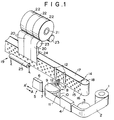
- Figure 1 is a perspective view showing an embodiment of the apparatus for feeding end securing tapes in accordance with the present invention.
- Figure 2 is a perspective view showing how a magic hand transfers an end securing tape.
- this embodiment comprises a folding roller 3, which forms a crease at a side edge part of an ordinary adhesive tape 2 when the adhesive tape 2 is unwound from an adhesive tape roll 1, and a folding plate 4, which folds the creased side edge part of the adhesive tape 2 such that an adhesive surface of the side edge part the adhesive tape 2 may be brought onto an adhesive surface of the remaining part of the adhesive tape 2.
- This embodiment also comprises a wind-up roller 8, which winds up the adhesive tape 2 having been folded in the manner described above, and a cutting machine 5, which cuts the adhesive tape 2 on the wind-up roller 8 and thereby prepares a plurality of end securing tapes 12, 12, ...
- This embodiment additionally comprises a magic hand 13, which transfers each end securing tape 12 from the wind-up roller 8, and a suction belt 14, which receives each end securing tape 12 from the magic hand 13 and conveys it into an end securing apparatus 19.
- the adhesive tape roll 1 is supported by a means (not shown) such that it can rotate around its axis of rotation.
- the leading end of the adhesive tape 2 is unwound from the adhesive tape roll 1 and wound up around the wind-up roller 8.
- the wind-up roller 8 is composed of a rotatable roller 10, which is supported on a drive means (not shown) and can rotate around its axis of rotation, and a fixed roller 9, which is located on the rotatable roller 10 and is fixed by a fixing means (not shown).
- a plurality of cutter blade receiving grooves 11, 11, ... are formed on the outer circumferential surface of the rotatable roller 10 in accordance with the width of each end securing tape 12.
- the outer circumferential surface of the rotatable roller 10 is constituted of a material, such as Teflon, from which the end securing tape 12 can be released easily.
- the adhesive tape 2 is wound around the outer circumferential surface of the wind-up roller 8.
- the side edge part of the adhesive tape 2 is creased by the folding roller 3.
- the folding roller 3 is supported such that it can rotate around its axis of rotation.
- the height of the folding roller 3 is smaller by a value equal to the width of the side edge, which is to be creased, than the height of the adhesive tape roll 1.
- the outer circumferential surface of the folding roller 3 is constituted of a material, from which the adhesive tape 2 can be released easily.
- the adhesive tape 2 threads at an angle of approximately 90° over the folding roller 3 and is thereby creased.
- the folding plate 4 is fixed such that it may be in slide contact with the adhesive tape 2.
- the folding plate 4 is provided with a plate, which is formed such that the folding angle on the side close to the folding roller 3 may be approximately 90°, the folding angle may increase gradually between the side close to the folding roller 3 and the side close to the wind-up roller 8, and the folding angle on the side close to the wind-up roller 8 may be approximately 180°.
- the side edge part of the adhesive tape 2 is folded gradually while the adhesive tape 2 is in slide contact with the folding plate 4 and is moving from the side of the folding roller 3 to the side of the wind-up roller 8.
- the cutting machine 5 comprises a cutter support 6, which is supported on a drive means (not shown) such that it can move in the directions indicated by the arrows A and A' in Figure 1, and a cutter 7, which is supported on the cutter support 6 such that it can move up and down in Figure 1.
- the cutter 7 moves up, and the cutter support 6 moves in the direction indicated by the arrow A.
- the cutter support 6 stops. Thereafter, the cutter 7 moves down and cuts the adhesive tape 2.
- the cutter support 6 moves in the direction indicated by the arrow A' and returns to its original position. The operations described above are repeated, and the plurality of the end securing tapes 12, 12, ... are thereby prepared sequentially.
- Each of the end securing tapes 12, 12, ... is transferred by the magic hand 13 from the wind-up roller 8 to the suction belt 14.
- the magic hand 13 is supported on a drive means (not shown) such that it can move between the wind-up roller 8 and the suction belt 14. As shown in detail in Figure 2, the magic hand 13 clamps the folded part of the end securing tape 12 and transfers the end securing tape 12 in the direction indicated by the arrow.
- the fixed roller 9 of the wind-up roller 8 is shaped in an approximately semicylindrical form such that the magic hand 13 can easily clamp the end securing tape 12.
- a discharging brush 26 should preferably be employed in order to discharge the end securing tape 12 when the end securing tape 12 is transferred from the wind-up roller 8 to the suction belt 14. In such cases, the lower edge part of the end securing tape 12 can be prevented from leaping, and the end securing tape 12 can be transferred smoothly.
- the suction belt 14 After receiving the end securing tape 12 from the magic hand 13, the suction belt 14 conveys the end securing tape 12 into the end securing apparatus 19.
- the suction belt 14 comprises an endless belt 16, which is mounted on a rotation shaft 18 supported on a drive means (not shown), and a suction box 17, which is located inside of the space defined by the endless belt 16.
- the endless belt 16 is provided with a plurality of suction holes 15, 15, ...
- the suction belt 14 supports the end securing tape 12 on the endless belt 16 by the air suction force of the suction box 17 and conveys the end securing tape 12 into the end securing apparatus 19. At this time, by adjusting the speed with which the rotation shaft 18 rotates, the intervals, at which the plurality of the end securing tapes 12, 12, ...
- the plurality of the end securing tapes 12, 12, ... can be fed appropriately such that end securing operations can be carried out simultaneously on a plurality of products in the end securing apparatus 19. Also, the feeding of the plurality of the end securing tapes 12, 12, ... can be adapted to a chance in the sizes of the products.
- a web is slit into three webs 20, 20, 20.
- the three webs 20, 20, 20 are wound up around cores 21, 21, 21, and three web rolls 22, 22, 22 are thereby obtained.
- the end securing operations are carried out simultaneously on the three web rolls 22, 22, 22.
- Figures 3A and 3B are side views showing how the end securing apparatus 19 operate.
- the end securing apparatus 19 comprises a pair of rotatable rollers 23, 23, which are supported on a drive means (not shown), a suction box 24, which is supported on one of the rotatable rollers 23, 23, and an end securing tape adhering roller 25, which is supported on a drive means (not shown).
- Each of the end securing tapes 12, 12, ... conveyed by the suction belt 14 stops at a predetermined position in the vicinity of the trailing end of the web 20 of each web roll 22. Thereafter, a pushing roller 25 moves in the direction indicated by the arrow D in Figure 3A. As shown in Figure 3B, the pushing roller 25 thus pushes the end of the web 20 of each web roll 22 against each end securing tape 12. In this manner, each end securing tape 12 is adhered to the end of the web 20 of each web roll 22.
- the pushing roller 25 moves in the direction indicated by the arrow E in Figure 3B.
- the rotatable rollers 23, 23 are again rotated, and each web roll 22 is rotated in the direction indicated by the arrow C in Figure 3B.
- the end of the web 20 of each web roll 22, to which the end securing tape 12 has been adhered is sandwiched between the rotatable rollers 23, 23 and the outer circumferential surface of the web roll 22 and is thereby secured to the outer circumferential surface of the web roll 22.
- the web roll 22 is then conveyed out of the end securing apparatus 19, and the suction box 24 moves in the direction indicated by the arrow F in Figure 3B to its original position.
- each end securing tape 12 can easily be adhered to a predetermined position on the end of the web 20 of each web roll 22.
- the apparatus for feeding end securing tapes in accordance with the present invention is not limited to the aforesaid embodiment, and may be embodied in various other ways.
- the end securing tapes 12, 12, ... are fed to the end securing apparatus 19, in which the web material is slit into three webs 20, 20, 20 and wound up as the three web rolls 22, 22, 22, and the end securing operations are carried out simultaneously on three web rolls 22, 22, 22.
- the web material may be slit into four or five webs.
- the end securing operations may be carried out for products other than the web rolls.
- any of other discharging means such as a discharging bar, may be employed.
- the end securing tapes 12, 12, ... are constituted of a material which is not easily charged electrostatically, the discharging brush 26 need not necessarily be employed.
- the non-adhesive surface is formed at the side edge part of the adhesive tape 2 by folding the side edge part.
- an adhesive tape may be employed which is already provided with such a non-adhesive surface.
- the apparatus for feeding end securing tapes in accordance with the present invention as defined by the claims can be embodied in various other ways such that the effects of the apparatus may not be lost.
Landscapes
- Replacement Of Web Rolls (AREA)
- Adhesive Tape Dispensing Devices (AREA)
Claims (11)
- Appareil d'alimentation en bandes de fixation d'extrémité, dans lequel plusieurs bandes de fixation d'extrémité sont avancées de manière séquentielle dans un appareil de fixation d'extrémité qui réalise de manière simultanée des opérations de fixation d'extrémité sur plusieurs produits,
l'appareil d'alimentation en bandes de fixation d'extrémité comportant :i) des moyens d'enroulement destinés à enrouler une bande adhésive, qui a une surface non adhésive au niveau d'une partie de bord latéral,ii) des moyens de coupe destinés à couper à une taille prédéterminée ladite bande adhésive, qui a été enroulée sur lesdits moyens d'enroulement, et destinés à former ainsi plusieurs bandes de fixation d'extrémité,iii) des moyens de transfert destinés à recevoir lesdites bandes de fixation d'extrémité, qui ont été formées par lesdits moyens de coupe, en provenance desdits moyens d'enroulement, et destinés à transférer les bandes de fixation d'extrémité reçues, etiv) des moyens de transport destinés à recevoir lesdites bandes de fixation d'extrémité à intervalles prédéterminés en provenance desdits moyens de transfert, et destinés à transporter lesdites bandes de fixation d'extrémité, qui ont été agencées suivant lesdits intervalles prédéterminés, dans l'appareil de fixation d'extrémité. - Appareil selon la revendication 1, dans lequel lesdits moyens d'enroulement sont constitués de telle sorte que ladite bande adhésive, qui présente la surface non adhésive au niveau de ladite partie de bord latéral, peut être enroulée sur la surface circonférentielle externe d'un rouleau qui peut tourner autour de son axe de rotation.
- Appareil selon la revendication 1, dans lequel lesdits moyens de coupe sont pourvus d'un couteau mobile.
- Appareil selon la revendication 1, dans lequel lesdits moyens de transfert sont pourvus d'une main magique.
- Appareil selon la revendication 1, dans lequel lesdits moyens de transport sont pourvus d'une bande à aspiration, sur laquelle lesdites bandes de fixation d'extrémité sont supportées à intervalles prédéterminés et qui transporte lesdites bandes de fixation d'extrémité dans ledit appareil de fixation d'extrémité.
- Appareil d'alimentation en bandes de fixation d'extrémité, dans lequel plusieurs bandes de fixation d'extrémité sont avancées de manière séquentielle dans un appareil de fixation d'extrémité qui réalise de manière simultanée des opérations de fixation d'extrémité sur plusieurs produits,
l'appareil d'alimentation en bandes de fixation d'extrémité comportant :i) des moyens de pliage destinés à plier une partie de bord latéral d'une bande adhésive de telle sorte qu'une surface adhésive de ladite partie de bord latéral peut être amenée sur une surface adhésive de la partie restante de ladite bande adhésive, ledit pliage étant réalisé lorsque ladite bande adhésive est déroulée d'un rouleau de ladite bande adhésive,ii) des moyens d'enroulement destinés à enrouler ladite bande adhésive, dont ladite partie de bord latéral a été pliée par lesdits moyens de pliage,iii) des moyens de coupe destinés à couper à une taille prédéterminée ladite bande adhésive pliée, qui a été enroulée sur lesdits moyens d'enroulement, et destinés à former ainsi plusieurs bandes de fixation d'extrémité,iv) des moyens de transfert destinés à recevoir lesdites bandes de fixation d'extrémité, qui ont été formées par lesdits moyens de coupe, en provenance desdits moyens d'enroulement, et destinés à transférer les bandes de fixation d'extrémité reçues, etv) des moyens de transport destinés à recevoir lesdites bandes de fixation d'extrémité à intervalles prédéterminés en provenance desdits moyens de transfert, et destinés à transporter lesdites bandes de fixation d'extrémité, qui ont été agencées suivant lesdits intervalles prédéterminés, dans l'appareil de fixation d'extrémité. - Appareil selon la revendication 6, dans lequel lesdits moyens de pliage sont constitués de telle sorte qu'ils peuvent être en contact coulissant avec ladite partie de bord latéral de ladite bande adhésive et peuvent plier progressivement ladite partie de bord latéral.
- Appareil selon la revendication 6, dans lequel lesdits moyens d'enroulement sont constitués de telle sorte que ladite bande adhésive, qui présente la surface non adhésive au niveau de ladite partie de bord latéral, peut être enroulée sur la surface circonférentielle externe d'un rouleau qui peut tourner autour de son axe de rotation.
- Appareil selon la revendication 6, dans lequel lesdits moyens de coupe sont pourvus d'un couteau mobile.
- Appareil selon la revendication 6, dans lequel lesdits moyens de transfert sont pourvus d'une main magique.
- Appareil selon la revendication 6, dans lequel lesdits moyens de transport sont pourvus d'une bande à aspiration, sur laquelle lesdites bandes de fixation d'extrémité sont supportées à intervalles prédéterminés et qui transporte lesdites bandes de fixation d'extrémité dans ledit appareil de fixation d'extrémité.
Applications Claiming Priority (2)
| Application Number | Priority Date | Filing Date | Title |
|---|---|---|---|
| JP2319724A JP2571151B2 (ja) | 1990-11-22 | 1990-11-22 | 端末止めテープ供給装置 |
| JP319724/90 | 1990-11-22 |
Publications (2)
| Publication Number | Publication Date |
|---|---|
| EP0487107A1 EP0487107A1 (fr) | 1992-05-27 |
| EP0487107B1 true EP0487107B1 (fr) | 1995-04-05 |
Family
ID=18113464
Family Applications (1)
| Application Number | Title | Priority Date | Filing Date |
|---|---|---|---|
| EP91119976A Expired - Lifetime EP0487107B1 (fr) | 1990-11-22 | 1991-11-22 | Dispositif pour l'alimentation des bandes de fixation |
Country Status (4)
| Country | Link |
|---|---|
| US (1) | US5225029A (fr) |
| EP (1) | EP0487107B1 (fr) |
| JP (1) | JP2571151B2 (fr) |
| DE (1) | DE69108681T2 (fr) |
Families Citing this family (13)
| Publication number | Priority date | Publication date | Assignee | Title |
|---|---|---|---|---|
| US5256232A (en) * | 1992-07-27 | 1993-10-26 | Eastman Kodak Company | Apparatus and method for winding strips of web material onto spools |
| DE4425405C2 (de) * | 1994-07-19 | 1997-10-02 | Fischer Maschf Karl E | Vorrichtung zum Überschieben klebriger Streifen, insbesondere Cordbandstreifen |
| US5555978A (en) * | 1995-10-05 | 1996-09-17 | Elsner Engineering Works, Inc. | Wound roll and closure strip assembly |
| US6095218A (en) * | 1997-07-16 | 2000-08-01 | New Jersey Machine, Inc. | Transfer system for transporting articles cut from a blank of material |
| JP3887707B2 (ja) | 1998-05-07 | 2007-02-28 | 株式会社イソワ・フーパースイフト | 自動テープ貼付け方法および装置 |
| FR2827972B1 (fr) | 2001-07-25 | 2003-10-03 | Eastman Kodak Co | Dispositif d'application de bandes adhesives a eliminateur rigide de charge electrostatique |
| JP3926149B2 (ja) | 2001-12-25 | 2007-06-06 | 富士フイルム株式会社 | ロール状物の自動包装方法およびシステム |
| JP4743051B2 (ja) * | 2006-09-05 | 2011-08-10 | 川上産業株式会社 | シート状物のコイルの末端をテープ止めする装置および方法 |
| FI121305B (fi) * | 2007-06-05 | 2010-09-30 | Metso Paper Inc | Menetelmä pituusleikkurin käyttämiseksi ja liima-aineen applikointilaitteisto |
| EP3022143B1 (fr) * | 2013-07-08 | 2018-10-03 | Valmet Technologies, Inc. | Procédé et ensemble pour fixer l'extrémité d'un rouleau de bande |
| FI126888B (en) * | 2016-06-17 | 2017-07-14 | Valmet Technologies Oy | Method for Attaching the End of a Fiber Web to a Fiber Roll and a Clamping Distribution System for Attaching a Fiber End to a Fiber Roll in a Winder |
| CN110239989B (zh) * | 2019-06-20 | 2024-05-31 | 江苏嘉拓新能源智能装备股份有限公司 | 多功能卷材尾边自动冲孔、贴合、备胶、裁切装置及方法 |
| CN116946770B (zh) * | 2023-08-11 | 2026-01-30 | 铜陵方正塑业科技有限公司 | 一种吹膜机用塑料袋收卷装置 |
Family Cites Families (9)
| Publication number | Priority date | Publication date | Assignee | Title |
|---|---|---|---|---|
| US2681702A (en) * | 1949-03-22 | 1954-06-22 | Owens Corning Fiberglass Corp | Method of packaging insulating strips |
| US3420723A (en) * | 1964-11-30 | 1969-01-07 | Smyth Mfg Co | Method of forming and applying tubular back linings to fillers |
| BE791462A (fr) * | 1971-12-04 | 1973-03-16 | Jagenberg Werke Ag | Machine a etiqueter pour bouteilles ou objets similaires, avec un dispositif pour en enrober d'une feuille metallique les goulots oules tetes |
| JPS50121698A (fr) * | 1974-03-12 | 1975-09-23 | ||
| DE3019506C2 (de) * | 1980-05-22 | 1983-12-22 | Max H. 4901 Hiddenhausen Klinger | Etikettiervorrichtung |
| US4588463A (en) * | 1982-11-04 | 1986-05-13 | Datafile Limited | Method of producing a reinforced file folder |
| JPS60128155A (ja) * | 1983-12-08 | 1985-07-09 | Mitsubishi Heavy Ind Ltd | 巻取ロ−ルの紙端テ−プ貼り方法 |
| JPS615973A (ja) * | 1984-06-20 | 1986-01-11 | Matsushita Electric Ind Co Ltd | 平面走査型プリンタ |
| US5030311A (en) * | 1989-10-02 | 1991-07-09 | Eastman Kodak Company | Method and apparatus for taping lead and tail ends of web during winding onto a core |
-
1990
- 1990-11-22 JP JP2319724A patent/JP2571151B2/ja not_active Expired - Fee Related
-
1991
- 1991-11-22 EP EP91119976A patent/EP0487107B1/fr not_active Expired - Lifetime
- 1991-11-22 DE DE69108681T patent/DE69108681T2/de not_active Expired - Lifetime
- 1991-11-22 US US07/796,356 patent/US5225029A/en not_active Expired - Lifetime
Also Published As
| Publication number | Publication date |
|---|---|
| US5225029A (en) | 1993-07-06 |
| JP2571151B2 (ja) | 1997-01-16 |
| JPH04189243A (ja) | 1992-07-07 |
| DE69108681T2 (de) | 1995-08-17 |
| DE69108681D1 (de) | 1995-05-11 |
| EP0487107A1 (fr) | 1992-05-27 |
Similar Documents
| Publication | Publication Date | Title |
|---|---|---|
| EP0487107B1 (fr) | Dispositif pour l'alimentation des bandes de fixation | |
| US5885391A (en) | Tape roll liner/tab application apparatus and method | |
| EP0538052A1 (fr) | Machine pour rebobiner et en même temps traiter un matériau mince et flexible en utilisant un convoyeur | |
| US4964585A (en) | Slitting and rewiding machine | |
| EP2266904B1 (fr) | Rouleau de feuilles avec noyau de renforcement de bobine, appareil pour enrouler le rouleau et procédé | |
| AU610330B2 (en) | Roll-cutting machine | |
| US5346150A (en) | Tail gap winder | |
| CA2489281A1 (fr) | Appareil de formation d'un rouleau de ruban d'elimination de contaminants et procedes de formation de rouleaux de ruban d'elimination de contaminants | |
| KR100548751B1 (ko) | 단일 스테이션의 연속 로그 롤 와인더 | |
| JP2002505988A (ja) | 相互に接触する多数の物品を互いに分離させる装置 | |
| CA2221182A1 (fr) | Mandrin et procede de bobinage pour ruban adhesif sans tube | |
| EP3988484B1 (fr) | Procédé et appareil de préparation de bords de bobines de matériau en bande | |
| PL180707B1 (pl) | Urzadzenie do wytwarzania zwojów z arkuszy ciasta i arkuszy dzielacych PL PL PL PL PL | |
| US4082599A (en) | Splicing roller device for automatic paper splicing apparatus | |
| CN119822115B (zh) | 窄带的分切收卷装置 | |
| JPH0724224Y2 (ja) | 帯状紙材の耳切取り装置 | |
| JPS63312098A (ja) | 連続裁断装置 | |
| CN121158583A (zh) | 一种模块化设计纸张分切机 | |
| JPH03223054A (ja) | スリッターリワインダー | |
| JP3188523B2 (ja) | 折畳みウエブ製造機 | |
| JPS63310446A (ja) | 枚葉シートの集積搬出装置 | |
| CA2221334C (fr) | Piece adhesive/languette pour un rouleau d'adhesif, dispositif et procede d'application | |
| JPS63315457A (ja) | 枚葉シートのオーバーラップ装置 | |
| EP0125863A1 (fr) | Procédé pour fabriquer des sacs, sachets et similaires | |
| JP2750546B2 (ja) | スリッターリワインダー |
Legal Events
| Date | Code | Title | Description |
|---|---|---|---|
| PUAI | Public reference made under article 153(3) epc to a published international application that has entered the european phase |
Free format text: ORIGINAL CODE: 0009012 |
|
| AK | Designated contracting states |
Kind code of ref document: A1 Designated state(s): DE GB NL |
|
| 17P | Request for examination filed |
Effective date: 19921125 |
|
| 17Q | First examination report despatched |
Effective date: 19940517 |
|
| GRAA | (expected) grant |
Free format text: ORIGINAL CODE: 0009210 |
|
| AK | Designated contracting states |
Kind code of ref document: B1 Designated state(s): DE GB NL |
|
| PG25 | Lapsed in a contracting state [announced via postgrant information from national office to epo] |
Ref country code: NL Free format text: LAPSE BECAUSE OF NON-PAYMENT OF DUE FEES Effective date: 19950405 |
|
| REF | Corresponds to: |
Ref document number: 69108681 Country of ref document: DE Date of ref document: 19950511 |
|
| NLV1 | Nl: lapsed or annulled due to failure to fulfill the requirements of art. 29p and 29m of the patents act | ||
| PLBE | No opposition filed within time limit |
Free format text: ORIGINAL CODE: 0009261 |
|
| STAA | Information on the status of an ep patent application or granted ep patent |
Free format text: STATUS: NO OPPOSITION FILED WITHIN TIME LIMIT |
|
| 26N | No opposition filed | ||
| REG | Reference to a national code |
Ref country code: GB Ref legal event code: IF02 |
|
| REG | Reference to a national code |
Ref country code: GB Ref legal event code: 732E |
|
| PGFP | Annual fee paid to national office [announced via postgrant information from national office to epo] |
Ref country code: DE Payment date: 20101027 Year of fee payment: 20 |
|
| PGFP | Annual fee paid to national office [announced via postgrant information from national office to epo] |
Ref country code: GB Payment date: 20101117 Year of fee payment: 20 |
|
| REG | Reference to a national code |
Ref country code: DE Ref legal event code: R071 Ref document number: 69108681 Country of ref document: DE |
|
| REG | Reference to a national code |
Ref country code: DE Ref legal event code: R071 Ref document number: 69108681 Country of ref document: DE |
|
| REG | Reference to a national code |
Ref country code: GB Ref legal event code: PE20 Expiry date: 20111121 |
|
| PG25 | Lapsed in a contracting state [announced via postgrant information from national office to epo] |
Ref country code: GB Free format text: LAPSE BECAUSE OF EXPIRATION OF PROTECTION Effective date: 20111121 |
|
| PG25 | Lapsed in a contracting state [announced via postgrant information from national office to epo] |
Ref country code: DE Free format text: LAPSE BECAUSE OF EXPIRATION OF PROTECTION Effective date: 20111123 |