EP0487206A1 - Gerät zur Detektion der Position eines Lichtpunktes - Google Patents
Gerät zur Detektion der Position eines Lichtpunktes Download PDFInfo
- Publication number
- EP0487206A1 EP0487206A1 EP91309660A EP91309660A EP0487206A1 EP 0487206 A1 EP0487206 A1 EP 0487206A1 EP 91309660 A EP91309660 A EP 91309660A EP 91309660 A EP91309660 A EP 91309660A EP 0487206 A1 EP0487206 A1 EP 0487206A1
- Authority
- EP
- European Patent Office
- Prior art keywords
- light spot
- difference
- output
- recording
- light
- Prior art date
- Legal status (The legal status is an assumption and is not a legal conclusion. Google has not performed a legal analysis and makes no representation as to the accuracy of the status listed.)
- Granted
Links
- 230000003287 optical effect Effects 0.000 claims abstract description 28
- 238000006243 chemical reaction Methods 0.000 claims description 21
- 230000003321 amplification Effects 0.000 claims description 3
- 238000003199 nucleic acid amplification method Methods 0.000 claims description 3
- 230000009191 jumping Effects 0.000 abstract description 6
- 238000000034 method Methods 0.000 description 46
- 238000001514 detection method Methods 0.000 description 18
- 238000010586 diagram Methods 0.000 description 8
- PRKWNRUVAZZHPH-UHFFFAOYSA-N 2-(4-chlorophenyl)sulfonyl-6-methoxy-3-nitropyridine Chemical compound COC1=CC=C([N+]([O-])=O)C(S(=O)(=O)C=2C=CC(Cl)=CC=2)=N1 PRKWNRUVAZZHPH-UHFFFAOYSA-N 0.000 description 7
- 101000606504 Drosophila melanogaster Tyrosine-protein kinase-like otk Proteins 0.000 description 3
- 238000009826 distribution Methods 0.000 description 3
- 102100028777 AP-1 complex subunit sigma-1A Human genes 0.000 description 2
- 101100204393 Arabidopsis thaliana SUMO2 gene Proteins 0.000 description 2
- 101000768000 Homo sapiens AP-1 complex subunit sigma-1A Proteins 0.000 description 2
- 101150112492 SUM-1 gene Proteins 0.000 description 2
- 101150096255 SUMO1 gene Proteins 0.000 description 2
- 101100311460 Schizosaccharomyces pombe (strain 972 / ATCC 24843) sum2 gene Proteins 0.000 description 2
- 230000008859 change Effects 0.000 description 2
- 230000004048 modification Effects 0.000 description 2
- 238000012986 modification Methods 0.000 description 2
- 230000002093 peripheral effect Effects 0.000 description 2
- 230000003247 decreasing effect Effects 0.000 description 1
- 230000001934 delay Effects 0.000 description 1
- 230000004069 differentiation Effects 0.000 description 1
- 230000000694 effects Effects 0.000 description 1
- 230000006872 improvement Effects 0.000 description 1
- 230000004044 response Effects 0.000 description 1
- 238000005070 sampling Methods 0.000 description 1
- 239000004576 sand Substances 0.000 description 1
Images




Classifications
-
- G—PHYSICS
- G11—INFORMATION STORAGE
- G11B—INFORMATION STORAGE BASED ON RELATIVE MOVEMENT BETWEEN RECORD CARRIER AND TRANSDUCER
- G11B7/00—Recording or reproducing by optical means, e.g. recording using a thermal beam of optical radiation by modifying optical properties or the physical structure, reproducing using an optical beam at lower power by sensing optical properties; Record carriers therefor
- G11B7/08—Disposition or mounting of heads or light sources relatively to record carriers
- G11B7/09—Disposition or mounting of heads or light sources relatively to record carriers with provision for moving the light beam or focus plane for the purpose of maintaining alignment of the light beam relative to the record carrier during transducing operation, e.g. to compensate for surface irregularities of the latter or for track following
- G11B7/0901—Disposition or mounting of heads or light sources relatively to record carriers with provision for moving the light beam or focus plane for the purpose of maintaining alignment of the light beam relative to the record carrier during transducing operation, e.g. to compensate for surface irregularities of the latter or for track following for track following only
- G11B7/0903—Multi-beam tracking systems
-
- G—PHYSICS
- G11—INFORMATION STORAGE
- G11B—INFORMATION STORAGE BASED ON RELATIVE MOVEMENT BETWEEN RECORD CARRIER AND TRANSDUCER
- G11B7/00—Recording or reproducing by optical means, e.g. recording using a thermal beam of optical radiation by modifying optical properties or the physical structure, reproducing using an optical beam at lower power by sensing optical properties; Record carriers therefor
- G11B7/08—Disposition or mounting of heads or light sources relatively to record carriers
- G11B7/09—Disposition or mounting of heads or light sources relatively to record carriers with provision for moving the light beam or focus plane for the purpose of maintaining alignment of the light beam relative to the record carrier during transducing operation, e.g. to compensate for surface irregularities of the latter or for track following
- G11B7/0943—Methods and circuits for performing mathematical operations on individual detector segment outputs
Definitions
- the present invention relates to an apparatus for detecting a position of a light spot in an optical disk, and more particularly to an apparatus for detecting a position of a light spot suitable for a tracking servo control or a track-jumping operation control of an optical memory disk (hereinafter referred to as an OMD).
- an OMD optical memory disk
- on-track detection detection as to wether or not a light spot for reading information exists on the axis of the recording track of the optical disk (hereinafter referred to as on-track detection) is conducted generally by using the method called the 3-light-beam method or the push-pull method.
- a preceding light spot and a succeeding light spot are irradiated at the positions preceding and succeeding to a light spot of a main light beam for recording and reading information with the same predetermined spacings in direction of the center line of the recording track and with another predetermined spacings in a direction perpendicular to the center line direction of recording tracks (travelling direction of the light beam) with respect to the light spot preceding light spot and the succeeding light spot are such that the same spacings are provided in directions opposite to each other with respect to the center line of the recording track in a manner that it is put therebetween.
- a reflected light beam from the preceding light spot is detected by a first photodetector
- a reflected light beam from the succeeding light spot is detected by a second photodetector
- a light spot from the main light beam is detected by a third photodetector.
- this difference output TE a is called a tracking error signal.
- the above mentioned on-track detection can be carried out by the 3-light-beam method only in connection with an optical disk exclusive for reproduction.
- an optical disk exclusive for reproduction there is a small quantity of reflected light at the portion of the recording track because pit trains where information signals are stored are recorded, whereas there is a great quantity of reflected light at the portions except for the recording track because they are subjected to mirror finish. Accordingly, values of TE a which are not equal to zero are provided.
- the push-pull method is known as the method permitting the on-track detection.
- a bisected or half-split photodetector is used.
- the zero-th order reflected light and ⁇ 1-st order reflected light are produced.
- these rays of the reflected light are emitted onto the photodetector, the portion having a relatively high light intensity and the portion having a relatively low light intensity are produced.
- This system uses three light beam spots in the same manner as in the case of the 3-light-beam method.
- the preceding light spot and the succeeding light spot are both emitted also onto recording tracks TR i+1 and TR i ⁇ 1 adjacent to the both sides of the recording track TR i on which the main light spot exists. Namely, a portion of a light at the outer periphery of the preceding light spot is emitted also onto the recording track TR i+1 .
- a portion of a light at the outer periphery thereof is also on the recording track TR i ⁇ 1. Reflected light beams from the respective light spots are detected by the three half-split photodetectors.
- the present invention has been made for the purpose of an improvement on the 3-push-pull method in the conventional form, and its object is to provide an apparatus for detecting a position of a light spot in which the improved 3-push-pull method is used to permit the on-track detection without hindrance even at the no information recorded portion of an optical disk, and to permit the on-track detection without hindrance even at the time of recording information onto an optical disk.
- an apparatus for detecting a position of a light spot in which a reflected light beam from a signal recording surface of an optical disk is used to detect whether or not the light spot exists on the center line of a recording track of the optical disk comprising: a light emitting unit for emitting, onto the signal recording surface, a first light spot, a second light spot located at a position preceding to the first light spot with a first predetermined spacing in a direction of the center line of the recording track and with a second predetermined spacing from adjacent tracks in a direction perpendicular to the center line of the recording track so that no light beam is emitted thereonto, and a third light spot located at a position succeeding to the first light spot with the same spacing as the first predetermined spacing in a direction of the center line of recording track and with the same spacing as the second predetermined spacing on the opposite to the second light spot in a direction perpendicular to the center line of the recording track; a first photodete
- the second predetermined spacing may be substantially one fourth of the distance between axes of the adjacent recording tracks.
- the second light spot is emitted at a position such that no light beam is emitted onto recording tracks adjacent in a direction perpendicular to the center line of the recording track, and the third light spot is emitted with the same spacing as in the case of the second light spot on the opposite side to the second light spot with respect to the recording track.
- the difference output (push-pull output) TE s1 of the second light spot and the difference output (push-pull output) TE s2 of the third light spot.
- the first light spot position signal TE1 TE M - (K/2) x (TE s1 + TE s2 )
- TE M represents a first difference output
- K/2 represents a predetermined real number
- the second light spot position signal TE2 T s1 - T s2 it can be discriminated that only when TE1 is equal to zero and TE2 takes a predetermined value,there results the on-track state. Since there dose not result the on-track state when TE2 takes other values even if TE1 is equal to zero, discrimination is easily carried out.
- the above mentioned second predetermined spacing is set to substantially one fourth of the distance between axes of the adjacent recording tracks, it is indicated that when TE1 is equal to zero and TE2 takes a negative maximal value, there results the on-track state.
- an apparatus for detecting a position of a light spot in which a reflected light beam from a signal recording surface of an optical disk is used to detect whether or not the light spot exists on a center line of the recording track of the optical disk comprising: a light emitting unit for emitting, onto the signal recording surface, a first light spot, a second light spot located at a position preceding to the first light spot with a first predetermined spacing in a direction of the center line of the recording track and with a second predetermined spacing from adjacent tracks in a direction perpendicular to the center line of the recording track, and a third light spot located at a position succeeding to the first light spot with the first predetermined spacing in a direction of the center line of the recording track and with the second predetermined spacing on the opposite side to the second light spot in a direction perpendicular to the center line of the recording track; a first photodetection unit including bisected detector surfaces, and for applying photoelectric conversion to a
- the operation unit may be constructed as follows. Namely, in the case where the first light spot position signal on the recording track is placed in the non-recording state, after the time required until the light spot moves by a distance between the center of the first light spot and that of the third light spot has passed from the above time point when the position of the first light spot is placed in the non-recording state, the operation unit samples and holds the third difference output to generate the fourth difference output, thus to calculate the first and the second light spot position signals.
- the operation unit may hold a peak level of the third difference output to generate the fourth difference output, thus to calculate the first and the second light spot position signals.
- the operation unit may amplify the low frequency band component of the third difference output at a predetermined amplification factor to generate the fourth difference output, thus to calculate the first and the second light spot position signals.
- ⁇ is a distance between the center of the first light spot and that of the third light spot
- v is a speed of a light spot moving on the recording track.
- an approach may be employed to peak-hold the third difference output TE s2 to thereby correct a photoelectric output changed by a difference between a quantity of a reflected light at the non-recorded portion and that at the recorded portion, thus making it possible to use it as the fourth difference output.
- the operation unit can calculate the first and the second light spot position signals TE1 and TE2 without hindrance.
- an approach may be employed to extract the low frequency band component of the third difference output, thereby making it possible to provide a mean value of photoelectric outputs changed due to the radio frequency.
- the level of this mean value is lowered to some extent as compared to the third difference output which does not undergo changes due to the radio frequency, if that mean value is amplified at a predetermined amplification factor, the operation unit can calculate the first and the second light spot position signals TE1 and TE2 without hindrance.
- an approach may be employed to take a sum output of the two electric signals from the respective detector surfaces of the second photo detection unit to obtain a second sum output, to take a sum output of the two electric signals from the respective detector surfaces of the the third photodetection unit to obtain a third sum output, and to take a difference between the second and third sum outputs, thereby making it possible to easily use this apparatus as an apparatus for detecting a light spot position based on the ordinary 3-light-beam method.
- FIG. 13(A) The principle of the 3-light-beam method is shown in FIG. 13.
- a preceding light spot LB s1 and a succeeding light spot LB s2 are irradiated at positions preceding and succeeding to a light spot LB M of a main light beam for recording and reading information with the same predetermined spacings in a direction of a recording track center line AX, and with another spacing ⁇ in a direction perpendicular to the center line direction TD (travelling direction of the light beam) of the recording track TR.
- the preceding light spot LB s1 and the succeeding light spot LB s2 are such that spacings ⁇ are provided in directions opposite to each other with respect to the center line of the recording track TR.
- a ref1ected light beam from the preceding light spot LB s1 is detected by a first photodetector A
- a reflected light beam from the succeeding light spot LB s2 is detected by a second photodetector B
- a light spot LB M of a main light beam is detected by a third photodetector C.
- an electric output S s1 from the detector surface A and an electric output S s2 from the detector surface B which have been subjected to photoelectric conversion at the respective detector surfaces are inputted to a subtraction circuit SB.
- the positional control of a light spot in the track jumping can be conducted.
- this difference output TE a is called a tracking error.
- the above-mentioned on-track detection can be carried out by the 3-light-beam method only in connection with an optical disk exclusive for reproduction.
- an optical disk exclusive for reproduction as shown in FIG. 13(A), since pit trains where information signals are stored are recorded at the portion of recording track TR indicated by white ground, a quantity of reflected light is smaller than that at the portion subjected to mirror finish processing indicated by the sand pattern in the figure. Thus, TE a values which are not equal to zero are provided.
- the push-pull method As the method permitting the on-track detection even in such a case, the push-pull method is known.
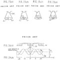
- the principle of the push-pull method will be described with reference to FIGS. 14, 15, 16 and 17.
- a bisected photodetector PD is used.
- the zero-th order reflected light L0 and ⁇ 1-st order reflected light L1 are produced.
- the signal intensity distribution is as shown, i.e., a portion S0 having relatively high eight intensity and a portion S1 having a relatively low light intensity are produced.
- the output terminals of the detector surfaces A and B are connected to the input terminal of the subtracter in the same manner as in the case of FIG. 13 to take a difference output, since the distributions of the portions S0 and S1 are symmetrical with respect to the detector surface divisional line in FIG. 14, the value of the difference output becomes equal to zero.
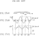
- the distributions of the 0-th order reflected light L0 and the 1-st order reflected light L1 are shown in a model form in FIGS.
- FIG. 16 is a view showing an output S A from the detector surface A and an output S B from the detector surface B in a radial direction of the disk in which the x-axis coincides with the radial direction of the disk.
- 2 ⁇ represents a phase difference between S A and S B .
- S A and S B form sinusoidal curves which are the same in the amplitude and the wavelength, but only different in the phase wherein "a” represents an amplitude of the sinusoidal curve and "I” is an output value indicating the center of the amplitude of the sinusoidal curve.
- This system uses three light beam spots LB M , LB s1 and LB s2 .
- the preceding and succeeding light spot LB s1 and LB s2 are both emitted also onto recording tracks TR i+1 and TR i ⁇ 1 adjacent to the recording track TR i on which the main light spot LB M exists. Namely, a portion of a light at the outer periphery of the preceding light spot is also emitted onto the recording track TR i+1 .
- the succeeding light spot light LB s2 a portion of a light at the outer periphery thereof is also emitted onto the recording track TR i ⁇ 1.
- reflected beams from the light spots are detected by three half-split photodetectors, and difference outputs are provided on the basis of the push-pull method, respectively.
- the push-pull difference output of the main light spot LB M the push-pull difference output of the preceding light spot LB s1 and the push-pull difference of the succeeding light spot LB s2 are designated by TE M , TE s1 and TE s2 , respectively, outputs as shown in FIGS 21 (C), (B) and (D) are provided.
- K represents a ratio between a quantity of reflected light from the main light spot LB M and an intensity of reflected light from the preceding or succeeding light spot.
- the output TE d becomes equal to zero as shown in FIG. 21(E). Accordingly, the tracking control can be carried out also at the non-recorded track portion without undergoing the influence of offset.
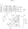
- an apparatus for detecting a position of a light spot designated by a reference numeral 100 is directed to a light spot position detector in which a reflected light beam from the signal recording surface RS of an optical disk D is used to detect whether or not a light spot exists on the axis of a recording track.
- this apparatus comprises: a light emitting unit R for emitting, onto the signal recording surface RS, a first light spot LB M , a second light spot LB s1 located at a position preceding to the first light spot LB M with a predetermined spacing in a direction of the center line of the recording track TR and with a another predetermined spacing from adjacent tracks in a direction perpendicular to the center line of the recording track so that no light is emitted onto the adjacent tracks, and a third light spot LB s2 located at a position succeeding to the first light spot with a predetermined spacing in a direction of the recording track axis with respect to the first light spot LB M and with the other spacing on the opposite side to the second light spot LB s1 in a direction perpendicular to the center line of the recording track; a first photodetection unit PD M including bisected detector surfaces A M and B M , and for applying photoelectric conversion to a reflected light beam from the first light spot LB M to output two electric
- the second light spot LB s1 is irradiated at a position where no light is emitted onto recording tracks TR i+1 and TR i ⁇ 1 adjacent in a direction perpendicular to the center line of the recording track TR i
- the third light spot LB s2 is irradiated with the same spacing as in the case of the second light spot LB S1 on the opposite side to the second light spot LB s1 with respect to the center line of or the recording track TR i .
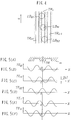
- the difference output (push-pull output) TE s1 of the second light spot and the difference output (push-pull output) TE s2 of the third light spot are not the same in phase as in the case of the conventional form shown in FIGS. 21(B) and (D), but are out of phase, e.g., as shown in FIGS. 5(B) and (D).
- the first light spot position signal TE1 TE M - (K/2) x (TE s1 + TE s2 )
- TE M represents a first difference output and K/2 represents a predetermined real number.
- TE2 TE s1 - TE s2 it can be discriminated that only when TE1 is equal to zero and TE2 takes a predetermined value, there results the on-track state. Since there does not result the on-track state when TE2 takes other values even if TE1 is equal to zero, discrimination is easily carried out.
- K represents a ratio between a push-pull difference output from the main light spot and a mean value of push-pull outputs from the preceding and succeeding light spots in the on-track state. Namely, in the on-track state, K is represented by 2 x TE M /(TE s1 + TE s2 ).
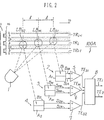
- FIG. 2 shows the configuration of a first embodiment.
- An apparatus for detecting a position of a light spot designated by a reference numeral 100A comprises a laser light source 1 serving as an emitting means, a bisected photodetector 3 serving as a first photodetection means, a bisected photodetector 2 serving as a second photodetection means, a bisected photodetector 4 serving as a third photodetection means, subtracters 5, 6 and 7, and an operation circuit 8.
- the subtracters 5, 6 and 7 and the operation circuit 8 constitute an operation means.
- the laser light source 1 is comprised of optical parts such as a laser diode, a lens, or a half-mirror (not shown), etc. and emits a light spot as shown onto the recording track TR i on the signal recording surface of OMD.
- a main light spot LBM serving as a first light spot is emitted onto the center line of the recording track (groove) TR i .
- the preceding light spot LB s1 serving as the second light spot is emitted at a position preceding by a predetermined interval or a first predetermined spacing l in a direction of the recording track center line from the main light spot LB M and spaced by a distance or a second predetermined spacing b/2 on the recording track TR i+1 side in a direction perpendicular to the recording track center line.
- the respective recording track widths and the widths of the portions outside the recording tracks are equal to each other.
- Each width is b.
- the diameter of the light spot is designated by 2b. Accordingly, as shown in FIG.
- the succeeding light spot LB s2 serving as the third light spot is irradiated at a position succeeding by an interval or spacing D in a direction of the recording track center line from the main light spot LB M , and spaced by a fixed distance or a second predetermined spacing b/2 on the recording track TR i ⁇ 1 side in a direction perpendicular to the recording track center line.
- An arrangement is employed such that the outer peripheral portion of a light of the succeeding light spot is not also emitted onto the adjacent recording track TR i ⁇ 1.
- the bisected photodetector 3 includes detector surfaces A M and B M in such a manner that the direction of the divisional line of the detector surface is in parallel to the direction of the recording track center line.
- the output terminal of the detector surface A M is connected to the negative side input terminal of the subtracter 6, and the output terminal of the detector surface B M is connected to the positive side input terminal of the subtracter 6.
- the bisected photodetector 2 includes detector surfaces A1 and B1 in such a manner that the direction of the divisional line of the detector surface is in parallel to the direction of the recording track center line.
- the output terminal of the detector surface A1 is connected to the negative input terminal of the subtracter 5, and the output terminal of the detector surface B1 is connected to the positive side input terminal of the subtracter 5.
- the bisected photodetector 4 is of a structure including detector surfaces A2 and B2 and such that the direction of the divisional line of the detector surface is in parallel to the direction of the recording track center line.
- the output terminal of the detector surface A2 is connected to the negative side input terminal of the subtracter 7 and the output terminal of the detector surface B2 is connected to the positive input side terminal of the subtracter 7.
- FIG. 5(C) shows a graphical representation of a curve of the difference output (push-pull output) TE M with the radial direction of the disk axis being coincident with the x-axis. This curve is a sinusoidal curve. In this case, an offset 2 ⁇ I is produced.
- FIG. 5 (B) is a graphical representation of a curve of the difference output (push-pull output) TE s1 with the radial direction being coincident with the x-axis. This curve is a sinusoidal curve different from TE M only in the phase.
- FIG.5(D) is a graphical representation of a curve of this difference output (push-pull output) TE s2 with radial direction of the disk being coincident with the x-axis.
- This curve is a sinusoidal curve different from TE M only in the phase.
- a phase difference 180 degrees between the difference outputs TE s1 and TE s2 .
- TE1 TE M - (K/2) x (TE s1 + TE s2 )
- TE2 TE s1 - TE s2
- K represents a ratio between a push-pull difference output from the main light spot LB M and a mean value of push-pull difference outputs from the preceding and succeeding light spots in the on-track state.
- K is represented by the relationship expressed as 2 x TE M /(TE s1 + TE s2 ).
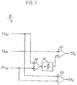
- this operation circuit 8 includes an adder 20, a multiplier 21, and subtracters 22 and 23 connected as shown, and has a structure such that respective push-pull difference outputs TE M , TE s1 and TE s2 are inputted as shown.
- the value of multiplier factor K/2 multiplied in the multiplier 21 is set to a quotient (real number) which is gotten when TE M is divided by a mean value of TE s1 and TE s2 in the on-track state as described above.
- the configuration of the second embodiment is shown in FIG. 6.
- the second embodiment has the configuration that, in the light spot position detecting apparatus 100A of FIG. 2, a sample-and-hold circuit 10 is provided between the subtracter 7 and the operation circuit 8, and that a timing control circuit 9 is connected to the sample-and-hold circuit 10.
- a EFM (eight to fourteen modulation) signal SW for writing information is inputted to the timing control circuit 9.
- This write EFM signal S W is obtained from an information signal RF read by the main light spot LB M .
- l is a distance between the center of the main light spot LB M and that of the succeeding light spot LB s2
- v is a speed of the light spot moving on the recording track.
- the sample-and-hold circuit 10 samples and holds, by a control signal S C1 , a difference output TE s2 inputted from the subtracter 7 to output it as an output SH10 to the operation circuit 8.
- the output SH10 corresponds to a fourth difference output.
- the operation circuit 8 uses the output SH10 in place of the difference output TE s2 to perform the calculation expressed by the above equations (18) and (19), thus to output outputs TE1 and TE2.
- FIG. 8 shows the further detailed configuration of the timing control circuit 9.
- the timing control circuit 9 is of a structure including a delay circuit 13 and a differentiating circuit 14 connected in series.
- the delay circuit 13 receives a write EFM signal S W to output a delay signal S13 to the differentiating circuit 14.
- the differentiation circuit 14 receives the delay signal S13 to perform differentiating operation to output a differentiated signal as a control signal, S C1 to the sample-and-hold circuit 10.
- the differentiating circuit 14 differentiates this delay signal S13 to generate a control signal S C1 .
- This control signal is a pulse signal as shown in FIG. 9(C).
- the sample-and-hold circuit 10 In response to respective pulse falling edges t SH1 , t SH2 and t SH3 of the control signal S C1 generated when it shifts from the recording state corresponding to recording portions RP to the non-recording state corresponding to non-recording portion NPR, the sample-and-hold circuit 10 carries out sample-and-hold operation.
- processing is carried out after the difference output TE s2 from the subtracter 7 is generated and, however, there may be employed an arrangement of a third embodiment shown in FIG. 7 such that processing is carried out at the stage of light outputs S 2A and S 2B from the photodetector 4.
- two sample-and-hold circuits 11 and 12 are provided between the bisected photodetector 4 and the subtracter 7, and a timing control circuit 9 for outputting a control signal S C2 to the sample hold circuits 11 and 12.
- the operating timing is as shown in FIG. 9.
- a low pass filter 18 for eliminating the RF (Radio Frequency) signal component included in TE s2 to extract only the low frequency component is arranged at the succeeding stage of the subtracter 7 in the embodiment of FIG. 2.
- the extracted low frequency component LF18 is a mean value of TE s2 . For this reason, the level is lowered to some extent when compared to the peak hold value which has been described in the fourth embodiment.
- an amplifier 19 for compensating a value corresponding to a lowered level is provided immediately after the low pass filter 18 to deliver an output AP19 from the amplifier 19 to the operation circuit 8.
- the output AP19 from the amplifier 19 corresponds to the fourth difference output.
- the second to the fifth embodiments can be carried out in connection with not only the apparatus for detecting a light spot position of FIG. 2 of the invention, but also an apparatus for detecting a light spot position using the 3-push-pull method in the conventional form.
- subtracters 5, 6 and 7 are operative in a manner to subtract the B side output from the A side output in the above described embodiments, they may be operative in a manner to subtract the B side output from the A side output.
- the present invention may be also implemented as follows. Namely, in the light spot position detecting apparatus 100A of the second to the fifth embodiments, an approach may be employed to take, by using an adder, a sum output of outputs S 1A and S 1B from the respective detector surfaces A1 and B1 of the photodetector 2 to obtain a sum output SUM1. Then, a sum output of outputs S 2A and S 2B from the respective detector surfaces A2 and B2 of the photodetector 4 is calculated by using an adder to obtain a sum output SUM2, and a difference (SUM1-SUM2) or (SUM2-SUM1) between the sum output SUM1 and the sum output SUM2 is calculated.
- this apparatus can be easily used as a light spot position detecting apparatus based on the ordinary 3-light-beam method.
- IC Integrated Circuit
Landscapes
- Physics & Mathematics (AREA)
- Mathematical Physics (AREA)
- Optical Recording Or Reproduction (AREA)
- Moving Of The Head For Recording And Reproducing By Optical Means (AREA)
Applications Claiming Priority (2)
| Application Number | Priority Date | Filing Date | Title |
|---|---|---|---|
| JP283153/90 | 1990-10-19 | ||
| JP2283153A JPH0664746B2 (ja) | 1990-10-19 | 1990-10-19 | 光スポット位置検出装置 |
Publications (2)
| Publication Number | Publication Date |
|---|---|
| EP0487206A1 true EP0487206A1 (de) | 1992-05-27 |
| EP0487206B1 EP0487206B1 (de) | 1996-12-18 |
Family
ID=17661893
Family Applications (1)
| Application Number | Title | Priority Date | Filing Date |
|---|---|---|---|
| EP91309660A Expired - Lifetime EP0487206B1 (de) | 1990-10-19 | 1991-10-18 | Gerät zur Detektion der Position eines Lichtpunktes |
Country Status (4)
| Country | Link |
|---|---|
| US (1) | US5235584A (de) |
| EP (1) | EP0487206B1 (de) |
| JP (1) | JPH0664746B2 (de) |
| DE (1) | DE69123711T2 (de) |
Families Citing this family (11)
| Publication number | Priority date | Publication date | Assignee | Title |
|---|---|---|---|---|
| KR950010418B1 (ko) * | 1991-08-28 | 1995-09-16 | 미쯔비시덴끼 가부시끼가이샤 | 광기록재생장치 |
| US5339300A (en) * | 1992-01-24 | 1994-08-16 | Olympus Optical Co., Ltd. | Optical data recording apparatus and an optical data recording/reproducing method performing servo control with both a recording light beam and a reproducing light beam |
| JP3155373B2 (ja) * | 1992-10-01 | 2001-04-09 | パイオニア株式会社 | 光ディスクの記録信号読取り方法 |
| KR970011227B1 (ko) * | 1994-04-30 | 1997-07-08 | 대우전자 주식회사 | 멀티 레이저비임형 광픽업장치 |
| US5519679A (en) * | 1994-10-12 | 1996-05-21 | Eastman Kodak Company | Apparatus and method for multi-spot sampled tracking in an optical data storage system |
| JP3633095B2 (ja) * | 1996-04-22 | 2005-03-30 | 富士通株式会社 | 光学的記憶装置 |
| CN1154985C (zh) * | 1998-07-03 | 2004-06-23 | 株式会社日立制作所 | 光检测器、信号处理电路、及其光信息再现设备 |
| US7085204B1 (en) * | 1999-05-18 | 2006-08-01 | Lg Electronics, Inc. | Method and apparatus for controlling record and reproduction of optical record medium involving averaging servo error signals |
| US6741416B2 (en) * | 1999-12-16 | 2004-05-25 | Matsushita Electric Industrial Co., Ltd. | Tracking signal generating device and method, and magnetic recording/reproducing system |
| KR20030088526A (ko) * | 2002-05-11 | 2003-11-20 | 삼성전자주식회사 | 광디스크 시스템의 트래킹에러신호 생성장치 및 방법 |
| JP4032310B2 (ja) * | 2004-06-03 | 2008-01-16 | ソニー株式会社 | トラッキング誤差検出器 |
Family Cites Families (1)
| Publication number | Priority date | Publication date | Assignee | Title |
|---|---|---|---|---|
| JP2745665B2 (ja) * | 1989-04-14 | 1998-04-28 | ソニー株式会社 | 光学式記録再生装置のデトラック検出方法 |
-
1990
- 1990-10-19 JP JP2283153A patent/JPH0664746B2/ja not_active Expired - Fee Related
-
1991
- 1991-10-18 EP EP91309660A patent/EP0487206B1/de not_active Expired - Lifetime
- 1991-10-18 US US07/779,013 patent/US5235584A/en not_active Expired - Lifetime
- 1991-10-18 DE DE69123711T patent/DE69123711T2/de not_active Expired - Fee Related
Non-Patent Citations (7)
| Title |
|---|
| PATENT ABSTRACTS OF JAPAN vol. 10, no. 371 (P-526)11 December 1986 & JP-A-61 165 831 ( HITACHI LTD ) 26 July 1986 * |
| PATENT ABSTRACTS OF JAPAN vol. 11, no. 354 (P-638)19 November 1987 & JP-A-62 132 246 ( PIONEER ELECTRONIC CORP ) 15 June 1987 * |
| PATENT ABSTRACTS OF JAPAN vol. 12, no. 429 (P-785)14 November 1988 & JP-A-63 160 021 ( NIPPON COLUMBIA CO LTD ) 2 July 1988 * |
| PATENT ABSTRACTS OF JAPAN vol. 13, no. 253 (P-883)13 June 1989 & JP-A-01 050 245 ( FUJITSU GENERAL LTD ) 27 February 1989 * |
| PATENT ABSTRACTS OF JAPAN vol. 13, no. 253 (P-883)13 June 1989 & JP-A-01 050 246 ( FUJITSU GENERAL LTD ) 27 February 1989 * |
| PATENT ABSTRACTS OF JAPAN vol. 13, no. 460 (P-946)18 October 1989 & JP-A-01 179 232 ( NIPPON TELEGR & TELEPH CORP ) 17 July 1989 * |
| PATENT ABSTRACTS OF JAPAN vol. 8, no. 048 (P-258)3 March 1984 & JP-A-58 199 473 ( PAIONIA BIDEO KK ) 19 November 1983 * |
Also Published As
| Publication number | Publication date |
|---|---|
| DE69123711T2 (de) | 1997-06-19 |
| JPH04157629A (ja) | 1992-05-29 |
| JPH0664746B2 (ja) | 1994-08-22 |
| DE69123711D1 (de) | 1997-01-30 |
| US5235584A (en) | 1993-08-10 |
| EP0487206B1 (de) | 1996-12-18 |
Similar Documents
| Publication | Publication Date | Title |
|---|---|---|
| EP0487206B1 (de) | Gerät zur Detektion der Position eines Lichtpunktes | |
| JPH02101637A (ja) | 光学的情報記録再生装置 | |
| US5148424A (en) | Detrack detecting system in an optical recording/reproducing apparatus | |
| EP0497548B1 (de) | Gerät zur Erfassung der Lage eines Lichtflecks | |
| EP0497549B1 (de) | Detektor der Position eines Lichtpunkts | |
| JPH0368456B2 (de) | ||
| JP3186221B2 (ja) | 光学式記録情報再生装置 | |
| JPH06111332A (ja) | 光ディスクの記録信号読取り方法 | |
| CA1310412C (en) | Optical record /reproduction apparatus | |
| JP3567639B2 (ja) | フォーカスエラー信号検出方法及び信号読取装置 | |
| JP2508761B2 (ja) | 光記憶再生装置 | |
| JPH07311947A (ja) | 光ディスク装置 | |
| JPS63175233A (ja) | トラツキング誤差検出装置 | |
| JP2883549B2 (ja) | ディスクプレーヤーの信号再生回路 | |
| US5812515A (en) | Apparatus and method for playing back optical recording having high linear density | |
| JPS60226030A (ja) | 光学式記録再生装置 | |
| JP3011491B2 (ja) | トラッキングエラー検出装置 | |
| JPH0517612B2 (de) | ||
| JP3120932B2 (ja) | 光学的情報装置 | |
| JP2523126B2 (ja) | 光デイスク装置のアクセス回路 | |
| JP2845569B2 (ja) | 光ディスク装置 | |
| JP2529379B2 (ja) | オントラック検出装置 | |
| JPS6134769A (ja) | デイスク装置の読出し信号補正装置 | |
| JPH01146138A (ja) | 光学的情報記録再生装置 | |
| JPH05274684A (ja) | 光学式情報記録再生装置 |
Legal Events
| Date | Code | Title | Description |
|---|---|---|---|
| PUAI | Public reference made under article 153(3) epc to a published international application that has entered the european phase |
Free format text: ORIGINAL CODE: 0009012 |
|
| AK | Designated contracting states |
Kind code of ref document: A1 Designated state(s): DE FR GB |
|
| 17P | Request for examination filed |
Effective date: 19920820 |
|
| 17Q | First examination report despatched |
Effective date: 19941202 |
|
| GRAG | Despatch of communication of intention to grant |
Free format text: ORIGINAL CODE: EPIDOS AGRA |
|
| GRAH | Despatch of communication of intention to grant a patent |
Free format text: ORIGINAL CODE: EPIDOS IGRA |
|
| GRAH | Despatch of communication of intention to grant a patent |
Free format text: ORIGINAL CODE: EPIDOS IGRA |
|
| GRAA | (expected) grant |
Free format text: ORIGINAL CODE: 0009210 |
|
| AK | Designated contracting states |
Kind code of ref document: B1 Designated state(s): DE FR GB |
|
| REF | Corresponds to: |
Ref document number: 69123711 Country of ref document: DE Date of ref document: 19970130 |
|
| ET | Fr: translation filed | ||
| REG | Reference to a national code |
Ref country code: GB Ref legal event code: 746 Effective date: 19970916 |
|
| PLBE | No opposition filed within time limit |
Free format text: ORIGINAL CODE: 0009261 |
|
| STAA | Information on the status of an ep patent application or granted ep patent |
Free format text: STATUS: NO OPPOSITION FILED WITHIN TIME LIMIT |
|
| 26N | No opposition filed | ||
| REG | Reference to a national code |
Ref country code: FR Ref legal event code: D6 |
|
| REG | Reference to a national code |
Ref country code: GB Ref legal event code: IF02 |
|
| PGFP | Annual fee paid to national office [announced via postgrant information from national office to epo] |
Ref country code: DE Payment date: 20071011 Year of fee payment: 17 |
|
| PGFP | Annual fee paid to national office [announced via postgrant information from national office to epo] |
Ref country code: GB Payment date: 20071017 Year of fee payment: 17 Ref country code: FR Payment date: 20071009 Year of fee payment: 17 |
|
| GBPC | Gb: european patent ceased through non-payment of renewal fee |
Effective date: 20081018 |
|
| REG | Reference to a national code |
Ref country code: FR Ref legal event code: ST Effective date: 20090630 |
|
| PG25 | Lapsed in a contracting state [announced via postgrant information from national office to epo] |
Ref country code: DE Free format text: LAPSE BECAUSE OF NON-PAYMENT OF DUE FEES Effective date: 20090501 |
|
| PG25 | Lapsed in a contracting state [announced via postgrant information from national office to epo] |
Ref country code: FR Free format text: LAPSE BECAUSE OF NON-PAYMENT OF DUE FEES Effective date: 20081031 |
|
| PG25 | Lapsed in a contracting state [announced via postgrant information from national office to epo] |
Ref country code: GB Free format text: LAPSE BECAUSE OF NON-PAYMENT OF DUE FEES Effective date: 20081018 |