EP0487420B1 - Personen- und/oder Objektlokalisierungssystem in einer überwachten Zone - Google Patents
Personen- und/oder Objektlokalisierungssystem in einer überwachten Zone Download PDFInfo
- Publication number
- EP0487420B1 EP0487420B1 EP91403142A EP91403142A EP0487420B1 EP 0487420 B1 EP0487420 B1 EP 0487420B1 EP 91403142 A EP91403142 A EP 91403142A EP 91403142 A EP91403142 A EP 91403142A EP 0487420 B1 EP0487420 B1 EP 0487420B1
- Authority
- EP
- European Patent Office
- Prior art keywords
- detector
- equipment
- locating
- item
- portable equipment
- Prior art date
- Legal status (The legal status is an assumption and is not a legal conclusion. Google has not performed a legal analysis and makes no representation as to the accuracy of the status listed.)
- Expired - Lifetime
Links
Images
Classifications
-
- G—PHYSICS
- G08—SIGNALLING
- G08B—SIGNALLING SYSTEMS, e.g. PERSONAL CALLING SYSTEMS; ORDER TELEGRAPHS; ALARM SYSTEMS
- G08B3/00—Audible signalling systems, e.g. audible personal calling systems
- G08B3/10—Audible signalling systems, e.g. audible personal calling systems using electric transmission; using electromagnetic transmission
- G08B3/1008—Personal calling arrangements or devices, i.e. paging systems
- G08B3/1016—Personal calling arrangements or devices, i.e. paging systems using wireless transmission
- G08B3/1083—Pager locating systems
-
- G—PHYSICS
- G07—CHECKING-DEVICES
- G07C—TIME OR ATTENDANCE REGISTERS; REGISTERING OR INDICATING THE WORKING OF MACHINES; GENERATING RANDOM NUMBERS; VOTING OR LOTTERY APPARATUS; ARRANGEMENTS, SYSTEMS OR APPARATUS FOR CHECKING NOT PROVIDED FOR ELSEWHERE
- G07C9/00—Individual registration on entry or exit
- G07C9/20—Individual registration on entry or exit involving the use of a pass
- G07C9/28—Individual registration on entry or exit involving the use of a pass the pass enabling tracking or indicating presence
Definitions
- the invention relates to a system for locating people and / or objects in a monitored area such as an establishment.
- the invention extends to the use of a system for locating people and / or objects for various industrial applications and in particular a telephone application and a computer application.
- Locating people in an establishment is a significant problem, especially in a private telephone switching system, since it is known that more than fifty percent of telephone calls fail to reach their goal because the person to which is intended for the call is not located near the telephone set assigned to it.
- this known information system does not automatically direct the telephone call to the telephone station closest to the person in question since the person to whom the call is intended is not located before dialing the predetermined telephone number.
- Known detection systems mainly consist of a management unit connected to code reading devices such as magnetic card readers or the like arranged at access points in the monitored area. Persons authorized to enter the monitored area are provided with a portable identification device, such as a magnetic card, on which an access authorization code is carried. The location of the person requesting access is easily deduced by the management unit by recognizing the access authorization code when the person in question requests a reading device with his portable equipment.
- Locating objects in a monitored area such as a warehouse is a problem of nature equivalent to the problem of locating people.
- the problem of locating objects, for example transportable materials arises in particular in the event of a rapid inventory of the objects in question.
- the known systems which have been presented previously do not provide a satisfactory solution to the location of objects because they require human intervention.
- the document GB-A-2 216 358 describes a system for locating a mobile object provided with transmitting means receiving coded infrared location signals which comprises detectors arranged along the path provided for the mobile object, these detectors having the same each of transceiver means of coded infrared signals and being placed under the control of a central control.
- the infrared location signals are there to allow information transmission and the exact location of the mobile object, when the signals coming from this mobile object are likely to be reflected along the way.
- the objective of the invention is to overcome the various problems of the prior art.
- an object of the invention is to provide an automatic localization system applicable equally to people and objects.
- Another objective of the invention is to provide an automatic location system for people and / or objects in a monitored area constituting a simple global solution for a large number of applications such as for example the automatic transfer of communications. telephone, access control in a protected area, location of equipment in a warehouse, control and management of passenger traffic, control and management of the exits of people and materials in an establishment, etc. Consequently, the invention relates to an automatic location system having a structure which is flexible enough to be used in combination with a wide range of applications.
- the present invention provides a system for locating people and / or objects in a monitored area comprising a management unit for receiving location commands, a plurality of detectors, transmitters of location signals, connected to the management unit and distributed in the monitored area, at least one transceiver equipment carried by a person and / or an object to be located, each detector, provided with a control unit, comprising means for transmitting and reception of coded pulse infrared signals controlled by the management unit, each transceiver equipment also comprising a control unit and means of transmitting and receiving coded pulse infrared signals.
- each transceiver equipment comprises a storage means containing an individual identification code which is used by this equipment to transmit an coded infrared location signal upon reception of a first coded infrared signaling signal containing an identification code which corresponds to that of the equipment in question and a detector transmits to the management unit, in the event of reception of a coded infrared location signal coming from a device, a its own identification code accompanied by the identification code of this equipment.
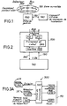
- the automatic location system comprises a management unit 200 connected by a bus 110 to a plurality of detectors 300 and portable equipment 400 intended to be carried by people and / or objects.
- the detectors 300 are distributed in a monitored area 120 such as the building of a company, preferably in different places where people and / or objects to be located circulate in the monitored area.
- the term “monitored area” is understood to mean an area in which the detectors 300 are capable of identifying portable equipment 200 and therefore a person or an object carrying portable equipment.
- the portable equipment is autonomous and communicates with the detectors by exchange of coded signals in the form of modulated waves, for example infrared signals. It will be understood that the communication between a portable equipment and a detector can only be established if the portable equipment is in the vicinity of the detector so that if the communication is established, the position of the portable equipment is given by the position of the known detector of the management unit 200.
- the automatic location system according to the invention is preferably designed to operate in at least three modes, the "presence” mode in which the management unit and the detectors are designed to locate a particular portable device, the "passage” mode in which the management unit and the detectors are designed to locate at the same time a plurality of portable devices without particular distinction and the "manual" mode in which the wearer of portable equipment voluntarily operates his portable equipment to be located by the management unit.
- Presence in which the management unit and the detectors are designed to locate a particular portable device
- the "passage” mode in which the management unit and the detectors are designed to locate at the same time a plurality of portable devices without particular distinction
- the “manual” mode in which the wearer of portable equipment voluntarily operates his portable equipment to be located by the management unit.
- the management unit 200 is connected to a data input unit 140 to receive an input signal 130 corresponding to a command to locate a person or an object in the monitored area 120.
- the management unit 200 comprises a control and calculation unit 220 incorporating means for memorizing adapted data and programs, interface means 230 connected to the control and calculation unit 220 and to the data input unit 140 for translating the location control signal into an instruction recognizable by the control and calculation unit 220, bus interface means 210, 215 for enabling communication by bus with the detectors 300, according to a determined communication protocol, for example the "HDLC" protocol.
- All the hardware constituting the management unit 200, as well as the associated programs, can advantageously consist of a suitably programmed computer.
- the management unit 200 supplies the data input unit 140, which can advantageously be a computer dedicated to an application of any kind, with an output signal corresponding to a localization information of portable equipment 400 as will be described later.
- the connection between the management unit 200 and the data input unit 140 is, for example, of the "V24" type, known per se and easy to implement.
- the communication between the management unit 200 and the detectors 300 is carried out in the form of the exchange of control messages and data compatible with a communication protocol, in this case with the "HDLC" protocol.
- a communication protocol in this case with the "HDLC" protocol.
- the detectors 300 all being connected to bus 110, the communication protocol on bus 110 includes a conventional mechanism for managing message collisions in order to ensure proper communication on the bus as well as a mechanism for monitoring transmission errors. This type of mechanism being well known, it will not be described in more detail below.
- a detector 300 comprises transmission / reception means 310, 320 of the detector, a control unit 330 of the detector connected to the transmission / reception means 310, 320 of the detector, a storage means 340 of detector connected to the detector control unit 330 and interface means 360, 370 connecting the detector control unit 330 to the bus 110.
- the bus 110 is made up of two wired links connecting the bus interfaces 210, 215 of the management unit 200 and the bus interfaces 360, 370 of each detector 300.
- a wired link and its corresponding bus interfaces (215, 360) are dedicated to sending messages from the management unit 200 to the detectors 300.
- the other wired link and its corresponding bus interfaces (210, 370) are dedicated to sending messages from one or more detectors 300 to the management unit 200.
- the bus link between the management unit 200 and the detectors is given to as an example.
- this known type of connection has the advantage of offering the location system according to the invention a very flexible architecture. Thus it is particularly easy to extend the monitored area by increasing the number of detectors connected to the bus 110 without significant modifications to the overall operation of the location system.
- the detectors 300 are designed to operate according to the two modes indicated above, the "presence” mode and the "passage” mode.
- the configuration of a detector 300 determines its operating mode.
- the configuration parameters are loaded into the storage means 340 of the detector at the time of the initialization of the localization system or during its operation in localization.
- the loading of the configuration parameters of the detectors is taken over by the management unit 200 for example in the form of sending configuration messages via the bus 110.
- One of the configuration parameters of a detector is a code individual detector identification such as a logical address, recorded in the detector storage means 340 such as an EEPROM memory.
- each detector 300 is known to the management unit by its individual detector identification code.
- the detector control unit 330 is designed to be sensitive to the reception of a message on the bus interface means 360 corresponding to a location command sent by the data input unit 140.
- This message corresponding to a location command is sent by the management unit 200, intended for all the detectors 300 connected to the bus 110 and configured in "presence” mode.
- This message includes a command part corresponding to the content of the request identifiable by the detector control units 330 and a given part corresponding to the individual identification code of the portable equipment to be located in the monitored area 120. It will thus be understood that Each portable device 400 is assigned an individual identification code as will be described below.
- the control unit 330 of a detector 300 configured in "presence" mode activates the transmission means 310 to generate a first coded signal in the form of modulated waves.
- the information contained in the first coded signal identifies in particular an individual code of a portable device 400.
- This first coded signal is broadcast by all the detectors configured in "presence” mode having received said message corresponding to a location command, each detector 300 diffusing said coded signal in part of the monitored area 110. It will be understood that when the monitored area 110 is a building, the detectors 300 are placed in the rooms of the building and each detector has a broadcasting capacity covering the volume d 'a piece.
- the transmission 310 and reception 320 means each comprise several diodes transmission and reception respectively allowing the transmission and reception of coded signals in the form of modulated waves, such as infrared optical signals.
- the modulation is of the pulse position type in order to allow emissions of high power and of short duration.
- the detectors 300 configured in "presence" mode, each broadcast a first coded signal, for example in the form of light rays modulated in the infrared spectrum (represented by IR in the figure 3), capable of being picked up by portable equipment 400.
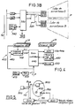
- portable equipment 400 comprises means for transmitting / receiving 410,420 of coded signals in the form of modulated waves, a control means 440, a storage means 430 for storing an identification code individual portable equipment, an alarm means 450 and a current supply means such as a battery 470 coupled with solar cells 475.
- the reception means 410 consists of a reception diode and a high gain amplifier block capable of receiving the first coded signal in the form of modulated waves and supplying the control means 440 with the information carried by this first. signal, an individual identification code for portable equipment.
- the reception means 410 will comprise several reception diodes distributed over the surface of the portable equipment to collect most of the first coded signal broadcast by a detector 300. In this case, good reception of the first coded signal by the receiving means 410 of the portable equipment is practically independent of the relative position of the latter in the diffusion zone of a detector 300.
- the control means 440 is chosen to have a rest mode in which its current consumption is almost zero as well as an activation input ( symbolized by RESET in Figure 4) restoring it to a normal operating mode.
- One such control means 440 may be the RTC PCD3342 microcontroller.
- An activation logic 465 connected to the reception means 410 and to the control means 440 has the function of processing the first pulse of the first coded signal received by the reception means 410 to restore the normal operating mode of the control means 440 by activating its RESET input. Once the control means in the active state, the activation logic 465 directs the following pulses of the first coded signal to an interrupt input (symbolized by INTER in FIG. 4) of the control means 440.
- the means of control 440 is designed to decode the following pulses of the first coded signal so as to recover an individual identification code of portable equipment and compare this code with the individual identification code recorded in the storage means 430.
- the control unit 440 controls the transmission means 420, via a control interface 425, to generate a second coded signal in the form of modulated waves, such as an optical signal modulated in the spectrum infrared, and activate the alarm means 450.
- the transmission means 420 comprises one or more transmission diodes of a modulated optical signal, for example an infrared signal, for di fuse the second coded signal directive or radiant respectively.
- the alarm means 450 is advantageously an audible alarm having the same role as the alarm of portable equipment of the "pager" type. If the detected code and the registered code do not are not identical, the control unit 440 does not generate a second coded signal and locks in the inactive state.
- the second coded signal is capable of being interpreted by a detector as a confirmation of presence in response to the first coded signal transmitted.
- the second coded signal can repeat the individual identification code of the portable equipment 400.
- the second coded signal received by reception means 320 from a detector 300 is supplied to control means 330 of the detector.
- the control means 330 of the detector 300 generates a location message containing the individual identification code of the portable equipment having emitted the second coded signal and its individual detector identification code to supply the message to the management unit 200 via bus 110.
- the location of the person or object carrying the portable equipment which was sensitive to the first coded signal emitted by the detectors is easily obtained by associating the individual identification code of the detector which emitted the location message and the location of said detector in the monitored area. This association can be achieved by software using correspondence tables well known to those skilled in the art.
- the management unit is designed to locate a plurality of portable devices for the purpose of monitoring their movement.
- the "passage” mode also includes an additional functionality allowing to monitor the direction of passage of the carriers of portable equipment.
- the management unit 200 sends a destination control message to all the detectors 300 in which the given part corresponds to a general identification code for portable equipment.
- the detectors 300 In response to this command message, the detectors 300 emit a first coded signal, via their respective detector emission means 310, representative of the general identification code of portable equipment. Each portable equipment sensitive to the first coded signal, transmits in response, via the portable equipment transmission means 420, a second coded signal representative of its own portable equipment identification code as described above.
- the detector 300 having activated the portable equipment 400 and detected the second coded signal, supplies the management unit 200, in the form of a message, its individual detector identification code and the individual identification code d portable equipment activated portable equipment.
- the management unit can maintain a data table in which each identification code of portable equipment is linked to a code of detector identification of the detector that activated the portable equipment in question.
- the detectors 300 are designed to detect the direction of passage of portable equipment.
- FIG 3B there is shown a detector 300 in which the transmission / reception means 310, 320 are divided into two distinct groups A, B.
- the transmit / receive groups 310A, 320A and 310B, 320B are controlled alternately and cyclically by a timing means 335 connected to the control unit 330.
- Each group A, B comprises a plurality of transmit / receive diodes arranged to cover a surveillance area forming a lobe.
- the geometry of a lobe is obtained, in a known manner, by adjusting the intensity of the current supplying the transmission diodes and by orienting the reception diodes suitably.
- the transmission / reception diodes of the two groups A, B define two non-overlapping monitoring lobes A, B formed symmetrically with respect to a passage axis P.
- the detector 300 is designed so that each group of diodes A, B independently detects the presence of portable equipment inside the surveillance zone which it covers.
- the detector storage means 340 also comprises two memory areas for storing two separate detector identification codes (Code A, Code B) assigned respectively to each group A, B of transmission / reception diodes.
- the detector 300 shown in FIG. 3B therefore constitutes a particular type of detector of the location system according to the invention, this particular type of detector finally corresponding to a juxtaposition of two detectors as shown in FIG. 3A.
- the detector control unit 330 of the detector of FIG. 3B activates the timing means 335 so that a first coded signal is alternately and cyclically emitted by the diodes d of each group A, B.
- the detector 300 When the detector 300 detects, by the reception diodes of a group A, B, a second coded signal emitted by a portable equipment in response to the first coded signal, it sends a message to the management unit 200 containing the code identification of the detector assigned to the group of diodes (code A or code B) having detected the second coded signal and the individual identification code of the portable equipment detected by this group.
- the messages generated by the detectors 300 are compiled by the management unit and the direction of passage of localized portable equipment is obtained by statistical processing.
- the purpose of the "manual" mode is to allow the wearer of portable equipment to voluntarily identify himself to the management unit. This operation is more particularly intended to be used in applications of the round security type.
- portable equipment 400 further comprises an operating means 460, for example a switch of the push button type, connected to the activation logic 465.
- the actuation of the operating means 460 forces the logic d activation 465 to activate the RESET input of the control means 440 and to provide the control means 440, on the INTER input, with a manual activation signal.
- the control means 440 restored to normal operating mode, extracts the individual identification code of portable equipment in the storage means 430 and generates a second coded signal via the interface of command 425 which is transmitted in the form of waves modulated by the transmission means 420.
- a detector 300 In “manual" mode, a detector 300, suitably configured, is in the passive state, awaiting reception of a second coded signal.
- the passive state of a detector 300 is signaled to the wearer of the portable equipment 400 by a display means 350, for example an indicator light, connected to the control unit 330 of the detector.
- the detector control unit 330 is arranged to measure the availability state of the bus 110, for example using a program known per se, and to control the display means 350 as a function of the result of the measured.
- the control unit 330 of the detector activates the display means 350 when the bus 110 is available.
- the reception means 320 of the detector are in a state to receive a second coded signal.
- a second coded signal is emitted by a portable equipment 400, in response to the actuation of its operating means 460, this is received by the receiving means 320 of the detector 300 close to the portable equipment 400 in question.
- the information contained in the second coded signal is supplied to the control unit 330 of the detector so that the latter generates a location message comprising the individual identification code of the portable equipment having emitted the second coded signal and its own individual detector identification code.
- This location message is then transmitted to the management unit 200 via the bus 110. Its interpretation by the management unit 200 is carried out in the same manner as described above.
- the individual identification code of portable equipment contains additional information relating to a service. particular, for example an amount of money. It will then be understood that the portable equipment 300 can be used as an electronic purse. It is also possible to provide for the use of the portable equipment 400 for several services by means of switches connected to the control means 440 of portable equipment to control its operation as a function of the service chosen.
- the storage means 430 of portable equipment consists of an EEPROM memory arranged on a removable card, of the smart card type, capable of being able to be personalized. Furthermore, the EEPROM memory is subdivided into memory blocks each identifiable by an address in which micro-coded instructions are recorded for controlling the micro-controller 440 as a function of the type of the first coded signal detected by the equipment reception means 410 portable (specific code for identifying portable equipment or general code for identifying portable equipment).
- the current supply means consist of a battery 470 permanently recharged by solar cells 475 to give the portable equipment a great autonomy.
- This autonomy is further increased in particular by the use of a microcontroller 440 having a rest mode, a memory 430 with low energy consumption and an activation logic 465 energizing the microcontroller only when the portable equipment is requested, that is to say when a first coded signal is received by the reception means 410 or when the operating means 460 is actuated.
- a private installation telephone switching system consists of a network head 600 designed to direct telephone calls to at least one of a plurality of telephone stations.
- a detector 300 is associated with a telephone station 500 and with the individual identification code of the detector 300 considered the call number of the associated telephone station 500.
- the individual identification code of a portable device 400 is associated with the extension number of the person to whom the portable device is assigned.
- the head of the network 600 is coupled to the management unit 200 and is arranged to provide the management unit with a location control signal in the event that a telephone call can not be made because only the person to whom the call is intended is far from its assigned telephone extension.
- the management unit 200 transmits to the detectors 300 a message corresponding to the location command.
- This message includes the individual identification code of the portable equipment 400 carried by the person to whom the call is intended.
- the individual identification code in this case corresponds to the extension number of the person called.
- the detectors 300 then emit a first coded signal containing this individual identification code of portable equipment according to the procedure described above with reference to the "presence" mode.
- Portable equipment 400 whose individual identification code is identical to the individual portable equipment identification code sought, emits a second coded signal.
- This second coded signal is received by the detector 300 closest to the person called.
- This detector transmits a location message to the management unit.
- the location message includes the number of the associated telephone set 500 as the individual detector identification code.
- the management unit 200 then supplies the head of the telephone network 600 with a signal corresponding to the number of the telephone set associated with the detector 300 having received the second coded signal. It then suffices for the network head 600 to direct the waiting telephone call to the telephone station 500 which has just been located.
- a second use of the location system according to the invention relates to access control procedures in a computer network.
- the location system according to the invention makes it possible to increase the security of a computer network.
- a computer network generally consists of a plurality of data entry stations, for example terminals, linked to a central computer. Access to the central computer is subject to knowledge of access codes authorizing a connection for an authorized person. An unauthorized person can, however, enter the computer network by knowing the access codes.
- the persons authorized to enter the computer network are provided with portable equipment and each data entry station is associated with a detector.
- the central computer is connected to the management unit of the location system.
- the central computer When a request for connection to the computer network is made by a person via a data entry station, the central computer recognizes the access codes required for the connection. In response to access codes, the central computer transmits to the management unit a signal for the location of the portable equipment assigned to the person responding to these access codes.
- the management unit then transmits to the detectors a message corresponding to the location control of the portable equipment, the individual identification code of which corresponds to the person identified by the access codes.
- the management unit supplies the central computer with the individual identification code of the detector having received a second coded signal.
- the central computer can then, by correspondence, identify the data entry station associated with the detector having received the second coded signal and decide to establish the connection if this data entry station is the one which emitted the codes. 'access.
Landscapes
- Physics & Mathematics (AREA)
- General Physics & Mathematics (AREA)
- Engineering & Computer Science (AREA)
- Computer Networks & Wireless Communication (AREA)
- Electromagnetism (AREA)
- Mobile Radio Communication Systems (AREA)
- Alarm Systems (AREA)
- Emergency Alarm Devices (AREA)
- Burglar Alarm Systems (AREA)
- Radar Systems Or Details Thereof (AREA)
Claims (6)
- System zur Lokalisierung von Personen und/oder Gegenständen in einem überwachten Bereich (120), das eine Verwaltungseinheit für den Empfang von Lokalisierungsbefehlen, eine Vielzahl von Detektoren (300), Lokalisierungssignalsender, die mit der Verwaltungseinheit verbunden und im überwachten Bereich verteilt sind, und mindestens eine Sende-Empfangseinrichtung (400) aufweist, die eine zu lokalisierenden Person trägt und/oder sich bei einem zu lokalisierenden Gegenstand befindet, wobei jeder mit einer Steuereinheit (330) versehene Detektor Mittel (310, 320) zur Aussendung und zum Empfang von Infrarotsignalen mit Impulskodemodulation aufweist, die von der Verwaltungseinheit gesteuert werden, und wobei jede Sende-Empfangseinrichtung außerdem eine Steuereinheit (440) und Mittel (410, 420) zum Senden und Empfangen von Infrarotsignalen mit Impulskodemodulation aufweist, dadurch gekennzeichnet, daß jede tragbare Sende-Empfangseinheit (400) ein Speichermittel besitzt, das einen individuellen Identifizierungskode enthält, der von dieser Einheit verarbeitet wird, um ein kodiertes Infrarotsignal zur Lokalisierung bei Empfang eines ersten kodierten Signalisations-Infrarotsignals zu senden, das einen Identifikationskode enthält, der dem des betroffenen Geräts entspricht, und ein Detektor überträgt bei Empfang eines von einem Gerät kommenden kodierten Lokalisierungs-Infrarotsignals einen ihm eigenen Identifikationskode zusammen mit dem Identifikationskode dieses Geräts.
- Lokalisierungssystem nach Anspruch 1, dadurch gekennzeichnet, daß mindestens einer der Detektoren, die für eine Durchgangs-Überwachung bestimmt sind, zwei unterschiedliche Gruppen von Sende- und Empfangsmitteln (310, 320) enthält, die je in einem eigenen Überwachungsbereich aktiv sind, wobei die beiden Gruppen abwechselnd von einem zyklischen Taktmittel (335) gesteuert werden und mit voneinander unterschiedlichen Identifikationskodes versehen sind, um die Durchgangsrichtung eines tragbaren Geräts von einem Bereich in den anderen zu erfassen.
- Lokalisierungssystem nach Anspruch 1, dadurch gekennzeichnet, daß mindestens ein tragbares Gerät ein Betätigungsmittel (460) aufweist, das mit seiner Steuereinheit (440) verbunden ist, um bei einer gewollten Identifikation und gemäß einem manuellen Modus die Aussendung eines zweiten kodierten Lokalisierungs-Infrarotsignals auszulösen, das vom individuellen Identifikationskode des betroffenen Geräts abhängt.
- Lokalisierungssystem nach Anspruch 1, dadurch gekennzeichnet, daß mindestens ein tragbares Gerät ein Alarmmittel (450) aufweist, das mit seiner Steuereinheit (440) verbunden ist und beim Aussenden eines zweiten kodierten Lokalisierungs-Infrarotsignal durch das Gerät aktiviert wird.
- Lokalisierungssystem nach Anspruch 4, bei dem die Detektoren mit der Verwaltungseinheit (200) über eine Bus (110) verbunden sind und bei dem mindestens ein Detektor ein Anzeigemittel (350) aufweist, das seinen aktiven oder passiven Zustand anzeigt und das zu diesem Zweck mit der Steuereinheit (330) dieses Detektors verbunden ist, wobei diese Steuereinheit die Verfügbarkeit der Busleitung messen und das Anzeigemittel in Abhängigkeit von dieser Verfügbarkeitsmessung nach Empfang eines kodierten Lokalisierungs-Infrarotsignals durch das Gerät steuern kann, wenn die Sende- und Empfangsmittel (310, 320) des Detektors bei Empfang eines zweiten kodierten Lokalisierungssignals aktiviert wurden, das den Übergang des Detektors in den aktiven Zustand bewirkt.
- Lokalisierungssystem nach einem der Ansprüche 1 bis 5, das einem Informatiknetz zugeordnet ist, um einer berechtigten Person über eine Dateneingabestation Zugang zum Netz zu erlauben, dadurch gekennzeichnet, daß ein individuelles tragbares Gerät (400) dieser Person zugeordnet ist und daß der Zugang zu einer Station durch eine Person von der Lokalisierung eines geeigneten tragbaren Geräts durch einen in der Nähe der Station befindlichen Detektor (300) abhängig ist.
Applications Claiming Priority (2)
| Application Number | Priority Date | Filing Date | Title |
|---|---|---|---|
| FR9014524A FR2669454B1 (fr) | 1990-11-21 | 1990-11-21 | Systeme de localisation de personnes et/ou d'objets dans une zone surveillee. |
| FR9014524 | 1990-11-21 |
Publications (2)
| Publication Number | Publication Date |
|---|---|
| EP0487420A1 EP0487420A1 (de) | 1992-05-27 |
| EP0487420B1 true EP0487420B1 (de) | 1997-11-05 |
Family
ID=9402433
Family Applications (1)
| Application Number | Title | Priority Date | Filing Date |
|---|---|---|---|
| EP91403142A Expired - Lifetime EP0487420B1 (de) | 1990-11-21 | 1991-11-21 | Personen- und/oder Objektlokalisierungssystem in einer überwachten Zone |
Country Status (5)
| Country | Link |
|---|---|
| EP (1) | EP0487420B1 (de) |
| AT (1) | ATE160041T1 (de) |
| DE (1) | DE69128126T2 (de) |
| ES (1) | ES2110434T3 (de) |
| FR (1) | FR2669454B1 (de) |
Families Citing this family (3)
| Publication number | Priority date | Publication date | Assignee | Title |
|---|---|---|---|---|
| DE9317993U1 (de) * | 1993-11-09 | 1994-03-31 | Lillig, Heiner, 45663 Recklinghausen | Vorrichtung zum ortsaufgelösten Erfassen eines Rufsignals, insbesondere eines Patientenrufes in Krankenhäusern, Kliniken u.dgl. |
| DE19812909A1 (de) * | 1998-03-18 | 1999-10-14 | Bb Data Inf & Komm Syst Gmbh | Inventarisierungssystem bei dem eine Lokalisierungskennung aus einem Energienetz bezogen wird |
| US6236858B1 (en) * | 1998-06-30 | 2001-05-22 | Avaya Technology Corp. | Wireless terminal automatically alerting user upon wireless terminal entering a specified physical location |
Family Cites Families (5)
| Publication number | Priority date | Publication date | Assignee | Title |
|---|---|---|---|---|
| US3696384A (en) * | 1971-07-08 | 1972-10-03 | Recognition Devices | Ultrasonic tracking and locating system |
| WO1982000377A1 (en) * | 1980-07-21 | 1982-02-04 | Taylor D | A location device |
| US4598275A (en) * | 1983-05-09 | 1986-07-01 | Marc Industries Incorporated | Movement monitor |
| GB2193359B (en) * | 1986-07-31 | 1990-07-11 | Multitone Electronics Plc | Area communications systems |
| GB2216358A (en) * | 1988-02-26 | 1989-10-04 | Siemens Ag | Tracking moving object |
-
1990
- 1990-11-21 FR FR9014524A patent/FR2669454B1/fr not_active Expired - Fee Related
-
1991
- 1991-11-21 EP EP91403142A patent/EP0487420B1/de not_active Expired - Lifetime
- 1991-11-21 AT AT91403142T patent/ATE160041T1/de not_active IP Right Cessation
- 1991-11-21 DE DE69128126T patent/DE69128126T2/de not_active Expired - Fee Related
- 1991-11-21 ES ES91403142T patent/ES2110434T3/es not_active Expired - Lifetime
Also Published As
| Publication number | Publication date |
|---|---|
| DE69128126D1 (de) | 1997-12-11 |
| DE69128126T2 (de) | 1998-03-05 |
| EP0487420A1 (de) | 1992-05-27 |
| FR2669454B1 (fr) | 1995-06-02 |
| ES2110434T3 (es) | 1998-02-16 |
| FR2669454A1 (fr) | 1992-05-22 |
| ATE160041T1 (de) | 1997-11-15 |
Similar Documents
| Publication | Publication Date | Title |
|---|---|---|
| EP0722157B1 (de) | System zur Sicherung von Gegenständen gegen Diebstahl | |
| EP2082252B1 (de) | Schutz-, sicherheits- und verlagerungsverfolgungs-leucht-plakettensystem | |
| FR2690265A1 (fr) | Système de surveillance d'un objet meuble ou mobile. | |
| CN101194275B (zh) | 光学识别芯片 | |
| CA2131726A1 (en) | Tracking and/or identification system | |
| FR2949268A1 (fr) | Dispositif de detection d'entree et de reconnaissance de badges transpondeurs, systeme de surveillance le comprenant et procede de surveillance mis en oeuvre par ledit systeme | |
| FR2665038A1 (fr) | Systeme de radio-identification a badges repondeurs, unites constitutives d'un tel systeme et agencement exploitant correspondant. | |
| WO2015004226A1 (fr) | Dispositif et procédé de contrôle d'accès à au moins une machine | |
| FR2643726A1 (fr) | Systeme d'identification sans contact d'un mobile en deplacement a proximite d'un poste fixe | |
| CA2413530A1 (fr) | Ensemble permettant de lire automatiquement une information et systeme de controle ou de suivi a distance comportant au moins un tel ensemble | |
| EP0487420A1 (de) | Personen- und/oder Objektlokalisierungssystem in einer überwachten Zone | |
| WO1992009054A1 (fr) | Dispositif d'information sur un article et systeme informatique l'utilisant | |
| EP1153369B1 (de) | Verfahren zur detektion von tragbaren objekten und durchführungsystem | |
| FR2814267A1 (fr) | Procede de mise en oeuvre et dispositif de surveillance destine a prevenir lors d'une intrusion dans la zone qu'il surveille | |
| EP0639486B1 (de) | Alarmsystem für eine mobile Funkstation | |
| EP0678838B1 (de) | Überwachungssystem von Personen an einem Ort | |
| FR2673743A1 (fr) | Procede et dispositif de controle de presence d'individus dans un site. | |
| FR3108432A1 (fr) | Système et procédé de détection de personnes. | |
| FR2741178A1 (fr) | Installation de protection contre le vol pour des vehicules automobiles | |
| EP1057355B1 (de) | Vorrichtung und verfahren zum nachweis der anwesenheit eines sich in betrieb befindlichen zellularen gsm-telefons oder jeglicher anderen mobilen geräte | |
| FR2720178A1 (fr) | Ensemble de protection d'appareils, en particulier contre le vol, sous-ensemble de détection et sous-ensemble de surveillance pour un tel ensemble de protection. | |
| FR2888940A1 (fr) | Systeme de localisation par utilisation combinee de mesures de pression atmospherique et d'analyse de reception d'ondes electromagnetiques | |
| FR2946778A1 (fr) | Dispositif d'appel de differentes categories de personnes | |
| WO2023079446A1 (fr) | Dispositif et procédé d'avertissement pour défibrillateur | |
| WO2003066392A1 (fr) | Module de communication de donnees d'alarme et systeme d'alarme le comportant |
Legal Events
| Date | Code | Title | Description |
|---|---|---|---|
| PUAI | Public reference made under article 153(3) epc to a published international application that has entered the european phase |
Free format text: ORIGINAL CODE: 0009012 |
|
| AK | Designated contracting states |
Kind code of ref document: A1 Designated state(s): AT BE CH DE DK ES FR GB IT LI NL SE |
|
| 17P | Request for examination filed |
Effective date: 19921124 |
|
| 17Q | First examination report despatched |
Effective date: 19950529 |
|
| GRAG | Despatch of communication of intention to grant |
Free format text: ORIGINAL CODE: EPIDOS AGRA |
|
| GRAH | Despatch of communication of intention to grant a patent |
Free format text: ORIGINAL CODE: EPIDOS IGRA |
|
| GRAH | Despatch of communication of intention to grant a patent |
Free format text: ORIGINAL CODE: EPIDOS IGRA |
|
| GRAA | (expected) grant |
Free format text: ORIGINAL CODE: 0009210 |
|
| AK | Designated contracting states |
Kind code of ref document: B1 Designated state(s): AT BE CH DE DK ES FR GB IT LI NL SE |
|
| PG25 | Lapsed in a contracting state [announced via postgrant information from national office to epo] |
Ref country code: NL Free format text: LAPSE BECAUSE OF FAILURE TO SUBMIT A TRANSLATION OF THE DESCRIPTION OR TO PAY THE FEE WITHIN THE PRESCRIBED TIME-LIMIT Effective date: 19971105 Ref country code: DK Free format text: LAPSE BECAUSE OF NON-PAYMENT OF DUE FEES Effective date: 19971105 |
|
| REF | Corresponds to: |
Ref document number: 160041 Country of ref document: AT Date of ref document: 19971115 Kind code of ref document: T |
|
| REG | Reference to a national code |
Ref country code: CH Ref legal event code: EP |
|
| GBT | Gb: translation of ep patent filed (gb section 77(6)(a)/1977) |
Effective date: 19971106 |
|
| REF | Corresponds to: |
Ref document number: 69128126 Country of ref document: DE Date of ref document: 19971211 |
|
| ITF | It: translation for a ep patent filed | ||
| REG | Reference to a national code |
Ref country code: CH Ref legal event code: NV Representative=s name: GEC ALSTHOM SALES NETWORK SA |
|
| REG | Reference to a national code |
Ref country code: ES Ref legal event code: FG2A Ref document number: 2110434 Country of ref document: ES Kind code of ref document: T3 |
|
| NLV1 | Nl: lapsed or annulled due to failure to fulfill the requirements of art. 29p and 29m of the patents act | ||
| PLBE | No opposition filed within time limit |
Free format text: ORIGINAL CODE: 0009261 |
|
| STAA | Information on the status of an ep patent application or granted ep patent |
Free format text: STATUS: NO OPPOSITION FILED WITHIN TIME LIMIT |
|
| 26N | No opposition filed | ||
| PGFP | Annual fee paid to national office [announced via postgrant information from national office to epo] |
Ref country code: GB Payment date: 20011012 Year of fee payment: 11 |
|
| PGFP | Annual fee paid to national office [announced via postgrant information from national office to epo] |
Ref country code: CH Payment date: 20011016 Year of fee payment: 11 |
|
| PGFP | Annual fee paid to national office [announced via postgrant information from national office to epo] |
Ref country code: AT Payment date: 20011026 Year of fee payment: 11 |
|
| PGFP | Annual fee paid to national office [announced via postgrant information from national office to epo] |
Ref country code: DE Payment date: 20011031 Year of fee payment: 11 |
|
| PGFP | Annual fee paid to national office [announced via postgrant information from national office to epo] |
Ref country code: SE Payment date: 20011105 Year of fee payment: 11 |
|
| PGFP | Annual fee paid to national office [announced via postgrant information from national office to epo] |
Ref country code: FR Payment date: 20011106 Year of fee payment: 11 |
|
| PGFP | Annual fee paid to national office [announced via postgrant information from national office to epo] |
Ref country code: BE Payment date: 20011114 Year of fee payment: 11 |
|
| PGFP | Annual fee paid to national office [announced via postgrant information from national office to epo] |
Ref country code: ES Payment date: 20011119 Year of fee payment: 11 |
|
| REG | Reference to a national code |
Ref country code: GB Ref legal event code: IF02 |
|
| PG25 | Lapsed in a contracting state [announced via postgrant information from national office to epo] |
Ref country code: GB Free format text: LAPSE BECAUSE OF NON-PAYMENT OF DUE FEES Effective date: 20021121 Ref country code: AT Free format text: LAPSE BECAUSE OF NON-PAYMENT OF DUE FEES Effective date: 20021121 |
|
| PG25 | Lapsed in a contracting state [announced via postgrant information from national office to epo] |
Ref country code: SE Free format text: LAPSE BECAUSE OF NON-PAYMENT OF DUE FEES Effective date: 20021122 Ref country code: ES Free format text: LAPSE BECAUSE OF NON-PAYMENT OF DUE FEES Effective date: 20021122 |
|
| PG25 | Lapsed in a contracting state [announced via postgrant information from national office to epo] |
Ref country code: LI Free format text: LAPSE BECAUSE OF NON-PAYMENT OF DUE FEES Effective date: 20021130 Ref country code: CH Free format text: LAPSE BECAUSE OF NON-PAYMENT OF DUE FEES Effective date: 20021130 Ref country code: BE Free format text: LAPSE BECAUSE OF NON-PAYMENT OF DUE FEES Effective date: 20021130 |
|
| BERE | Be: lapsed |
Owner name: *ALCATEL BUSINESS SYSTEMS Effective date: 20021130 |
|
| PG25 | Lapsed in a contracting state [announced via postgrant information from national office to epo] |
Ref country code: DE Free format text: LAPSE BECAUSE OF NON-PAYMENT OF DUE FEES Effective date: 20030603 |
|
| EUG | Se: european patent has lapsed | ||
| GBPC | Gb: european patent ceased through non-payment of renewal fee | ||
| REG | Reference to a national code |
Ref country code: CH Ref legal event code: PL |
|
| PG25 | Lapsed in a contracting state [announced via postgrant information from national office to epo] |
Ref country code: FR Free format text: LAPSE BECAUSE OF NON-PAYMENT OF DUE FEES Effective date: 20030731 |
|
| REG | Reference to a national code |
Ref country code: FR Ref legal event code: ST |
|
| REG | Reference to a national code |
Ref country code: ES Ref legal event code: FD2A Effective date: 20031213 |
|
| PG25 | Lapsed in a contracting state [announced via postgrant information from national office to epo] |
Ref country code: IT Free format text: LAPSE BECAUSE OF NON-PAYMENT OF DUE FEES Effective date: 20051121 |