EP0487450A2 - Procédés et dispositifs de mesure de force à fibre optique - Google Patents
Procédés et dispositifs de mesure de force à fibre optique Download PDFInfo
- Publication number
- EP0487450A2 EP0487450A2 EP91810862A EP91810862A EP0487450A2 EP 0487450 A2 EP0487450 A2 EP 0487450A2 EP 91810862 A EP91810862 A EP 91810862A EP 91810862 A EP91810862 A EP 91810862A EP 0487450 A2 EP0487450 A2 EP 0487450A2
- Authority
- EP
- European Patent Office
- Prior art keywords
- optical waveguide
- force
- measurement
- light
- light waves
- Prior art date
- Legal status (The legal status is an assumption and is not a legal conclusion. Google has not performed a legal analysis and makes no representation as to the accuracy of the status listed.)
- Granted
Links
Images


Classifications
-
- G—PHYSICS
- G01—MEASURING; TESTING
- G01L—MEASURING FORCE, STRESS, TORQUE, WORK, MECHANICAL POWER, MECHANICAL EFFICIENCY, OR FLUID PRESSURE
- G01L1/00—Measuring force or stress, in general
- G01L1/24—Measuring force or stress, in general by measuring variations of optical properties of material when it is stressed, e.g. by photoelastic stress analysis using infrared, visible light, ultraviolet
- G01L1/242—Measuring force or stress, in general by measuring variations of optical properties of material when it is stressed, e.g. by photoelastic stress analysis using infrared, visible light, ultraviolet the material being an optical fibre
- G01L1/243—Measuring force or stress, in general by measuring variations of optical properties of material when it is stressed, e.g. by photoelastic stress analysis using infrared, visible light, ultraviolet the material being an optical fibre using means for applying force perpendicular to the fibre axis
Definitions
- the invention relates to a method for fiber optic force measurement, which is based on the voltage-induced birefringence change of a single-mode optical waveguide.
- the subject matter of the invention is also a device for fiber optic measurement of the absolute value of the prestress in a mechanical component that is highly stressed by tensile or compressive forces.
- An indirect one is usually used to determine the preload Method applied, namely the measurement via the torque.
- a torque check of an expansion screw 1 and a re-expansion of the expansion elements 2 can remedy the situation.
- undefined friction influences static, sliding friction
- the torque is also not a clear function of the preload and can only be measured when tightening, i.e. when the anchor D is set.
- a force sensor must be integrated into the component, for example the dowel.
- force sensors are piezoelectric systems (quartz force rings) and systems with strain gauges (DSM) z. B. in the form of load cells or as an annular force transducer.
- DSM strain gauges
- Such direct measuring instruments for determining the pretension generally have, apart from the high price, the disadvantage of being too large in design for many applications.
- the quartz sensor is also only suitable for dynamic measurements.
- Indirect methods are also known, e.g. B. based on the change in length of the prestressed threaded rod of the anchor, the z. B. can be detected with ultrasound time measurement.
- this method requires that the dowel itself be calibrated and its data registered.
- the invention is therefore based on the object of developing a measuring method and a comparatively inexpensive force sensor which can be used for the continuous or need-based measurement of the absolute value of the in a highly stressed state mechanical component occurring forces.
- the invention proposes two basic methods or force measuring devices.
- the one is based on the type of force measurement described in the literature references mentioned, but with the essential addition according to the invention that two wavelengths are used simultaneously or sequentially in order to eliminate the modulo 2 ⁇ uncertainty therefrom, as explained in detail below .
- the second method variant proposed according to the invention is a compensation method in which the phase or path difference of the two linear modes caused by the birefringence in the optical fiber is compensated for by a Michelson interferometer.
- a light source that is as incoherent as possible, ie not a monochromatic light source, such as a laser diode, is used and the so-called coherence detection is used for signal evaluation.
- the inventive method of the type mentioned at the outset for fiber-optic force measurement is according to the first of the invention Solution variant characterized in that in order to achieve clear measurement results, i.e. for absolute measurement, two light waves of different wavelengths are radiated into one end of the optical waveguide, and the phase difference between the two linear modes at the other end of the line caused by the force acting on the optical waveguide and the resulting change in birefringence Optical fiber emerging light waves detected and evaluated as a measure of the force.
- a device for fiber-optic measurement of the absolute value of the prestress in a mechanical component that is highly stressed by tensile or compressive forces, in which the method is used in the defined manner, is characterized according to the invention in that the fiber-optic optical fiber extends over a partial area between its free ends Length is embedded in a pressure-transmitting disc arranged transversely to the direction of force, that one end of the optical fiber - simultaneously or sequentially alternately - is acted upon by two monochromatic light sources of different wavelengths and that the two light waves emerging at the other end of the optical waveguide are passed into the two via a polarizing beam splitter Modes separated, photoelectrically recorded and the preload force in the component is determined by means of a calibrated evaluation logic with intermediate storage of the individual measured values by phase comparison.
- the other method according to the invention namely the so-called compensation method for fiber-optic force measurement, which is based on the voltage-induced birefringence change of a single-mode optical waveguide, is characterized according to the invention in that polarized white light is radiated into one end of the optical waveguide in order to achieve clear measurement results, i.e.
- a Michelson interferometer provided with an upstream polarizing beam splitter for mode separation and at the outputs thereof with ⁇ / 4 plates and an electronically adjustable mirror arrangement , and that the control signal causing the mirror adjustment to compensate for the gear or phase difference is evaluated as a measure of the force.
- FIG. 1 shows a dowel D inserted into a masonry 6, which can be tightened to its screw head by means of a tightening torque Mt, the expanding claws 2 being pressed outwards into the masonry 6 in a known manner via the thread 1, so that The pretensioning force N is generated in the dowel and is transmitted via a washer 3 to a component 17 to be fastened or to the masonry 6.
- an optical fiber 4 that is to say the optical fiber
- the washer 3 Since the FO 4 alone the typical biasing forces of z. B. 10 to 30 kN, distributed over a grinding length of the clamped portion 4 'of 60 mm, the washer 3 must be modified so that the fiber optic cable 4 only has to endure the corresponding fraction of the area and on the other hand by the jacket against overload and corrosion is protected.
- Various methods are suitable for this embedding, e.g. B.
- the embedding must be elastic, ie it must not show any creep or hysteresis behavior, it must be homogeneous and the moduli of elasticity of the embedding material or materials used and their constants must be adapted to the thermal expansion coefficient of the FO 4 and the metal material of the washer 3 described in more detail below be.
- Glass solder of glass types 8472 and 8474 from SCHOTT has proven to be a suitable material as well as Erosil-filled polymethacrylate (cold-curing, heat-curing or UV-curing) from Ivoclar (designations Isopast®, SR-Isosit®, Heliomolar®).
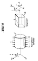
- Fig. 3 illustrates the structural design of a washer 3, which consists of two individual washers 3a and 3b made of metal, between which the portion 4 'of the FO 4 is embedded in a glass solder 5.
- Two spacer rings 6a and 6b are provided for further protection against overload.
- the preload force N which acts between the two ring disks 3a, 3b, causes, among other things, two different tension components in the center of the optical fiber of the FO 4, namely one parallel and the other perpendicular to the pressure on the fiber.
- the elasto-optical properties of the optical fiber 4 create a birefringent medium, i. H. there is a phase shift between the light parallel to the pressure and the polarized perpendicular to it, which passes through the fiber 4. This phase shift is a direct measure of the force acting on the washer 3.
- the phase shift is generally a multiple of 2 ⁇ .
- the preload force N can therefore be determined by simply counting the periodic change in polarization during a loading process. This method fails in subsequent measurements of the prestress because the evaluable result of the stress-induced birefringence is ambiguously modulo 2 ⁇ . This difficulty can be avoided by measuring the phase shift of two light beams with two different wavelengths according to the invention. By comparing the two measurement results, the number of 2 ⁇ periods can be clearly determined in a given measurement range.
- Fig. 4 shows a first exemplary embodiment of the basic structure of a device for carrying out the (first) two-length measuring method according to the so-called quadrature method.
- monochromatic light with two different wavelengths ⁇ 1 and ⁇ 2 in the fiber optic force sensor, as described above.
- the right-hand free end of the FO 4 emits the light to a detector unit 7 for analyzing the polarization of the originally linearly polarized light after passing through the birefringent, embedded portion 4 'of the FO 4.
- the light source consists essentially of two single-mode infrared -Laser diodes LD1 or LD2, the light with wavelengths around 800nm deliver with a wavelength difference of about 10nm, depending on the desired absolute force measuring range.
- both the temperature and the forward current of the laser diodes LD 1, LD 2 should be regulated.
- electronics not shown
- a simple collimator structure with beam splitter ST1 illustrated by two indicated lenses, is sufficient to define polarized light, in particular at a 45 ° tilt to the optical axis, i. H. the voltage axis of the birefringent component to be coupled into the single-mode FO 4 of the force sensor.
- the detector unit 7 comprises a second beam splitter ST2 for separating the two modes.
- One output of the second beam splitter ST2 is followed by a ⁇ / 4 plate 8 and a polarizer P2 before the intensity component (which is a mode) arrives at a first photodetector PD 1.
- the second output of the second beam splitter ST2 acts on a further ⁇ / 4 plate 8 'and a further polarizer P1 a second photodetector PD2.
- the detector unit 7 which is suitable for force measurement with the phase shift method, the detector unit 7 'corresponds to a modified Michelson interferometer.
- ⁇ / 4 plates 11, 12 are interposed between the polarizing beam splitter PST and the mirrors 9, 10.
- the output of the interferometer acts on a further ⁇ / 4 plate 13 and a further polarizer 14, a photodetector, for. B. a photodiode PD.
- One mirror 10 can be displaced perpendicularly to its mirror surface by predeterminable path elements corresponding to a specific phase shift by means of a piezo actuating element 15, the actuating signals of which are predetermined by a control unit 16 implemented, for example, by means of a microprocessor.
- the preload force can be determined on the one hand by the quadrature method (see Ref. [1] and [4]) or by means of the phase step method (Ref. [5]).
- the light that leaves the optical waveguide 4 and arrives at the detector unit 7 is divided into two light beams of the same intensity by the beam splitter ST2. Both then pass through one of the ⁇ / 4 plates 8 and 8 'and one of the polarizers P2 and P1.
- the position of the ⁇ / 4 plates 8, 8 'and the polarizers P1, P2 is now chosen so that the first diode PD1 is a cosine phase shift signal detected and the other PD2 a sinusoidal.
- phase step method (cf. Ref. [5]) was found, which provides good values for the phase shift even with non-ideal components.
- I a (1 + m cos ⁇ ) with a mean intensity and m the degree of modulation.
- at least three independent measurement signals are required. It is, as shown in Fig. 5, cheaper to work with a single photodiode PD, but in addition to use a phase shift unit consisting of the mirror connected to the piezo actuator 15, so that independent measurement signals can be obtained.
- the desired phase shift between these beams can be realized.
- a microprocessor 16 for specifying the electrical signals for positioning the mirror 10 and for further processing the digitized diode signals is advantageous.
- the second basic measuring principle according to the invention is based on the compensation method already mentioned .
- FIG. 6 schematically illustrates the principle of this measurement method, reference being made simultaneously to FIG. 10 with regard to the specific measurement setup.
- Non-coherent light from a light source LQ passes through an input-side polarizer POE and then arrives at the monomodal FO 4, the two main components of the light in the FO 4 in the area of the fiber optic force sensor having a length L (corresponding to 4 ′ ) are influenced differently.
- the phase or path difference induced by the force F is canceled by an electronically controlled compensator 20; H. compensated.
- the control signal required for this in the compensator 20 is a direct measure of the acting force.
- the phase shift unit already explained with reference to FIG. 5 can serve as a compensator; H.
- a modified Michelson interferometer consisting of a polarizing beam splitter PST, which separates the two differently polarized light waves, and two ⁇ / 4 plates 11, 12, which after two passes (reflection at mirrors 9 and 10) change the direction of polarization by 90 ° rotate so that both partial beams overlap in the polarizer POL and act on the photodiode PD.
- the path difference is compensated for by means of the microprocessor control 16 via the mirror 10 attached to the piezo actuator 15.
- ⁇ FO (F) 2 ⁇ ⁇ L ⁇ n (F)
- q denotes a coherence function that depends on the path difference (phase difference) of the two light waves of different polarization. The following applies:
- FIG. 7 and 8 show calculated curves for the intensity curve when using an LED (FIG. 7) on the one hand and a halogen lamp (FIG. 8) on the other hand, the respective spectrum of the light sources with their coherence lengths (LED 8 ⁇ m; halogen lamp 1.5 ⁇ m) and the spectral sensitivity of the photodiode PD were taken into account.
- the photodiode signal is plotted in normalized units against the displacement of the mirror 10.
- the envelope of the "decaying" oscillations depends on the spectral width ⁇ and the coherence length l koh of the respective light source.
- the piezo adjusting element 15 - the force caused by the force in the loaded component, i. H. Phase shift induced in FO 4 canceled (compensated).
- the control signal required for this is therefore a direct measure of the force acting.
- FIG. 9 shows an actual measurement curve when using halogen light as the non-coherent light source LQ (white light source). Similar to the calculated curves according to FIGS. 7 and 8, the minimum is clearly pronounced, although the real measured curve is due to the non-ideal components an incomplete modulation can be seen.
- the phase step method described above and the compensation method explained last are approximately equivalent.
- the compensation method has the decisive advantage that no monochromatic light sources are required, but rather that a simple white light source, for example a light-emitting diode (LED) or a low-voltage halogen lamp, can be used.
- a simple white light source for example a light-emitting diode (LED) or a low-voltage halogen lamp
Landscapes
- Physics & Mathematics (AREA)
- General Physics & Mathematics (AREA)
- Length Measuring Devices By Optical Means (AREA)
- Investigating Or Analysing Materials By Optical Means (AREA)
Applications Claiming Priority (2)
| Application Number | Priority Date | Filing Date | Title |
|---|---|---|---|
| DE4037077A DE4037077A1 (de) | 1990-11-22 | 1990-11-22 | Verfahren und einrichtung zur faseroptischen kraftmessung |
| DE4037077 | 1990-11-22 |
Publications (3)
| Publication Number | Publication Date |
|---|---|
| EP0487450A2 true EP0487450A2 (fr) | 1992-05-27 |
| EP0487450A3 EP0487450A3 (en) | 1993-02-10 |
| EP0487450B1 EP0487450B1 (fr) | 1995-09-20 |
Family
ID=6418679
Family Applications (1)
| Application Number | Title | Priority Date | Filing Date |
|---|---|---|---|
| EP91810862A Expired - Lifetime EP0487450B1 (fr) | 1990-11-22 | 1991-11-07 | Procédés et dispositifs de mesure de force à fibre optique |
Country Status (3)
| Country | Link |
|---|---|
| US (1) | US5308973A (fr) |
| EP (1) | EP0487450B1 (fr) |
| DE (2) | DE4037077A1 (fr) |
Cited By (2)
| Publication number | Priority date | Publication date | Assignee | Title |
|---|---|---|---|---|
| FR2993656A1 (fr) * | 2012-07-23 | 2014-01-24 | Lasstec | Dispositif de mesure peripherique de contrainte |
| EP3502629A1 (fr) * | 2017-12-20 | 2019-06-26 | Innogy SE | Système et procédé de surveillance de la pression d'appui d'une liaison par complémentarité de force et / ou de forme |
Families Citing this family (41)
| Publication number | Priority date | Publication date | Assignee | Title |
|---|---|---|---|---|
| FR2684441A1 (fr) * | 1991-12-02 | 1993-06-04 | Siderurgie Fse Inst Rech | Rouleau mesureur de planeite d'une bande fabriquee en continu. |
| DE4202185A1 (de) | 1992-01-28 | 1993-07-29 | Hilti Ag | Verfahren zur faseroptischen kraftmessung |
| FR2742227B1 (fr) * | 1995-12-07 | 1998-01-09 | Alcatel Contracting Sa | Procede de traitement d'un signal interferometrique pour la mesure d'une force |
| US5892860A (en) * | 1997-01-21 | 1999-04-06 | Cidra Corporation | Multi-parameter fiber optic sensor for use in harsh environments |
| US5973317A (en) * | 1997-05-09 | 1999-10-26 | Cidra Corporation | Washer having fiber optic Bragg Grating sensors for sensing a shoulder load between components in a drill string |
| US5945665A (en) * | 1997-05-09 | 1999-08-31 | Cidra Corporation | Bolt, stud or fastener having an embedded fiber optic Bragg Grating sensor for sensing tensioning strain |
| US5925879A (en) * | 1997-05-09 | 1999-07-20 | Cidra Corporation | Oil and gas well packer having fiber optic Bragg Grating sensors for downhole insitu inflation monitoring |
| US5877426A (en) * | 1997-06-27 | 1999-03-02 | Cidra Corporation | Bourdon tube pressure gauge with integral optical strain sensors for measuring tension or compressive strain |
| US6016702A (en) * | 1997-09-08 | 2000-01-25 | Cidra Corporation | High sensitivity fiber optic pressure sensor for use in harsh environments |
| US6175108B1 (en) | 1998-01-30 | 2001-01-16 | Cidra Corporation | Accelerometer featuring fiber optic bragg grating sensor for providing multiplexed multi-axis acceleration sensing |
| US6191414B1 (en) | 1998-06-05 | 2001-02-20 | Cidra Corporation | Composite form as a component for a pressure transducer |
| US6233374B1 (en) | 1999-06-04 | 2001-05-15 | Cidra Corporation | Mandrel-wound fiber optic pressure sensor |
| US6601671B1 (en) | 2000-07-10 | 2003-08-05 | Weatherford/Lamb, Inc. | Method and apparatus for seismically surveying an earth formation in relation to a borehole |
| NO334515B1 (no) * | 2002-03-13 | 2014-03-31 | Light Structures As | Fiberoptisk sensorpakke |
| US6840114B2 (en) * | 2003-05-19 | 2005-01-11 | Weatherford/Lamb, Inc. | Housing on the exterior of a well casing for optical fiber sensors |
| US6957574B2 (en) * | 2003-05-19 | 2005-10-25 | Weatherford/Lamb, Inc. | Well integrity monitoring system |
| DE102006059439B4 (de) * | 2006-12-15 | 2018-01-25 | Prüftechnik Dieter Busch AG | Verfahren und Vorrichtung zur dynamischen Messung der axialen Deformation einer rotierenden Hohlwelle |
| EP2260281B1 (fr) | 2008-03-31 | 2017-05-03 | Vestas Wind Systems A/S | Capteur de déformation à transmission optique pour éoliennes |
| GB2461532A (en) * | 2008-07-01 | 2010-01-06 | Vestas Wind Sys As | Sensor system and method for detecting deformation in a wind turbine component |
| GB2461566A (en) * | 2008-07-03 | 2010-01-06 | Vestas Wind Sys As | Embedded fibre optic sensor for mounting on wind turbine components and method of producing the same. |
| GB2463696A (en) * | 2008-09-22 | 2010-03-24 | Vestas Wind Sys As | Edge-wise bending insensitive strain sensor system |
| GB2466433B (en) | 2008-12-16 | 2011-05-25 | Vestas Wind Sys As | Turbulence sensor and blade condition sensor system |
| GB0909512D0 (en) * | 2009-06-03 | 2009-07-15 | Airbus Uk Ltd | Weight measurement apparatus and method |
| GB2472437A (en) | 2009-08-06 | 2011-02-09 | Vestas Wind Sys As | Wind turbine rotor blade control based on detecting turbulence |
| GB2477529A (en) | 2010-02-04 | 2011-08-10 | Vestas Wind Sys As | A wind turbine optical wind sensor for determining wind speed and direction |
| US8520986B2 (en) | 2010-04-05 | 2013-08-27 | George Franklin Dailey | Use of fiber optic sensor techniques for monitoring and diagnostics of large AC generators |
| US20120086443A1 (en) * | 2010-10-08 | 2012-04-12 | Bazzone Michael L | Generator Operation Monitoring |
| US9297708B1 (en) * | 2012-05-14 | 2016-03-29 | The Boeing Company | Methods and systems for optical wear sensing |
| TWI510720B (zh) * | 2013-06-19 | 2015-12-01 | Jinn Her Entpr Co Ltd | 可同步預拉緊光纖光柵與螺栓的感測螺絲裝置 |
| DE102014100921A1 (de) * | 2014-01-27 | 2015-07-30 | Ingenieurbüro Tim Wissner und Kai Wissner GbR (vertretungsberechtigter Gesellschafter Kai Wissner, 69493 Hirschberg) | Schraubdübel und Verfahren zur Herstellung eines Schraubdübels |
| DE112015000886T5 (de) * | 2014-02-21 | 2016-11-10 | Abb Schweiz Ag | Interferometrischer Sensor mit differenzmodulierter Phasendetektion |
| CN106062506B (zh) * | 2014-02-21 | 2021-06-01 | Abb电网瑞士股份公司 | 干涉测定传感器 |
| CN106415226A (zh) * | 2014-03-26 | 2017-02-15 | 新加坡科技研究局 | 传感装置和感测力的方法 |
| DE102014014252A1 (de) | 2014-09-26 | 2016-03-31 | P+W Metallbau Gmbh & Co. Kg | Vorrichtung zur Gewichtserfassung von Behältern, insbesondere Silos |
| US10072992B2 (en) * | 2015-09-29 | 2018-09-11 | Siemens Industry Software Nv | System and method for monitoring machine condition and force measurement in a stator of an electrical machine |
| DE102015116841B4 (de) * | 2015-10-05 | 2025-11-13 | Ingenieurbüro Tim Wissner und Kai Wissner GbR (vertretungsberechtigter Gesellschafter Kai Wissner, 69493 Hirschberg) | Dübel zur Wartung einer Dübelverbindung zwischen einem Dübel und einer Mauerwerkswandung |
| EP3290721A1 (fr) | 2016-08-30 | 2018-03-07 | HILTI Aktiengesellschaft | Capteur de distance sur un bec d'ancre |
| DE202018100923U1 (de) * | 2018-02-20 | 2019-01-10 | Otto Ganter Gmbh & Co. Kg Normteilefabrik | Rastbolzen |
| NO344894B1 (en) * | 2018-09-12 | 2020-06-15 | Sintef Tto As | Assembly and method for measuring strain in a washer |
| CN112484652B (zh) * | 2019-09-12 | 2022-05-17 | 南京林业大学 | 一组相邻的波峰波谷波长实现双折射光纤环镜应变在线测量方法 |
| DE112024000875T5 (de) | 2023-02-16 | 2026-02-26 | Micron Technology, Inc. | Lötmaskenfehler faseroptischer sensor |
Family Cites Families (11)
| Publication number | Priority date | Publication date | Assignee | Title |
|---|---|---|---|---|
| GB1544483A (en) * | 1976-07-01 | 1979-04-19 | Standard Telephones Cables Ltd | Strain measurement using optical fibres |
| DE3311524C2 (de) * | 1983-03-30 | 1985-11-14 | Licentia Patent-Verwaltungs-Gmbh, 6000 Frankfurt | Faseroptischer Sensor für Kraft- und Druckmessungen sowie für Überwachungs- und Schutzzwecke |
| CH659131A5 (it) * | 1983-07-28 | 1986-12-31 | Cise Spa | Rivelatore di tipo interferometrico con sensore a fibra ottica. |
| CH661985A5 (de) * | 1984-01-24 | 1987-08-31 | Mettler Instrumente Ag | Verfahren zur kraftmessung mit hilfe der spannungsinduzierten doppelbrechung in einem monomode-lichtleiter und messanordnung zur durchfuehrung des verfahrens. |
| JPH0432565Y2 (fr) * | 1986-08-29 | 1992-08-05 | ||
| GB8704540D0 (en) * | 1987-02-26 | 1987-04-01 | Bicc Plc | Optical sensors |
| DE3726146A1 (de) * | 1987-08-06 | 1988-11-17 | Bosch Gmbh Robert | Vorrichtung zur bestimmung der auf ein fahrzeug wirkenden kraefte |
| US4904050A (en) * | 1988-08-31 | 1990-02-27 | American Telephone And Telegraph Company, At&T Bell Laboratories | Methods of and systems for optical fiber sensing |
| US4904863A (en) * | 1988-11-25 | 1990-02-27 | Loral Corporation | Polarimetric optical fiber pressure sensor |
| FR2646711A1 (fr) * | 1989-05-02 | 1990-11-09 | Labo Electronique Physique | Dispositif capteur de pression a fibre optique |
| IT1232330B (it) * | 1989-09-12 | 1992-01-28 | Cise Spa | Sensore a fibra ottica polarimetrico |
-
1990
- 1990-11-22 DE DE4037077A patent/DE4037077A1/de not_active Withdrawn
-
1991
- 1991-11-07 EP EP91810862A patent/EP0487450B1/fr not_active Expired - Lifetime
- 1991-11-07 DE DE59106530T patent/DE59106530D1/de not_active Expired - Fee Related
- 1991-11-21 US US07/795,725 patent/US5308973A/en not_active Expired - Fee Related
Cited By (2)
| Publication number | Priority date | Publication date | Assignee | Title |
|---|---|---|---|---|
| FR2993656A1 (fr) * | 2012-07-23 | 2014-01-24 | Lasstec | Dispositif de mesure peripherique de contrainte |
| EP3502629A1 (fr) * | 2017-12-20 | 2019-06-26 | Innogy SE | Système et procédé de surveillance de la pression d'appui d'une liaison par complémentarité de force et / ou de forme |
Also Published As
| Publication number | Publication date |
|---|---|
| EP0487450B1 (fr) | 1995-09-20 |
| DE4037077A1 (de) | 1992-05-27 |
| EP0487450A3 (en) | 1993-02-10 |
| US5308973A (en) | 1994-05-03 |
| DE59106530D1 (de) | 1995-10-26 |
Similar Documents
| Publication | Publication Date | Title |
|---|---|---|
| EP0487450B1 (fr) | Procédés et dispositifs de mesure de force à fibre optique | |
| DE3138061C2 (fr) | ||
| EP0281906B1 (fr) | Interféromètre pour la mesure des différances de phase optiques | |
| DE3486178T2 (de) | Optisches Instrument zur Messung einer Verschiebung. | |
| DE4201511C5 (de) | Positionsdetektor und Verfahren zur Positionsmessung | |
| DE60001139T2 (de) | Wellenlängenmesser mit grober und feiner Messanlage | |
| EP0045321B1 (fr) | Procédé et dispositif de mesure optique de distances | |
| EP0561015A1 (fr) | Mesure de phase interferométrique | |
| US6417507B1 (en) | Modulated fibre bragg grating strain gauge assembly for absolute gauging of strain | |
| DE3432989C2 (fr) | ||
| DE3811178A1 (de) | Mit lichtleitfasern arbeitender druck- oder verschiebungsfuehler | |
| EP0554211B1 (fr) | Procédés de mesure d'une force utilisant une fibre optique | |
| EP0153997A1 (fr) | Méthode pour la mesure de la force à l'aide de la réfraction double induit par tension dans un guide de lumière monomode et dispositif de mesure pour la mise en oeuvre de la méthode | |
| EP0021148A1 (fr) | Procédé et dispositif de mesure interférométrique | |
| EP0856737A1 (fr) | Capteur de courant magnéto optique | |
| DE3877543T2 (de) | Optischer fibersensor. | |
| EP0201861B1 (fr) | Procédé et dispositif de mesure d'une tension par des moyens optiques | |
| WO1991019965A1 (fr) | Capteur de pression a fibres optiques | |
| DE60214852T2 (de) | Differenzmesssystem auf der basis der benutzung von paaren von bragg-gittern | |
| DE102005030753A1 (de) | Optischer Dehnungsmessstreifen | |
| DE102013101432A1 (de) | Faseroptischer Beschleunigungssensor mit Hebel | |
| EP0604645B1 (fr) | Capteur a fibre optique fonctionnant selon le principe de fabry-perot | |
| DE69217246T2 (de) | Doppelbrechender temperaturfühler | |
| WO2009059754A1 (fr) | Capteur de forces/moments | |
| EP3447441A1 (fr) | Dispositif de mesure de distance interférometrique |
Legal Events
| Date | Code | Title | Description |
|---|---|---|---|
| PUAI | Public reference made under article 153(3) epc to a published international application that has entered the european phase |
Free format text: ORIGINAL CODE: 0009012 |
|
| AK | Designated contracting states |
Kind code of ref document: A2 Designated state(s): CH DE FR GB LI SE |
|
| PUAL | Search report despatched |
Free format text: ORIGINAL CODE: 0009013 |
|
| AK | Designated contracting states |
Kind code of ref document: A3 Designated state(s): CH DE FR GB LI SE |
|
| 17P | Request for examination filed |
Effective date: 19930226 |
|
| 17Q | First examination report despatched |
Effective date: 19940503 |
|
| GRAA | (expected) grant |
Free format text: ORIGINAL CODE: 0009210 |
|
| AK | Designated contracting states |
Kind code of ref document: B1 Designated state(s): CH DE FR GB LI SE |
|
| REF | Corresponds to: |
Ref document number: 59106530 Country of ref document: DE Date of ref document: 19951026 |
|
| GBT | Gb: translation of ep patent filed (gb section 77(6)(a)/1977) |
Effective date: 19951107 |
|
| ET | Fr: translation filed | ||
| PLBE | No opposition filed within time limit |
Free format text: ORIGINAL CODE: 0009261 |
|
| STAA | Information on the status of an ep patent application or granted ep patent |
Free format text: STATUS: NO OPPOSITION FILED WITHIN TIME LIMIT |
|
| 26N | No opposition filed | ||
| PGFP | Annual fee paid to national office [announced via postgrant information from national office to epo] |
Ref country code: SE Payment date: 19990812 Year of fee payment: 9 |
|
| PGFP | Annual fee paid to national office [announced via postgrant information from national office to epo] |
Ref country code: GB Payment date: 19991028 Year of fee payment: 9 |
|
| PG25 | Lapsed in a contracting state [announced via postgrant information from national office to epo] |
Ref country code: GB Free format text: LAPSE BECAUSE OF NON-PAYMENT OF DUE FEES Effective date: 20001107 |
|
| PG25 | Lapsed in a contracting state [announced via postgrant information from national office to epo] |
Ref country code: SE Free format text: THE PATENT HAS BEEN ANNULLED BY A DECISION OF A NATIONAL AUTHORITY Effective date: 20001129 |
|
| GBPC | Gb: european patent ceased through non-payment of renewal fee |
Effective date: 20001107 |
|
| EUG | Se: european patent has lapsed |
Ref document number: 91810862.2 |
|
| PGFP | Annual fee paid to national office [announced via postgrant information from national office to epo] |
Ref country code: DE Payment date: 20041014 Year of fee payment: 14 |
|
| PGFP | Annual fee paid to national office [announced via postgrant information from national office to epo] |
Ref country code: FR Payment date: 20041109 Year of fee payment: 14 |
|
| PGFP | Annual fee paid to national office [announced via postgrant information from national office to epo] |
Ref country code: CH Payment date: 20041117 Year of fee payment: 14 |
|
| PG25 | Lapsed in a contracting state [announced via postgrant information from national office to epo] |
Ref country code: LI Free format text: LAPSE BECAUSE OF NON-PAYMENT OF DUE FEES Effective date: 20051130 Ref country code: CH Free format text: LAPSE BECAUSE OF NON-PAYMENT OF DUE FEES Effective date: 20051130 |
|
| PG25 | Lapsed in a contracting state [announced via postgrant information from national office to epo] |
Ref country code: DE Free format text: LAPSE BECAUSE OF NON-PAYMENT OF DUE FEES Effective date: 20060601 |
|
| REG | Reference to a national code |
Ref country code: CH Ref legal event code: PL |
|
| PG25 | Lapsed in a contracting state [announced via postgrant information from national office to epo] |
Ref country code: FR Free format text: LAPSE BECAUSE OF NON-PAYMENT OF DUE FEES Effective date: 20060731 |
|
| REG | Reference to a national code |
Ref country code: FR Ref legal event code: ST Effective date: 20060731 |