EP0487500A1 - Umstellmechanismus zur Steuerung des Wasserflusses von Wannenzulauf- auf Handbrausebetrieb - Google Patents
Umstellmechanismus zur Steuerung des Wasserflusses von Wannenzulauf- auf Handbrausebetrieb Download PDFInfo
- Publication number
- EP0487500A1 EP0487500A1 EP91890290A EP91890290A EP0487500A1 EP 0487500 A1 EP0487500 A1 EP 0487500A1 EP 91890290 A EP91890290 A EP 91890290A EP 91890290 A EP91890290 A EP 91890290A EP 0487500 A1 EP0487500 A1 EP 0487500A1
- Authority
- EP
- European Patent Office
- Prior art keywords
- changeover
- hand shower
- change
- housing
- over
- Prior art date
- Legal status (The legal status is an assumption and is not a legal conclusion. Google has not performed a legal analysis and makes no representation as to the accuracy of the status listed.)
- Granted
Links
- XLYOFNOQVPJJNP-UHFFFAOYSA-N water Substances O XLYOFNOQVPJJNP-UHFFFAOYSA-N 0.000 title claims abstract description 5
- 230000005540 biological transmission Effects 0.000 claims description 6
- 238000010276 construction Methods 0.000 description 3
- 230000003287 optical effect Effects 0.000 description 1
- 230000002940 repellent Effects 0.000 description 1
- 239000005871 repellent Substances 0.000 description 1
Images


Classifications
-
- E—FIXED CONSTRUCTIONS
- E03—WATER SUPPLY; SEWERAGE
- E03C—DOMESTIC PLUMBING INSTALLATIONS FOR FRESH WATER OR WASTE WATER; SINKS
- E03C1/00—Domestic plumbing installations for fresh water or waste water; Sinks
- E03C1/02—Plumbing installations for fresh water
- E03C1/04—Water-basin installations specially adapted to wash-basins or baths
-
- F—MECHANICAL ENGINEERING; LIGHTING; HEATING; WEAPONS; BLASTING
- F16—ENGINEERING ELEMENTS AND UNITS; GENERAL MEASURES FOR PRODUCING AND MAINTAINING EFFECTIVE FUNCTIONING OF MACHINES OR INSTALLATIONS; THERMAL INSULATION IN GENERAL
- F16K—VALVES; TAPS; COCKS; ACTUATING-FLOATS; DEVICES FOR VENTING OR AERATING
- F16K19/00—Arrangements of valves and flow lines specially adapted for mixing fluids
-
- E—FIXED CONSTRUCTIONS
- E03—WATER SUPPLY; SEWERAGE
- E03C—DOMESTIC PLUMBING INSTALLATIONS FOR FRESH WATER OR WASTE WATER; SINKS
- E03C2201/00—Details, devices or methods not otherwise provided for
- E03C2201/30—Diverter valves in faucets or taps
Definitions
- the invention relates to a changeover mechanism for controlling the water flow from tub inlet to hand shower operation.
- the variant 1 has the disadvantage that too many holes have to be drilled (6 hole variant) and is the most expensive due to the number of parts.
- Variant 2 requires 1 hole less (5 hole variant), but is still too complex and expensive due to the necessary change-over valve.
- Variant 3 is currently the cheapest (4-hole variant), but has the disadvantages that a hole has to be drilled in the body of the spout, a risky T-piece has to be connected to the spout, and it is also very impractical to use the design-related small pull button to make a change. The flow rate is also limited. With bathtub inlets of newer designs there is often no way to accommodate a pull button, either for technical or optical reasons.
- a switching mechanism must be operated disadvantageously, which opens two different paths, such as Changeover from hand shower to bath spout or vice versa.
- the object of the invention is to provide measures by which the disadvantages of the known constructions are avoided.
- the hose bushing of the hand shower is at the same time a change-over device, whereby a change-over slide of the change-over device that can be actuated by the movement of the hand shower is connected to a change-over valve which is between a first position that opens the opening for guiding the hand shower and a position that clears it Opening for directing the tub fittings released second position is switchable, the first position can be achieved with the hand shower pulled out and the second position with the hand shower inserted.
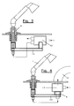
- 3 denotes a tub rim, on which a pot-shaped housing 7 of a changeover device is mounted, which has a tubular changeover slide 8, which is vertically displaceable in the housing 7 and which, under the load of a spring element, e.g. a coil spring 9, which is supported on the one hand on a shoulder of the change-over slide 8 and on the other hand on the bottom of the housing 7.
- a spring element e.g. a coil spring 9
- the upper end of the change-over slide 8 is provided with an internally conical receiving device 11 for a connecting cone of a hand shower 1.
- the changeover slide 8 of the changeover device is connected to a changeover valve 12, which alternatively opens or closes the opening to line 5 of the bath fittings and an opening to line 6 of hand shower 1.
- the spring element 9 is compressed by the weight of the hand shower.
- the change-over slide 8 covers a path 14 between the raised shower head according to FIG. 1 and the inserted shower head according to FIG. 2.
- the line 6 to the hand shower opens when the shower is raised according to FIG. 1 under the influence of the spring 9 of the changeover slide 8. 2, the spring 9 is compressed and the opening to line 6 is closed, while the opening to line 5 is opened.
- the changeover valve 12 from Umstellschieber 8 is influenced by a transmission device 13, which can be designed for example as a rod and can move in a horizontal plane under the influence of the Umstellschieber 8 up or down parallel to each other.
- the opening for the line 6 of the hand shower 1 is provided in the floor and the opening for a tub inlet 16 in the cover of the housing for the changeover valve 12.
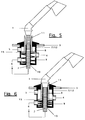
- the housing 7 of the changeover device is also the housing of the changeover valve 12, the changeover slide 8 being provided on the bottom side with a changeover piston 15 which forms the changeover valve and is loaded in the housing 7 by a spring 9 is.
- the hose 2 passes through the bottom of the housing 7 in an opening 10.
- the function of the changeover mechanism is similar to that of the previous exemplary embodiments, in which, with the hose pulled out according to FIG. 5, the piston is in its upper position, in which the feed line 4, such as FIG. 5 shows that the hand shower 1 is connected to the line 6, while when the hand shower 1 according to FIG. 6 is inserted, the piston presses down the spring 9, as a result of which the feed line 4 communicates with the line 5 of the bath fitting.
- control the changeover valve 12 and the transmission device 13 also mechanically, electrically or pneumatically.
Landscapes
- Engineering & Computer Science (AREA)
- General Engineering & Computer Science (AREA)
- Health & Medical Sciences (AREA)
- Life Sciences & Earth Sciences (AREA)
- Hydrology & Water Resources (AREA)
- Public Health (AREA)
- Water Supply & Treatment (AREA)
- Mechanical Engineering (AREA)
- Bathtubs, Showers, And Their Attachments (AREA)
- Domestic Plumbing Installations (AREA)
- Massaging Devices (AREA)
Abstract
Description
- Die Erfindung betrifft einen Umstellmechanismus zur Steuerung des Wasserflusses von Wannenzulauf- auf Handbrausebetrieb.
- Bis heute kommen folgende Varianten zum Einsatz:
- 1.
- 1 Wannenauslauf
4 Seitenventile
1 versenkbare Handbrause - 2.
- 1 Wannenauslauf
2 Seitenventile
1 versenkbare Handbrause
1 Umstellhahn - 3.
- 1 Wannenauslauf mit eingebautem Zugumsteller
2 Seitenventile
1 versenkbare Handbrause - Die Variante 1 hat den Nachteil, daß zu viele Löcher gebohrt werden müssen (6 Loch Variante) und durch die Menge der Teile am teuersten ist.
- Die Variante 2 benötigt zwar um 1 Loch weniger (5 Loch Variante), ist aber durch den notwendigen Umstellhahn immer noch zu aufwendig und zu teuer.
- Die Variante 3 ist die derzeit günstigste (4 Loch Variante), hat aber die Nachteile, daß eine Bohrung in den Körper des Auslaufes gebohrt, ein risikoreiches T-Stück am Auslauf angeschlossen werden muß, und außerdem ist es sehr unpraktisch , am konstruktionsbedingten kleinen Zugknopf eine Umstellung vorzunehmen. Auch hält sich die Durchflußmenge in Grenzen. Bei Wanneneinläufen neueren Designs ist auch oft gar keine Möglichkeit, einen Zugknopf unterzubringen, sei es aus technischen oder optischen Gründen.
- In jedem Fall muß in nachteiliger Weise ein Umstellmechanismus betätigt werden, welcher jeweils zwei verschiedene Wege freigibt, wie z.B. Umstellung von Handbrause auf Wanneneinlauf oder umgekehrt. Aufgabe der Erfindung ist die Schaffung von Maßnahmen, durch welche die Nachteile der bekannten Konstruktionen vermieden werden.
- Diese Aufgabe wird erfindungsgemäß dadurch gelöst, daß die Schlauchdurchführung der Handbrause zugleich eine Umschaltvorrichtung ist, wobei ein durch die Bewegung der Handbrause betätigbarer Umstellschieber der Umschaltvorrichtung mit einem Umschaltventil in Verbindung steht, welches zwischen einer die Öffnung zur Leitung der Handbrause freigebenden ersten Stellung und einer die Öffnung zur Leitung der Wannenarmaturen freigegebenen zweiten Stellung umschaltbar ist, wobei die erste Stellung bei herausgezogener und die zweite Stellung bei hineingesteckter Handbrause erzielbar ist.
- Durch diese Konstruktion wird gegenüber den bekannten Konstruktionen eine wesentliche Vereinfachung der Bedienung erzielt.
- Weitere Merkmale und Vorteile der Erfindung werden anhand einiger Ausführungsbeispiele unter Bezugnahme auf die beigefügten Zeichnungen nachfolgend näher erläutert.
- Fig. 1 zeigt einen teilweise schematischen Schnitt durch eine erste Ausführungsform des erfindungsgemäßen Umstellmechanismus bei herausgezogener Handbrause,
- Fig. 2 zeigt die Ausführungsform der Fig. 1 bei hineingesteckter Handbrause,
- Fig. 3 und 4 stellen schematisch Ausführungsformen dar, bei welchen eine Übertragungsvorrichtung zwischen Umschaltvorrichtung und Umschaltventil vorgesehen ist,
- Fig. 5 und 6 stellen eine spezielle Ausführungsform dar, bei der die Umschaltvorrichtung und das Umschaltventil in einem gemeinsamen Gehäuse angeordnet sind, und
- Fig. 7 zeigt eine spezielle Ausführungsform mit von der Umschaltvorrichtung getrenntem Umschaltventil.
- Bei der Ausführungsform des Umstellmechanismus nach den Fig. 1 und 2 ist mit 3 ein Wannenrand bezeichnet, an dem ein topfförmiges Gehäuse 7 einer Umschaltvorrichtung montiert ist, welches einen rohrförmigen, im Gehäuse 7 höhenverschiebbaren Umstellschieber 8 aufweist, der unter der Belastung eines Federelementes, z.B. einer Schraubenfeder 9,steht, die sich einerseits an einem Absatz des Umstellschiebers 8 und andererseits am Boden des Gehäuses 7 abstützt. Das obere Ende des Umstellschiebers 8 ist mit einer innenseitig kegelförmigen Aufnahmevorrichtung 11 für einen Anschlußkegel einer Handbrause 1 versehen. Der Umstellschieber 8 der Umschaltvorrichtung steht mit einem Umschaltventil 12 in Verbindung, welches alternativ die Öffnung zur Leitung 5 der Wannenarmaturen und eine Öffnung zur Leitung 6 der Handbrause 1 freigibt bzw. schließt. Das Federelement 9 wird durch das Gewicht der Handbrause zusammengedrückt. Zwischen abgehobener Brause nach Fig. 1 und eingesetzter Brause nach Fig. 2 legt der Umstellschieber 8 einen Weg 14 zurück.
- Wird die Zulaufleitung 4 freigegeben, öffnet bei abgehobener Brause nach Fig.1 unter dem Einfluß der Feder 9 der Umstellschieber 8 die Leitung 6 zur Handbrause. Bei eingesetzter Brause nach Fig. 2 wird die Feder 9 zusammengedrückt und die Öffnung zur Leitung 6 geschlossen, während die Öffnung zur Leitung 5 geöffnet wird.
- Während bei der Ausführungsform des Umstellmechanismus nach den Fig. 1 und 2 der Umstellschieber 9 in ein Gehäuse des Umschaltventils 12 unmittelbar eingreift, ist das Gehäuse des Umschaltventils 12 bei den Ausführungsformen des Umstellmechanismus nach Fig.3 und 4 seitlich angeordnet, wobei das Umschaltventil 12 vom Umstellschieber 8 über eine Übertragungsvorrichtung 13 beeinflußt wird, welche z.B. als Stänge ausgebildet sein kann und sich in horizontaler Ebene unter dem Einfluß des Umstellschiebers 8 nach oben oder unten jeweils parallel zu sich bewegen kann.
- Bei der Ausführungsform des Umstellmechanismus nach Fig. 4 ist die Öffnung für die Leitung 6 der Handbrause 1 im Boden und die Öffnung für einen Wanneneinlauf 16 im Deckel des Gehäuses für das Umschaltventil 12 vorgesehen.
- Bei der Ausführungsform des Umstellmechanismus nach den Fig. 5 und 6 ist das Gehäuse 7 der Umschaltvorrichtung zugleich das Gehäuse des Umschaltventils 12, wobei der Umstellschieber 8 bodenseitig mit einem Umstellkolben 15 versehen ist, welcher das Umschaltventil bildet und im Gehäuse 7 durch eine Feder 9 belastet ist. Der Schlauch 2 durchsetzt den Boden des Gehäuses 7 in einer Öffnung 10. Die Funktion des Umstellmechanismus ist ähnlich wie die den früheren Ausführungsbeispielen,in dem bei ausgezogenem Schlauch nach Fig. 5 der Kolben in seiner oberen Lage ist, in welcher die Zulaufleitung 4, wie Fig. 5 zeigt, mit der Leitung 6 der Handbrause 1 verbunden ist, während bei eingesetzter Handbrause 1 nach Fig. 6 der Kolben die Feder 9 niederdrückt, wodurch die Zuleitung 4 mit der Leitung 5 der Wannenarmatur kommuniziert.
- Die Konstruktion des Umstellmechanismus nach Fig. 7 ist ähnlich der nach den Fig. 3 und 4 mit dem Unterschied, daß das Umstellventil 12 ähnlich der Konstruktion nach den Fig. 5 und 6 mit einem Umstellkolben 15 versehen ist, wobei je ein Magnet 17, 17′ am umstellventilseitigen Ende der Übertragungsvorrichtung 13 und am Umstellkolben 15 vorgesehen ist. Die beiden Magnete sind zueinander abstoßend ausgerichtet, wobei der untere Magnet 17 im Führungsteil 18 geführt werden kann, sodaß bei herausgenommener Handbrause 1, wie in Fig. 7 dargestellt, unter dem Einfluß der Feder 9 und der Magneten 17, 17′ der Umstellkolben 15 nach oben gedrückt und die Leitung 4 mit der Leitung 6 verbunden wird. Wird die Handbrause 1 wieder zurückgesteckt, wird der Umstellschieber 8 nach unten gedrückt, entfernt sich der Magnet 17 vom Magnet 17′, sodaß die Magnete 17, 17′ nicht mehr aufeinander wirken und der Umstellkolben 15 wieder herunterfällt und somit die Leitung 5 zum Wanneneinlauf mit der Zulaufleitung 4 verbindet, wobei die zur Handbrause führende Leitung 6 gesperrt wird, was durch den sich im Gehäuse des Umschaltventils 12 aufbauenden Wasserdruck noch verstärkt wird.
- Selbstverständlich können im Rahmen der Erfindung auch verschiedene konstruktive Abänderungen vorgenommen werden. So ist es beispielsweise möglich, das Umstellventil 12 sowie die Übertragungsvorrichtung 13 auch mechanisch, elektrisch oder pneumatisch zu steuern.
Claims (7)
- Umstellmechanismus zur Steuerung des Wasserflusses von Wannenzulauf-auf Handbrausebetrieb, dadurch gekennzeichnet, daß die Schlauchdurchführung der Handbrause zugleich eine Umschaltvorrichtung ist, wobei ein durch die Bewegung der Handbrause (1) betätigbarer Umstellschieber (8) der Umschaltvorrichtung mit einem Umschaltventil (12) in Verbindung steht, welches zwischen einer die Öffnung zur Leitung (6) der Handbrause (1) freigebenden ersten Stellung und einer die Öffnung zur Leitung (5) der Wannenarmaturen freigegebenen zweiten Stellung umschaltbar ist, wobei die erste Stellung bei herausgezogener und die zweite Stellung bei hineingesteckter Handbrause (1) erzielbar ist.
- Umstellmechanismus nach Anspruch 1, dadurch gekennzeichnet, daß der Umstellschieber (8) der Umschaltvorrichtung von einem Federelement, vorzugsweise einer Schraubenfeder (9) in der Richtung auf die herausgezogene Stellung hin beaufschlagt ist.
- Umstellmechanismus nach Anspruch 2, dadurch gekennzeichnet, daß das Federelement (9) durch das Gewicht der in eine mit dem Umstellschieber verbundenen Aufnahmevorrichtung (11) eingesteckten Handbrause (1) zusammendrückbar ist.
- Umstellmechanismus nach Anspruch 1, dadurch gekennzeichnet, daß das Gehäuse (7) der Umschaltvorrichtung zugleich das Gehäuse des Umschaltventiles ist und das Umschaltventil durch einen Teil des Umschaltschiebers (8) gebildet ist, der in besagtem Gehäuse (7) verschiebbar gelagert und vorzugsweise von einem Federelement (9) beaufschlagt ist (Fig. 5, 6).
- Umstellmechanismus nach Anspruch 1, dadurch gekennzeichnet, daß das Gehäuse (7) der Umschaltvorrichtung vom Gehäuse (12) des Umschaltgetriebes baulich getrennt und allenfalls beabstandet davon vorgesehen ist, wobei das Umschaltventil durch eine Übertragungsvorrichtung (13) von der Umschaltvorrichtung her betätigbar ist (Fig. 3, 4, 7).
- Umstellmechanismus nach Anspruch 5, dadurch gekennzeichnet, daß eine flexible oder starre mechanische, hydraulische, pneumatische oder elektrisch/elektronische Übertragungsvorrichtung (13) zwischen Umschaltvorrichtung , Umschaltventil vorgesehen ist.
- Umstellmechanismus nach Anspruch 1, dadurch gekennzeichnet, daß das Umschaltventil mechanisch, pneumatisch, hydraulisch, elektrisch, magnetisch oder elektronisch betätigbar ist.
Applications Claiming Priority (4)
| Application Number | Priority Date | Filing Date | Title |
|---|---|---|---|
| AT2383/90 | 1990-11-23 | ||
| AT238390A AT396799B (de) | 1990-11-23 | 1990-11-23 | Umstellmechanismus zur steuerung des wasserflusses von wannenzulauf- auf handbrausebetrieb |
| AT2298/91 | 1991-11-19 | ||
| AT229891 | 1991-11-19 |
Publications (2)
| Publication Number | Publication Date |
|---|---|
| EP0487500A1 true EP0487500A1 (de) | 1992-05-27 |
| EP0487500B1 EP0487500B1 (de) | 1994-07-13 |
Family
ID=25598146
Family Applications (1)
| Application Number | Title | Priority Date | Filing Date |
|---|---|---|---|
| EP91890290A Expired - Lifetime EP0487500B1 (de) | 1990-11-23 | 1991-11-19 | Umstellmechanismus zur Steuerung des Wasserflusses von Wannenzulauf- auf Handbrausebetrieb |
Country Status (4)
| Country | Link |
|---|---|
| EP (1) | EP0487500B1 (de) |
| AT (1) | ATE108503T1 (de) |
| DE (1) | DE59102175D1 (de) |
| ES (1) | ES2062750T3 (de) |
Cited By (3)
| Publication number | Priority date | Publication date | Assignee | Title |
|---|---|---|---|---|
| WO2000022246A1 (de) * | 1998-10-15 | 2000-04-20 | Ideal-Standard Gmbh & Co. Ohg | Sanitäre armatur |
| US11053670B2 (en) | 2018-08-23 | 2021-07-06 | Spectrum Brands, Inc. | Faucet spray head alignment system |
| US11346088B2 (en) | 2018-08-23 | 2022-05-31 | Spectrum Brands, Inc. | Faucet head alignment system |
Citations (3)
| Publication number | Priority date | Publication date | Assignee | Title |
|---|---|---|---|---|
| DE1101303B (de) * | 1959-03-24 | 1961-03-02 | Hansa Metallwerke Ag | Wasch- oder Spueltischarmatur |
| FR1592930A (de) * | 1968-11-25 | 1970-05-19 | ||
| FR2438866A1 (fr) * | 1978-10-10 | 1980-05-09 | Leroy Robert | Systeme a galet excentre et a commande automatique et prolongee d'un debit |
-
1991
- 1991-11-19 EP EP91890290A patent/EP0487500B1/de not_active Expired - Lifetime
- 1991-11-19 ES ES91890290T patent/ES2062750T3/es not_active Expired - Lifetime
- 1991-11-19 DE DE59102175T patent/DE59102175D1/de not_active Expired - Fee Related
- 1991-11-19 AT AT91890290T patent/ATE108503T1/de not_active IP Right Cessation
Patent Citations (3)
| Publication number | Priority date | Publication date | Assignee | Title |
|---|---|---|---|---|
| DE1101303B (de) * | 1959-03-24 | 1961-03-02 | Hansa Metallwerke Ag | Wasch- oder Spueltischarmatur |
| FR1592930A (de) * | 1968-11-25 | 1970-05-19 | ||
| FR2438866A1 (fr) * | 1978-10-10 | 1980-05-09 | Leroy Robert | Systeme a galet excentre et a commande automatique et prolongee d'un debit |
Cited By (5)
| Publication number | Priority date | Publication date | Assignee | Title |
|---|---|---|---|---|
| WO2000022246A1 (de) * | 1998-10-15 | 2000-04-20 | Ideal-Standard Gmbh & Co. Ohg | Sanitäre armatur |
| US11053670B2 (en) | 2018-08-23 | 2021-07-06 | Spectrum Brands, Inc. | Faucet spray head alignment system |
| US11346088B2 (en) | 2018-08-23 | 2022-05-31 | Spectrum Brands, Inc. | Faucet head alignment system |
| US11859374B2 (en) | 2018-08-23 | 2024-01-02 | Assa Abloy Americas Residential Inc. | Faucet spray head alignment system |
| US12442164B2 (en) | 2018-08-23 | 2025-10-14 | Assa Abloy Americas Residential Inc. | Faucet spray head alignment system |
Also Published As
| Publication number | Publication date |
|---|---|
| ES2062750T3 (es) | 1994-12-16 |
| DE59102175D1 (de) | 1994-08-18 |
| ATE108503T1 (de) | 1994-07-15 |
| EP0487500B1 (de) | 1994-07-13 |
Similar Documents
| Publication | Publication Date | Title |
|---|---|---|
| DE60104248T2 (de) | Nach beiden RIchtungen vorgesteuerte Ventilanordnung | |
| DE3310080C2 (de) | Mischventil | |
| DE19623104C2 (de) | Als Einhebelmischer ausgebildete Sanitärarmatur | |
| DE69106676T2 (de) | Dichtes Handventil. | |
| DE3338064C2 (de) | ||
| EP4219990A2 (de) | Ventilbetätigungsvorrichtung | |
| DE3637068A1 (de) | Pneumatische antriebsvorrichtung fuer stellgeraete oder dergleichen | |
| DE60303505T2 (de) | Durchflussdrosselvorrichtung | |
| EP0487500B1 (de) | Umstellmechanismus zur Steuerung des Wasserflusses von Wannenzulauf- auf Handbrausebetrieb | |
| EP0061563B1 (de) | Wannenfüll- und Brausebatterie | |
| DE102004045490B3 (de) | Sanitäre Unterputzarmatur | |
| DE1550154A1 (de) | Umschaltbarer Wasserhahn | |
| DE3841911C2 (de) | Sanitärarmatur | |
| DE69401196T2 (de) | Abblasventil für ein dampfgefäss | |
| DE3811110A1 (de) | Kolbenantrieb | |
| DE2850291A1 (de) | Servobetaetigtes dreiwegeventil | |
| DE102004059926B3 (de) | Rückschlagventil mit unterschiedlichen Flussrichtungen | |
| DE4318837C2 (de) | Vorrichtung zum Auslösen und Unterbrechen des Wasserlaufs aus einer Wasseraustrittsöffnung | |
| EP1941196A1 (de) | Sanitäres umstellventil | |
| DE2933115A1 (de) | Einrichtung zum loesbaren anschluss einer abzweigleitung an eine druckleitung | |
| AT396799B (de) | Umstellmechanismus zur steuerung des wasserflusses von wannenzulauf- auf handbrausebetrieb | |
| EP3502365B1 (de) | Sanitärer gegenstand, insbesondere spülkasten oder ablauf- oder füllventil für einen spülkasten | |
| DE102006025785B3 (de) | Wasserauslaufvorrichtung für eine Sanitärarmatur | |
| DE4141172B4 (de) | Vorrichtung zum Umstellen eines Ventilgliedes an einer Sanitärarmatur | |
| DE3509295C2 (de) | Mischarmatur |
Legal Events
| Date | Code | Title | Description |
|---|---|---|---|
| PUAI | Public reference made under article 153(3) epc to a published international application that has entered the european phase |
Free format text: ORIGINAL CODE: 0009012 |
|
| AK | Designated contracting states |
Kind code of ref document: A1 Designated state(s): AT BE CH DE ES FR GB IT LI |
|
| 17P | Request for examination filed |
Effective date: 19920622 |
|
| 17Q | First examination report despatched |
Effective date: 19930414 |
|
| GRAA | (expected) grant |
Free format text: ORIGINAL CODE: 0009210 |
|
| AK | Designated contracting states |
Kind code of ref document: B1 Designated state(s): AT BE CH DE ES FR GB IT LI |
|
| REF | Corresponds to: |
Ref document number: 108503 Country of ref document: AT Date of ref document: 19940715 Kind code of ref document: T |
|
| REF | Corresponds to: |
Ref document number: 59102175 Country of ref document: DE Date of ref document: 19940818 |
|
| ITF | It: translation for a ep patent filed | ||
| ET | Fr: translation filed | ||
| REG | Reference to a national code |
Ref country code: ES Ref legal event code: FG2A Ref document number: 2062750 Country of ref document: ES Kind code of ref document: T3 |
|
| GBT | Gb: translation of ep patent filed (gb section 77(6)(a)/1977) |
Effective date: 19941128 |
|
| PGFP | Annual fee paid to national office [announced via postgrant information from national office to epo] |
Ref country code: AT Payment date: 19950127 Year of fee payment: 4 |
|
| PLBE | No opposition filed within time limit |
Free format text: ORIGINAL CODE: 0009261 |
|
| STAA | Information on the status of an ep patent application or granted ep patent |
Free format text: STATUS: NO OPPOSITION FILED WITHIN TIME LIMIT |
|
| 26N | No opposition filed | ||
| PG25 | Lapsed in a contracting state [announced via postgrant information from national office to epo] |
Ref country code: GB Effective date: 19951119 Ref country code: AT Effective date: 19951119 |
|
| PGFP | Annual fee paid to national office [announced via postgrant information from national office to epo] |
Ref country code: FR Payment date: 19951130 Year of fee payment: 5 |
|
| PGFP | Annual fee paid to national office [announced via postgrant information from national office to epo] |
Ref country code: BE Payment date: 19951201 Year of fee payment: 5 |
|
| PGFP | Annual fee paid to national office [announced via postgrant information from national office to epo] |
Ref country code: CH Payment date: 19951229 Year of fee payment: 5 |
|
| PGFP | Annual fee paid to national office [announced via postgrant information from national office to epo] |
Ref country code: ES Payment date: 19960201 Year of fee payment: 5 |
|
| GBPC | Gb: european patent ceased through non-payment of renewal fee |
Effective date: 19951119 |
|
| PG25 | Lapsed in a contracting state [announced via postgrant information from national office to epo] |
Ref country code: ES Free format text: LAPSE BECAUSE OF NON-PAYMENT OF DUE FEES Effective date: 19961120 |
|
| PGFP | Annual fee paid to national office [announced via postgrant information from national office to epo] |
Ref country code: DE Payment date: 19961125 Year of fee payment: 6 |
|
| PG25 | Lapsed in a contracting state [announced via postgrant information from national office to epo] |
Ref country code: LI Effective date: 19961130 Ref country code: CH Effective date: 19961130 Ref country code: BE Effective date: 19961130 |
|
| BERE | Be: lapsed |
Owner name: SCHMIEDL THOMAS Effective date: 19961130 |
|
| REG | Reference to a national code |
Ref country code: CH Ref legal event code: PL |
|
| PG25 | Lapsed in a contracting state [announced via postgrant information from national office to epo] |
Ref country code: FR Effective date: 19970731 |
|
| REG | Reference to a national code |
Ref country code: FR Ref legal event code: ST |
|
| PG25 | Lapsed in a contracting state [announced via postgrant information from national office to epo] |
Ref country code: DE Free format text: LAPSE BECAUSE OF NON-PAYMENT OF DUE FEES Effective date: 19980801 |
|
| REG | Reference to a national code |
Ref country code: ES Ref legal event code: FD2A Effective date: 19971213 |
|
| PG25 | Lapsed in a contracting state [announced via postgrant information from national office to epo] |
Ref country code: IT Free format text: LAPSE BECAUSE OF NON-PAYMENT OF DUE FEES Effective date: 20051119 |