EP0487501A1 - Dispositif pour un poste téléphonique alimenté par le courant de boucle - Google Patents
Dispositif pour un poste téléphonique alimenté par le courant de boucle Download PDFInfo
- Publication number
- EP0487501A1 EP0487501A1 EP91890291A EP91890291A EP0487501A1 EP 0487501 A1 EP0487501 A1 EP 0487501A1 EP 91890291 A EP91890291 A EP 91890291A EP 91890291 A EP91890291 A EP 91890291A EP 0487501 A1 EP0487501 A1 EP 0487501A1
- Authority
- EP
- European Patent Office
- Prior art keywords
- diode
- line
- switch
- control device
- subscriber line
- Prior art date
- Legal status (The legal status is an assumption and is not a legal conclusion. Google has not performed a legal analysis and makes no representation as to the accuracy of the status listed.)
- Granted
Links
Images


Classifications
-
- H—ELECTRICITY
- H04—ELECTRIC COMMUNICATION TECHNIQUE
- H04M—TELEPHONIC COMMUNICATION
- H04M1/00—Substation equipment, e.g. for use by subscribers
- H04M1/26—Devices for calling a subscriber
- H04M1/27—Devices whereby a plurality of signals may be stored simultaneously
-
- H—ELECTRICITY
- H04—ELECTRIC COMMUNICATION TECHNIQUE
- H04M—TELEPHONIC COMMUNICATION
- H04M1/00—Substation equipment, e.g. for use by subscribers
- H04M1/60—Substation equipment, e.g. for use by subscribers including speech amplifiers
- H04M1/6033—Substation equipment, e.g. for use by subscribers including speech amplifiers for providing handsfree use or a loudspeaker mode in telephone sets
-
- H—ELECTRICITY
- H04—ELECTRIC COMMUNICATION TECHNIQUE
- H04M—TELEPHONIC COMMUNICATION
- H04M1/00—Substation equipment, e.g. for use by subscribers
- H04M1/71—Substation extension arrangements
- H04M1/715—Substation extension arrangements using two or more extensions per line
Definitions
- the invention relates to a circuit arrangement for a loop-powered telephone subscriber station with monitoring of the connection setup and dialing options when the handset is on the hook, with a headset having a handset that can be connected to the subscriber line via an electronic line switch, and with a control device that controls the line switch Hook switches and a keyboard are connected and which is connected to the subscriber line via a limit circuit for supplying quiescent current.
- a method for electronically simulating the hook switch and the speakerphone button in a hands-free speakerphone with dialing option when the handset is on the hook in which an electronic control pulse generation combined with the keyboard of a dialing memory is provided and by one into one wire switching means looped into the subscriber line with assigned control device, the function of the loudspeaker key, the hands-free key, the fork switch contact and the number switch impulse contact are combined.
- the control device is supplied from an energy store which is kept in the charged state in the idle state by a small loop current or is formed by a backup battery provided in the subscriber station.
- a dialing module can be connected to the control device, the memory of which is also supplied with energy from the energy store in the idle state of the subscriber station in order to preserve the memory content.
- a first control device has outputs at which the switching states of the fork switch contact, the loudspeaker button or the hands-free button are signaled and which are connected to a further control device.
- the switching means for closing the subscriber loop is controlled via the first control device at the instigation of the further control device for transmitting dialing pulses.
- a parallel connection of a capacitor and a Z-diode is connected to the supply connections of the first control device and this combination is connected to the subscriber line via a current limiter, the current draw being limited to a value of less than 20 ⁇ A is.
- the current consumption of the control device must of course be below the limit value with a safety margin, but the current drawn from the subscriber line is constant regardless of this, because the excess current is dissipated through the Zener diode.
- the invention aims to develop a circuit arrangement of the type specified in such a way that the telephone subscriber station draws as little current as possible via the subscriber line in the idle state, but in order to seize the line in any way (actuating a key of the dialing module or removing it of the handset) the electricity required for this is available almost immediately, etc. regardless of whether the subscriber line has already been activated via the line switch or not.
- the quiescent current in the loop is limited to a predetermined value, regardless of whether the subscriber station is in the idle state or whether line seizure is initiated.
- the invention consists in a circuit arrangement of the type specified in essential in that the limiting circuit is formed by a voltage limiter.
- This measure does not consume a current specified by a current limiter in the idle state of the subscriber station, but only as much as the components or assemblies connected to the side of the open line switch facing the subscriber line actually consume in their ready state, and this current generally becomes considerable be smaller than the current supplied by the current limiter in the known circuit arrangements, because the current to be supplied by the current limiter must be dimensioned higher for safety reasons, so that reliable operation is ensured under all circumstances even in the event of unfavorable component tolerances and / or temperature conditions. Since the voltage limiter provided according to the invention can immediately supply a current which is greater than the quiescent current requirement when a line assignment is initiated, the provision of a special energy store for such sudden loads is unnecessary.
- the contact of the fork switch which is turned away from the fork switch input of the control device is preferably connected to the output of the voltage limiter. Since the voltage limiter can also deliver much higher currents than the quiescent current of the subscriber station, an immediate line assignment is possible without the presence of an energy store.
- a favorable embodiment of the voltage limiter without the need for additional components is that it is formed by a depletion-type MOS field-effect transistor, the drain electrode of which is connected to the positive wire and the gate electrode of which is connected to the negative wire of the subscriber line, and the source electrode of which is connected to the feed input the control device is connected.
- a further development of the circuit arrangement is that a Z-diode is inserted between the positive wire of the subscriber line and the sink electrode of the MOS field-effect transistor, that at an output of the headset, from which a diode is connected to the feed input connected to the source electrode of the MOS field-effect transistor the control device leads, a capacitor is connected, the other terminal of which is connected to the negative wire of the subscriber line, and that a further diode is provided, the cathode of which is connected to the drain electrode of the MOS field-effect transistor and the anode of which is connected to a node of the connecting line between the line switch and the headset is connected.
- a Z-diode is inserted between the positive wire of the subscriber line and the sink electrode of the MOS field-effect transistor, that at an output of the headset, from which a diode to the source electrode of the MOS Field effect transistor connected supply input of the control device, a capacitor is connected, the other connection is connected to the negative wire of the subscriber line, that a resistor is connected in series between the Zener diode and the voltage limiter, that an electronic switch is connected in parallel to the Zener diode and that the control input of the electronic switch is connected to the resistor, so that the switch bridges the Z-diode automatically when the current flowing through the series connection of Z-diode, resistor and voltage limiter exceeds a predetermined value.
- the inserted Z-diode results in a higher insulation resistance at low line voltages.
- the further diode connected after the line switch in the former embodiment ensures the voltage supply of the control device and the selector module from the point in time at which line assignment is initiated, as a result of which the line voltage drops below the breakdown voltage of the Z diode ;
- the capacitor is then charged by the voltage-supplied headset and the diode connected to it increases the potential at the source electrode of the field effect transistor to such an extent that it is blocked, while the control device is supplied with power via the diode via this diode.
- the voltage limiters of the other subscriber stations which are in idle state deliver their Line switches are thus open, no supply voltage for the control device with the selector module; As a result, none of the other subscribers can connect to the subscriber line that is already in use and the long-distance call is kept secret.
- concentrators are used for the line assignment to the central office.
- a concentrator is a switching system in which a large number of inputs have to be connected to a smaller number of outputs.
- Concentrators are often provided at remote locations and are powered by accumulators that are operated from the central office charged over unused lines. The energy available from the concentrator is therefore limited. If a subscriber connected to a concentrator initiates line seizure, the current that can be supplied by the concentrator is limited, in the order of magnitude about 270 ⁇ A in old systems and about 2 mA in newer systems. With such small current strengths available, the subscriber station should be able to hold the line assignment until it is allocated to the central office.
- the corresponding impedances for holding the line assignment are a maximum of 22 kOhm at 270 ⁇ A or a maximum of 2.25 kOhm at 2 mA.
- the security of the initiation of line seizure by subscribers who are supplied via a concentrator is considerably improved by the measures taken in the latter embodiment.
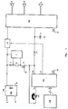
- FIG. 1 shows a basic block diagram of a circuit arrangement according to the invention
- FIGS. 2 and 3 show two developments of the circuit arrangement according to FIG.
- the telephone subscriber station is connected via a reverse polarity protection PB to the wires a and b of the subscriber line, the reverse polarity protection essentially containing a Graetz bridge rectifier and possibly surge arrester.
- the reverse polarity protection PB is followed by a line switch LS formed by a transistor, which performs the functions of the hook switch as well as the loop interruption in the case of direct current pulse selection and flash (clocked loop interruption).
- the line switch LS is controlled by a control device DC having a keyboard KB connected to it and having a selection module via its output LC.
- a headset SC which in the active state supplies the power supply to the control device with the dialing module takes over, can be connected to the subscriber line via the line switch LS.
- the headset SC is separated from the subscriber line by the line switch LS and the voltage at the connection VS of the control device DC for its supply voltage is then determined by the gate electrode source threshold voltage of a voltage limiter VL formed by a MOS field effect transistor.
- the insulation resistance is determined by the reverse polarity protection PB and the quiescent current absorbed by the control device DC in the order of less than 2 ⁇ A.
- the control device DC with the selector module can be influenced by a hook switch HS and the keyboard KB arranged in the form of an XY matrix.
- the keyboard KB contains keys for a loudspeaker device, for operating the subscriber station without lifting the handset and for direct memory access.
- the control device DC is supplied with a selection module from the voltage limiter VL and when the keyboard input is recognized as valid, the output signal from LC activates the line switch LS, the headset SC is connected to the subscriber line and the control device DC with the dial module is fed from the headset SC via a diode D1, and since this supply voltage is higher than the gate electrode source threshold voltage of the voltage limiter VL, the voltage limiter transistor is switched off. Then the subscriber station is in the active state.
- the negative supply connections Vss of the modules DC and SC are connected to the corresponding output of the reverse polarity protection PB, which carries the potential of the negative wire of the subscriber line.
- the gate electrode of the voltage limiter transistor is also connected to this output and the connection of a capacitor C facing away from the anode of the diode D1, which is provided for the screening of the supply voltage to be supplied by the headset SC.
- a Z-diode Z with a breakdown voltage of, for example, 18 V is connected between the output of the reverse polarity protection PB carrying the potential of the positive wire of the subscriber line and the sink electrode of the voltage limiter transistor, by means of which a line assignment is prevented when the voltage between wires a and b of the subscriber line is lower than the breakdown voltage of the Zener diode.
- the Z diode results in a very low leakage current at low line voltages, which ensures a very high insulation resistance.
- the line voltage when the subscriber line is occupied by a subscriber station connected in parallel is less than the breakdown voltage of the Zener diode Z, no voltage occurs at the supply connection VS of the control device DC and thus a line assignment is made impossible. If, on the other hand, the subscriber line is not occupied by a subscriber station connected in parallel, the line voltage is greater than the breakdown voltage of the Zener diode Z and the gate electrode source threshold voltage of the voltage limiter VL is available at the supply connection VS, so that when a line assignment is initiated via the keyboard KB or the hook switch HS the control device DC is on standby and the headset SC is connected to the subscriber line via the line switch LS.
- the line voltage breaks down to a value below the breakdown voltage of the Zener diode Z, but the control device DC is supplied with current via a diode D2 supplied until the capacitor C is charged to a higher voltage, whereby the voltage limiter VL is switched off.
- This solution according to FIG. 2 allows the transfer of a call from a partial connection station to another, connected partial connection station when the line is busy, since the starting time of the circuit arrangement is very short, namely the time between the occurrence of a voltage at the supply connection VS and the connection of the headset SC with the subscriber line via the line switch LS, as a result of which the subscriber station enters a state of low impedance for the line assignment, which time period is essentially due to the debouncing time of the pressed button or the hook switch HS connected to the input HI of the control device DC.
- FIG. 3 shows another embodiment of the circuit arrangement with properties that are largely similar to those of FIG. 2, but in contrast to FIG. 2, the diode D2 is omitted and the Z diode Z is bridged during an assignment process by an electronic switch L, whose actuation is controlled as a function of the current flowing through the series connection of the Zener diode Z, a resistor R and the voltage limiter VL.
- the Z-diode Z is bridged by the electronic switch L when the current flowing through the series connection exceeds a predetermined value.
Landscapes
- Engineering & Computer Science (AREA)
- Signal Processing (AREA)
- Devices For Supply Of Signal Current (AREA)
Applications Claiming Priority (2)
| Application Number | Priority Date | Filing Date | Title |
|---|---|---|---|
| AT2351/90 | 1990-11-20 | ||
| AT0235190A AT395665B (de) | 1990-11-20 | 1990-11-20 | Schaltungsanordnung fuer eine schleifenstromgespeiste fernsprechteilnehmerstation |
Publications (2)
| Publication Number | Publication Date |
|---|---|
| EP0487501A1 true EP0487501A1 (fr) | 1992-05-27 |
| EP0487501B1 EP0487501B1 (fr) | 1996-01-31 |
Family
ID=3532740
Family Applications (1)
| Application Number | Title | Priority Date | Filing Date |
|---|---|---|---|
| EP91890291A Expired - Lifetime EP0487501B1 (fr) | 1990-11-20 | 1991-11-20 | Dispositif pour un poste téléphonique alimenté par le courant de boucle |
Country Status (3)
| Country | Link |
|---|---|
| EP (1) | EP0487501B1 (fr) |
| AT (1) | AT395665B (fr) |
| DE (1) | DE59107343D1 (fr) |
Cited By (1)
| Publication number | Priority date | Publication date | Assignee | Title |
|---|---|---|---|---|
| DE19621550A1 (de) * | 1995-07-04 | 1997-01-16 | Samsung Electronics Co Ltd | Automatischer Abschaltkreis für einen Sprachpfad und automatisches Konvertierverfahren zu einem Bereitschaftszustand unter Vervollständigung eines Gesprächs über ein Lauthörtelefon in einem drahtlosen Telefon |
Citations (5)
| Publication number | Priority date | Publication date | Assignee | Title |
|---|---|---|---|---|
| DE2733661B2 (de) * | 1977-07-26 | 1981-05-27 | Siemens AG, 1000 Berlin und 8000 München | Fernsprecher mit akustischer Signalisierung des Wahlvorganges |
| DE2536201C2 (de) * | 1975-08-13 | 1982-06-03 | Standard Elektrik Lorenz Ag, 7000 Stuttgart | Schaltungsanordnung für Fernmeldeanlagen insbesondere für Fernsprechapparate zur Abgabe von Wählimpulsen mit einem Transistor |
| DE3203050C1 (de) * | 1982-01-30 | 1983-01-27 | Telefonbau Und Normalzeit Gmbh, 6000 Frankfurt | Schaltungsanordnung für über die Anschlußleitung gespeiste Teilnehmerapparate mit elektronischen Steuer- und Schaltmitteln in Fernmelde-, insbesondere Fernsprechanlagen |
| DE3609706C1 (de) * | 1986-03-21 | 1987-11-05 | Siemens Ag | Verfahren zur elektronischen Nachbildung des Gabelumschalters und der Freisprech-Lauthoertaste in einer Freisprech-Lauthoerfernsprechstation |
| DE3711897C2 (fr) * | 1987-04-08 | 1990-02-08 | Telenorma Telefonbau Und Normalzeit Gmbh, 6000 Frankfurt, De |
-
1990
- 1990-11-20 AT AT0235190A patent/AT395665B/de not_active IP Right Cessation
-
1991
- 1991-11-20 EP EP91890291A patent/EP0487501B1/fr not_active Expired - Lifetime
- 1991-11-20 DE DE59107343T patent/DE59107343D1/de not_active Expired - Fee Related
Patent Citations (5)
| Publication number | Priority date | Publication date | Assignee | Title |
|---|---|---|---|---|
| DE2536201C2 (de) * | 1975-08-13 | 1982-06-03 | Standard Elektrik Lorenz Ag, 7000 Stuttgart | Schaltungsanordnung für Fernmeldeanlagen insbesondere für Fernsprechapparate zur Abgabe von Wählimpulsen mit einem Transistor |
| DE2733661B2 (de) * | 1977-07-26 | 1981-05-27 | Siemens AG, 1000 Berlin und 8000 München | Fernsprecher mit akustischer Signalisierung des Wahlvorganges |
| DE3203050C1 (de) * | 1982-01-30 | 1983-01-27 | Telefonbau Und Normalzeit Gmbh, 6000 Frankfurt | Schaltungsanordnung für über die Anschlußleitung gespeiste Teilnehmerapparate mit elektronischen Steuer- und Schaltmitteln in Fernmelde-, insbesondere Fernsprechanlagen |
| DE3609706C1 (de) * | 1986-03-21 | 1987-11-05 | Siemens Ag | Verfahren zur elektronischen Nachbildung des Gabelumschalters und der Freisprech-Lauthoertaste in einer Freisprech-Lauthoerfernsprechstation |
| DE3711897C2 (fr) * | 1987-04-08 | 1990-02-08 | Telenorma Telefonbau Und Normalzeit Gmbh, 6000 Frankfurt, De |
Cited By (2)
| Publication number | Priority date | Publication date | Assignee | Title |
|---|---|---|---|---|
| DE19621550A1 (de) * | 1995-07-04 | 1997-01-16 | Samsung Electronics Co Ltd | Automatischer Abschaltkreis für einen Sprachpfad und automatisches Konvertierverfahren zu einem Bereitschaftszustand unter Vervollständigung eines Gesprächs über ein Lauthörtelefon in einem drahtlosen Telefon |
| DE19621550C2 (de) * | 1995-07-04 | 1999-09-23 | Samsung Electronics Co Ltd | Automatisches Freisprech-Verfahren für ein schnurloses Telefon sowie zugehöriger Schaltkreis |
Also Published As
| Publication number | Publication date |
|---|---|
| AT395665B (de) | 1993-02-25 |
| DE59107343D1 (de) | 1996-03-14 |
| ATA235190A (de) | 1992-06-15 |
| EP0487501B1 (fr) | 1996-01-31 |
Similar Documents
| Publication | Publication Date | Title |
|---|---|---|
| DE2062235C3 (de) | Schaltungsanordnung für das Halten von Verbindungswegen in einer Fernmeldeinsbesondere Fernsprechanlage | |
| EP0275352B1 (fr) | Circuit de protection des appareils électroniques contre la surcharge | |
| DE69726328T2 (de) | Überspannungsschutz für eine Telefonleitungs-Schnittstelle | |
| EP0487501B1 (fr) | Dispositif pour un poste téléphonique alimenté par le courant de boucle | |
| DE2522957C3 (de) | Schaltungsanordnung für über ihre Anschlußleitungen gespeiste Teilnehmerstationen mit Impulstastwahl in Fernmelde-, insbesondere Fernsprechanlagen | |
| DE3628922C2 (fr) | ||
| DE2221717B2 (de) | Teilnehmerschaltung für Fernsprechvermittlungsanlagen zur Zuführung des Rufstromes an die Teilnehmerstation und zur Feststellung des Schleifenzustandes | |
| DE2733476A1 (de) | Teilnehmerleitungsschaltung fuer eine tastenfernsprechanlage | |
| DE69231822T2 (de) | Treiberschnittstelle für einen telephonischen Leitungschalter zum Einschalten einer Sprechschaltung unabhängig von der Leistungspolarität | |
| DE2949513C2 (de) | Notrufanlage | |
| DE69012014T2 (de) | Fernsprechapparat mit Verbindung mit der Teilnehmerleitung ohne Abnahme des Hörers. | |
| DE3640707C2 (fr) | ||
| DE3007468A1 (de) | Teilnehmerspeiseanordnung | |
| DE1173538B (de) | Schaltungsanordnung fuer Fernmelde-, insbesondere Fernsprechanlagen mit Belegungsstromkreisen | |
| DE3528645C2 (fr) | ||
| DE3627025C2 (fr) | ||
| DE1195352B (de) | Elektrischer Verteiler in Form einer im Ring geschalteten Zaehlkette | |
| DE3725882C2 (de) | Verfahren und Vorrichtung zur Übertragung von Signalen einer Fernsprecheinrichtung | |
| DE3130087C5 (de) | Schaltungsanordnung für ein dynamisches Mikrofon | |
| DE3921940A1 (de) | Schaltungsanordnung zur anschaltung mehrerer teilnehmer an eine gemeinsame anschlussleitung | |
| DE2718990A1 (de) | Schleifenextender oder schleifenerweiterungseinrichtung fuer fernsprecheinrichtungen | |
| DE1250507B (fr) | ||
| DE1144345B (de) | Schaltungsanordnung zum Empfangen von Gleichstromsignalen in Fernmelde-, insbesondere Fernsprechvermittlungsanlagen | |
| DE9104908U1 (de) | Schaltungsanordnung zum automatischen Umschalten wenigstens zweier Sprechstellen | |
| DE2445040A1 (de) | Schaltungsanordnung fuer einen fernsprechapparat |
Legal Events
| Date | Code | Title | Description |
|---|---|---|---|
| PUAI | Public reference made under article 153(3) epc to a published international application that has entered the european phase |
Free format text: ORIGINAL CODE: 0009012 |
|
| AK | Designated contracting states |
Kind code of ref document: A1 Designated state(s): BE CH DE DK ES FR GB GR IT LI LU NL SE |
|
| 17P | Request for examination filed |
Effective date: 19920613 |
|
| RAP1 | Party data changed (applicant data changed or rights of an application transferred) |
Owner name: AUSTRIA MIKRO SYSTEME INTERNATIONAL AKTIENGESELLSC |
|
| 17Q | First examination report despatched |
Effective date: 19940712 |
|
| GRAA | (expected) grant |
Free format text: ORIGINAL CODE: 0009210 |
|
| AK | Designated contracting states |
Kind code of ref document: B1 Designated state(s): BE CH DE DK ES FR GB GR IT LI LU NL SE |
|
| PG25 | Lapsed in a contracting state [announced via postgrant information from national office to epo] |
Ref country code: IT Free format text: LAPSE BECAUSE OF FAILURE TO SUBMIT A TRANSLATION OF THE DESCRIPTION OR TO PAY THE FEE WITHIN THE PRE;WARNING: LAPSES OF ITALIAN PATENTS WITH EFFECTIVE DATE BEFORE 2007 MAY HAVE OCCURRED AT ANY TIME BEFORE 2007. THE CORRECT EFFECTIVE DATE MAY BE DIFFERENT FROM THE ONE RECORDED.SCRIBED TIME-LIMIT Effective date: 19960131 Ref country code: BE Effective date: 19960131 Ref country code: NL Free format text: LAPSE BECAUSE OF FAILURE TO SUBMIT A TRANSLATION OF THE DESCRIPTION OR TO PAY THE FEE WITHIN THE PRESCRIBED TIME-LIMIT Effective date: 19960131 Ref country code: ES Free format text: THE PATENT HAS BEEN ANNULLED BY A DECISION OF A NATIONAL AUTHORITY Effective date: 19960131 Ref country code: GB Effective date: 19960131 Ref country code: FR Effective date: 19960131 Ref country code: DK Effective date: 19960131 Ref country code: GR Free format text: LAPSE BECAUSE OF FAILURE TO SUBMIT A TRANSLATION OF THE DESCRIPTION OR TO PAY THE FEE WITHIN THE PRESCRIBED TIME-LIMIT Effective date: 19960131 |
|
| REF | Corresponds to: |
Ref document number: 59107343 Country of ref document: DE Date of ref document: 19960314 |
|
| PG25 | Lapsed in a contracting state [announced via postgrant information from national office to epo] |
Ref country code: SE Effective date: 19960430 |
|
| EN | Fr: translation not filed | ||
| NLV1 | Nl: lapsed or annulled due to failure to fulfill the requirements of art. 29p and 29m of the patents act | ||
| GBV | Gb: ep patent (uk) treated as always having been void in accordance with gb section 77(7)/1977 [no translation filed] |
Effective date: 19960131 |
|
| PG25 | Lapsed in a contracting state [announced via postgrant information from national office to epo] |
Ref country code: CH Effective date: 19961130 Ref country code: LU Free format text: LAPSE BECAUSE OF NON-PAYMENT OF DUE FEES Effective date: 19961130 Ref country code: LI Effective date: 19961130 |
|
| PLBE | No opposition filed within time limit |
Free format text: ORIGINAL CODE: 0009261 |
|
| STAA | Information on the status of an ep patent application or granted ep patent |
Free format text: STATUS: NO OPPOSITION FILED WITHIN TIME LIMIT |
|
| 26N | No opposition filed | ||
| PG25 | Lapsed in a contracting state [announced via postgrant information from national office to epo] |
Ref country code: DE Effective date: 19970801 |
|
| REG | Reference to a national code |
Ref country code: CH Ref legal event code: EP Ref country code: CH Ref legal event code: PL |
|
| REG | Reference to a national code |
Ref country code: CH Ref legal event code: EP |