EP0487543B1 - Brieflocher - Google Patents
Brieflocher Download PDFInfo
- Publication number
- EP0487543B1 EP0487543B1 EP90910678A EP90910678A EP0487543B1 EP 0487543 B1 EP0487543 B1 EP 0487543B1 EP 90910678 A EP90910678 A EP 90910678A EP 90910678 A EP90910678 A EP 90910678A EP 0487543 B1 EP0487543 B1 EP 0487543B1
- Authority
- EP
- European Patent Office
- Prior art keywords
- pressure lever
- slide
- guide
- abutment
- elongated hole
- Prior art date
- Legal status (The legal status is an assumption and is not a legal conclusion. Google has not performed a legal analysis and makes no representation as to the accuracy of the status listed.)
- Expired - Lifetime
Links
Images


Classifications
-
- B—PERFORMING OPERATIONS; TRANSPORTING
- B26—HAND CUTTING TOOLS; CUTTING; SEVERING
- B26F—PERFORATING; PUNCHING; CUTTING-OUT; STAMPING-OUT; SEVERING BY MEANS OTHER THAN CUTTING
- B26F1/00—Perforating; Punching; Cutting-out; Stamping-out; Apparatus therefor
- B26F1/32—Hand-held perforating or punching apparatus, e.g. awls
- B26F1/36—Punching or perforating pliers
Definitions
- the invention relates to a letter punch with a lower part, a pivotally mounted on lateral bearing blocks of the lower part, which is guided on the lower part displaceably guided against the restoring force of a spring pressure lever and a stop shoulder arranged on the lower part or on the bearing blocks, against which an arranged on the pressure lever stop member below the action of the restoring force of the spring.
- Such a letter punch is e.g. through delivery and use by customers of the specialist world from the priority date of this patent application.
- the stop members have the function of end stops for the pressure lever in the non-actuated and actuated state.
- the invention has for its object to provide a letter punch of the type mentioned, which has an integrated in the hole punch, easy to manufacture and assemble hold-down for the pressure lever.
- the invention consists essentially in the fact that the stop member is designed as a one-piece slide made of plastic which can be displaced in an elongated hole in the pressure lever between two end positions and which forms a hold-down stop against the stop shoulder in the one end position when the pressure lever is depressed and the swivel path of the in the other end position Releases the pressure lever.
- an actuating head is formed on the slide with a neck part which extends through the elongated hole extending transversely in the pressure lever and which has projections which overlap the longitudinal side edges of the elongated hole and which advantageously has its projections aligned in the course of the assembly in the longitudinal direction of the elongated hole Elongated hole can be inserted and locked by rotating the slide by 90 ° together with the slide in a sliding guide aligned parallel to the elongated hole on the pressure lever.
- the pressure lever advantageously has two guide ribs which are arranged at a distance from one another and are oriented parallel to the elongated hole and form the sliding guide, while the slide has a stop edge facing the stop shoulder, a wedge-shaped or laterally offset edge against the stop edge and guided on one of the guide ribs of the pressure lever first guide edge and one opposite the stop edge and the first guide edge on the second guide rib of the pressure lever has guided second leading edge.
- a latching tongue preferably arranged on the side of the second guide edge, can be provided on the slide, with which it can be locked in the end position which releases the pivoting path of the pressure lever on a latching member of the pressure lever.
- the stop edge of the slide is advantageously wedge-shaped relative to the slide plane, so that the major part of the hold-down forces exerted by the return spring is transmitted to the inside of the pressure lever and not only to the relatively narrow second guide rib.
- the guide ribs, the elongated hole and the counter-latching element for the latching tongue are expediently arranged in the region of an apron which delimits the pressure lever on the end face at the bottom.
- the cast hole punch shown in FIGS. 1 and 2 essentially consists of a lower hole part 10, two bearing blocks 14 arranged laterally on the lower part 10 and a pressure lever 18 which can be pivoted to a limited extent on the bearing blocks about a pivot axis 16.
- the pressure lever 18 has two laterally downwards curved bearing tabs 20 which overlap the outside of the bearing blocks 14 and an apron 22 which is bent downward on the end face and connects the bearing tabs to one another.
- upward-facing cantilevers 24 are formed, which engage under the apron 22 of the pressure lever and against whose upper edge, which forms a stop shoulder 26, a guide and stop rib 30 which projects inward on the pressure lever 18 and is designed as an end stop, under the action of Spring 28 strikes.
- a slide 32 is arranged such that it can be displaced transversely, which reaches through to the front with a neck part 33 and an actuating head 34 through an elongated hole 36 in the apron 22.
- the slide 32 designed as an injection molded part made of plastic is aligned with its actuating head 34 in the longitudinal direction of the elongated hole 36 during assembly Projections 38 inserted through the elongated hole and then rotated by 90 °, so that the projections 38 positively overlap the longitudinal side edges of the elongated hole.
- the lateral guide edges 40, 42 of the slide 32 snap into the area between the two guide ribs 44, 30 protruding towards the inside of the apron.
- the lower guide edge 40 is inclined relative to the slide plane. Adjacent to it is a stop edge 48 which is inclined towards the opposite side and which, in engagement with the stop shoulder 26 of the adjacent arm 24, serves as a hold-down stop for the pressure lever 18.
- the upper guide and deflection rib 30 for the slide 32 also forms the end stop which abuts against the stop shoulder 26 of the arm 24.
- a latching tongue 50 which engages with a latching member 52 in the end position of the slide moved out of the stop position into a counter-latching, not shown, on the pressure lever.
Landscapes
- Life Sciences & Earth Sciences (AREA)
- Forests & Forestry (AREA)
- Engineering & Computer Science (AREA)
- Mechanical Engineering (AREA)
- Perforating, Stamping-Out Or Severing By Means Other Than Cutting (AREA)
- Press Drives And Press Lines (AREA)
Abstract
Description
- Die Erfindung betrifft einen Brieflocher mit einem Unterteil, einem an seitlichen Lagerböcken des Unterteils schwenkbar gelagerten, auf am Unterteil verschiebbar geführte Lochstempel gegen die Rückstellkraft einer Feder einwirkenden Druckhebel und einer am Unterteil oder an den Lagerböcken angeordneten Anschlagschulter, gegen die ein am Druckhebel angeordnetes Anschlagorgan unter der Einwirkung der Rückstellkraft der Feder anschlägt.
- Ein derartiger Brieflocher ist z.B. durch Lieferung und Benutzung durch Kunden der Fachwelt von dem Prioritätstag dieser Patentanmeldung bekannt geworden.
- Bei bekannten Brieflochern dieser Art haben die Anschlagorgane die Funktion von Endanschlägen für den Druckhebel im nicht betätigten und betätigten Zustand. Andererseits ist es vor allem bei Brieflochern mit ausladenden Druckhebeln beispielsweise für Transport- und Lagerzwecke erwünscht, den Druckhebel in einer niedergedrückten Stellung zu arretieren. Für Transportzwecke werden meist Niederhalteorgane aus Holz oder Kunststoff verwendet, die nach Gebrauch weggeworfen werden.
- Der Erfindung liegt die Aufgabe zugrunde, einen Brieflocher der eingangs angegebenen Art zu schaffen, der einen im Locher integrierten, einfach herstellbaren und montierbaren Niederhalter für den Druckhebel aufweist.
- Zur Lösung dieser Aufgabe werden die im Patentanspruch 1 angegebenen Merkmale vorgeschlagen. Weitere vorteilhafte Ausgestaltungen und Weiterbildungen der Erfindung ergeben sich aus den abhängigen Ansprüchen.
- Die Erfindung besteht im wesentlichen darin, daß das Anschlagorgan als in einem Langloch des Druckhebels zwischen zwei Endstellungen verschiebbarer einstückiger Schieber aus Kunststoff ausgebildet ist, der in der einen Endstellung bei niedergedrücktem Druckhebel einen gegen die Anschlagschulter anliegenden Niederhalteanschlag bildet und in der anderen Endstellung den Schwenkweg des Druckhebels freigibt.
- Gemäß einer bevorzugten Ausgestaltung der Erfindung ist an dem Schieber ein mit einem Halsteil durch das im Druckhebel quer verlaufende Langloch hindurchgreifender Betätigungskopf angeformt, der die Längsseitenränder des Langloches übergreifende Vorsprünge aufweist und der vorteilhafterweise mit seinen im Zuge der Montage in Längsrichtung des Langlochs ausgerichteten Vorsprüngen durch das Langloch hindurchsteckbar und durch Drehen des Schiebers um 90° gemeinsam mit dem Schieber in einer parallel zum Langloch ausgerichteten Schiebeführung am Druckhebel einrastbar ist. Vorteilhafterweise weist der Druckhebel zu diesem Zweck zwei im Abstand voneinander angeordnete, parallel zum Langloch ausgerichtete, die Schiebeführung bildende Führungsrippen auf, während der Schieber eine der Anschlagschulter zugewandte Anschlagkante, eine gegenüber der Anschlagkante keilförmig angestellte oder seitlich abgesetzte, an einer der Führungsrippen des Druckhebels geführte erste Führungskante und eine der Anschlagkante und der ersten Führungskante gegenüberliegende, an der zweiten Führungsrippe des Druckhebels geführte zweite Führungskante aufweist. Weiter kann an dem Schieber eine vorzugsweise auf der Seite der zweiten Führungskante angeordnete Rastzunge vorgesehen werden, mit der er in der den Schwenkweg des Druckhebels freigebenden Endstellung an einem Rastorgan des Druckhebels arretierbar ist.
- Die Anschlagkante des Schiebers ist vorteilhafterweise gegenüber der Schieberebene keilförmig angestellt, so daß der überwiegende Teil der durch die Rückstellfeder ausgeübten Niederhaltekräfte auf die Innenseite des Druckhebels und nicht nur auf die relativ schmale zweite Führungsrippe übertragen wird. Die Führungsrippen, das Langloch und das Gegenrastorgan für die Rastzunge sind zweckmäßig im Bereich einer den Druckhebel stirn-Seitig nach unten begrenzenden Schürze angeordnet.
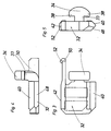
- Im folgenden wird die Erfindung anhand eines in der Zeichnung in schematischer Weise dargestellten Ausführungsbeispiels näher erläutert. Es zeigen
- Fig. 1
- einen Brieflocher mit Niederhalteorgan in schaubildlicher Darstellung;
- Fig. 2
- einen teilweise geschnittenen seitlichen Umriß des Lochers nach Fig. 1 in Niederhaltestellung;
- Fig. 3
- eine Draufsicht auf den Niederhalteschieber;
- Fig. 4
- eine Seitenansicht des Niederhalteschiebers nach Fig. 3;
- Fig. 5
- eine Stirnseitenansicht des Niederhalteschiebers nach Fig. 3 und 4.
- Der in den Fig. 1 und 2 dargestellte Gußlocher besteht im wesentlichen aus einem Loche-runterteil 10, zwei am Unterteil 10 seitlich angeordneten Lagerböcken 14 und einem an den Lagerböcken um eine Schwenkachse 16 begrenzt verschwenkbaren Druckhebel 18. Der Druckhebel 18 weist zwei seitlich nach unten gebogene, die Lagerböcke 14 außenseitig übergreifende Lagerlappen 20 sowie eine stirnseitig nach unten gebogene, die Lagerlappen miteinander verbindende Schürze 22 auf. An den Lagerböcken 14 sind stirnseitig nach oben weisende Ausleger 24 angeformt, die unter die Schürze 22 des Druckhebels greifen und gegen deren eine Anschlagschulter 26 bildende Oberkante eine am Druckhebel 18 nach innen überstehende, als Endanschlag ausgebildete, Führungs -und Anschlagrippe 30 unter der Einwirkung der Feder 28 anschlägt.
- Weiter ist im Bereich der Schürze 22 des Druckhebels ein Schieber 32 querverschiebbar angeordnet, der mit einem Halsteil 33 und einem Betätigungskopf 34 durch ein Langloch 36 in der Schürze 22 zur Vorderseite hindurchgreift.
- Der als Spritzgußteil aus Kunststoff ausgebildete Schieber 32 wird bei der Montage mit seinem Betätigungskopf 34 mit in Längsrichtung des Langlochs 36 ausgerichteten Vorsprüngen 38 durch das Langloch hindurchgesteckt und anschließend um 90° gedreht, so daß die Vorsprünge 38 die Längsseitenränder des Langlochs formschlüssig übergreifen. Gleichzeitig rasten die seitlichen Führungskanten 40,42 des Schiebers 32 in den Bereich zwischen den beiden nach der Schürzeninnenseite überstehenden Führungsrippen 44,30 ein. Die untere Führungskante 40 ist schräg gegenüber der Schieberebene angestellt. Ihr benachbart ist eine nach der gegenüberliegenden Seite schräg angestellte Anschlagkante 48 angeordnet, die im Eingriff mit der Anschlagschulter 26 des benachbarten Auslegers 24 als Niederhalteanschlag für den Druckhebel 18 dient. Die obere Führungs -und Auschlagrippe 30 für den Schieber 32 bildet zugleich den gegen die Anschlagschulter 26 des Auslegers 24 anschlagenden Endanschlag. In der Verlängerung der oberen Führungskante 42 erstreckt sich eine Rastzunge 50, die mit einem Rastorgan 52 in der aus der Anschlagstellung herausgerückten Endstellung des Schiebers in eine nicht dargestellte Gegenrast am Druckhebel einrastet.
Claims (8)
- Brieflocher mit einem Unterteil (10), einem an seitlichen Lagerböcken (14) des Unterteils schwenkbar gelagerten, auf am Unterteil verschiebbar geführte Lochstempel gegen die Rückstellkraft einer Feder (28) einwirkenden Druckhebel (18) und einer am Unterteil oder an den Lagerböcken angeordneten Anschlagschulter (26), gegen die ein am Druckhebel (18) angeordnetes Anschlagorgan (32) unter der Einwirkung der Rückstellkraft der Feder (28) anschlägt, dadurch gekennzeichnet, daß das Anschlagorgan als in einem Langloch (36) zwischen zwei Endstellungen verschiebbarer einstückiger Schieber (32) aus Kunststoff ausgebildet ist, der in der einen Endstellung bei niedergedrücktem Druckhebel (18) einen gegen die Anschlagschulter (26) anliegenden Niederhalteanschlag bildet und in der anderen Endstellung den Schwenkweg des Druckhebels (18) freigibt.
- Brieflocher nach Anspruch 1, dadurch gekennzeich net, daß an dem Schieber (32) ein mit einem Halsteil (33) durch das im Druckhebel (18) quer verlaufende Langloch (36) hindurchgreifender Betätigungskopf (34) angeformt ist, der die Längsseitenränder des Langloches (36) übergreifende Vorsprünge (38) aufweist.
- Brieflocher nach Anspruch 2, dadurch gekennzeich net, daß der Betätigungskopf (34) mit seinen im Zuge der Montage in Längsrichtung des Langlochs (36) ausgerichteten Vorsprüngen (38) durch das Langloch (36) hindurchsteckbar und durch Drehen des Schiebers um 90° gemeinsam mit dem Schieber (32) in einer parallel zum Langloch (36) ausgerichteten Schiebeführung am Druckhebel (18) einrastbar ist.
- Brieflocher nach einem der Ansprüche 1 bis 3, da durch gekennzeichnet, daß der Druckhebel (18) zwei im Abstand voneinander angeordnete, parallel zum Langloch (36) ausgerichtete, eine Schiebeführung bildende Führungsrippen (44,30) aufweist, und daß der Schieber (32) eine der Anschlagschulter (26) zugewandte Anschlagkante (48), eine gegenüber der Anschlagkante (48) keilförmig angestellte oder seitlich abgesetzte, an einer der Führungsrippen (44) des Druckhebels (18) geführte erste Führungskante (40) und eine der Anschlagkante (48) und der ersten Führunqskante (40) gegenüberliegende, an der zweiten Führungs -und Anschlagrippe (30) des Druckhebels (18) geführte zweite Führungskante (42) aufweist.
- Brieflocher nach Anspruch 4, dadurch gekennzeich net, daß der Schieber (32) eine auf der Seite der zweiten Führungskante (42) angeordnete Rastzunge (50) aufweist, mit der er in der den Schwenkweg des Druckhebels (18) freigebenden Endstellung an einem Gegenrastorgan des Druckhebels (18) arretierbar ist.
- Brieflocher nach Anspruch 4 oder 5, dadurch ge kennzeichnet, daß die Anschlagkante (48) des Schiebers (32) gegenüber der Schieberebene keilförmig angestellt ist.
- Brieflocher nach einem der Ansprüche 4 bis 6, da durch gekennzeichnet, daß die zweite Führungs -und Anschlagrippe (30) zugleich als gegen die Anschlagschulter (26) anschlagendes Endanschlagorgan ausgebildet ist.
- Brieflocher nach einem der Ansprüche 4 bis 7, da durch gekennzeichnet, daß die Führungsrippen (44,30), das Langloch (36) und das Gegenrastorgan für die Rastzunge (50) im Bereich einer dem Druckhebel (18) stirnseitig nach unten begrenzenden Schürze (22) angeordnet sind.
Priority Applications (1)
| Application Number | Priority Date | Filing Date | Title |
|---|---|---|---|
| AT90910678T ATE96362T1 (de) | 1989-08-14 | 1990-07-04 | Brieflocher. |
Applications Claiming Priority (2)
| Application Number | Priority Date | Filing Date | Title |
|---|---|---|---|
| DE3926836 | 1989-08-14 | ||
| DE3926836 | 1989-08-14 |
Publications (2)
| Publication Number | Publication Date |
|---|---|
| EP0487543A1 EP0487543A1 (de) | 1992-06-03 |
| EP0487543B1 true EP0487543B1 (de) | 1993-10-27 |
Family
ID=6387095
Family Applications (1)
| Application Number | Title | Priority Date | Filing Date |
|---|---|---|---|
| EP90910678A Expired - Lifetime EP0487543B1 (de) | 1989-08-14 | 1990-07-04 | Brieflocher |
Country Status (8)
| Country | Link |
|---|---|
| EP (1) | EP0487543B1 (de) |
| JP (1) | JPH04506185A (de) |
| KR (1) | KR920700859A (de) |
| CN (1) | CN1019770B (de) |
| DD (1) | DD297109A5 (de) |
| DE (1) | DE59003266D1 (de) |
| ES (1) | ES2045934T3 (de) |
| WO (1) | WO1991002632A1 (de) |
Families Citing this family (3)
| Publication number | Priority date | Publication date | Assignee | Title |
|---|---|---|---|---|
| KR20130129947A (ko) * | 2010-10-21 | 2013-11-29 | 레고 에이/에스 | 완구 조립 세트 |
| BR112013009548A2 (pt) * | 2010-10-21 | 2016-07-12 | Lego As | conjunto de construção de brinquedo |
| JP5820183B2 (ja) * | 2011-08-12 | 2015-11-24 | Seiオプティフロンティア株式会社 | 光ファイバカッタ及び光ファイバカッタユニット |
Family Cites Families (2)
| Publication number | Priority date | Publication date | Assignee | Title |
|---|---|---|---|---|
| US3714857A (en) * | 1970-09-09 | 1973-02-06 | Swingline Inc | Punch |
| JPS5212391B2 (de) * | 1972-10-02 | 1977-04-06 |
-
1990
- 1990-07-04 ES ES90910678T patent/ES2045934T3/es not_active Expired - Lifetime
- 1990-07-04 DE DE90910678T patent/DE59003266D1/de not_active Expired - Fee Related
- 1990-07-04 WO PCT/EP1990/001070 patent/WO1991002632A1/de not_active Ceased
- 1990-07-04 KR KR1019910701486A patent/KR920700859A/ko not_active Ceased
- 1990-07-04 EP EP90910678A patent/EP0487543B1/de not_active Expired - Lifetime
- 1990-07-04 JP JP2509961A patent/JPH04506185A/ja active Pending
- 1990-08-14 DD DD90343440A patent/DD297109A5/de not_active IP Right Cessation
- 1990-08-14 CN CN90106976A patent/CN1019770B/zh not_active Expired
Also Published As
| Publication number | Publication date |
|---|---|
| ES2045934T3 (es) | 1994-01-16 |
| DE59003266D1 (de) | 1993-12-02 |
| JPH04506185A (ja) | 1992-10-29 |
| WO1991002632A1 (de) | 1991-03-07 |
| CN1049473A (zh) | 1991-02-27 |
| EP0487543A1 (de) | 1992-06-03 |
| CN1019770B (zh) | 1992-12-30 |
| DD297109A5 (de) | 1992-01-02 |
| KR920700859A (ko) | 1992-08-10 |
Similar Documents
| Publication | Publication Date | Title |
|---|---|---|
| DE68926887T2 (de) | Verschiebbares Scharnier insbesondere für Glas- oder Flaschenhalter | |
| DE69413948T2 (de) | Behälter mit verriegelbarem deckel | |
| DE69500681T2 (de) | Verriegelung eines beweglichen Bauteiles in einem Kraftfahrzeugsitz | |
| DE2908140A1 (de) | Handbetaetigter locher zum lochen von papier o.dgl. | |
| DE69808566T2 (de) | Papierschneider | |
| DE69408080T2 (de) | Verbesserungen an werkzeugen zur erzeugung von befestigungspunkten an blechen durch kaltformung | |
| DE2603439A1 (de) | Stanzkopf zum befestigen von muttern | |
| EP0487543B1 (de) | Brieflocher | |
| DE4021645A1 (de) | Brieflocher | |
| DE3030878C2 (de) | ||
| EP1253676A2 (de) | Elektrischer Steckverbinder | |
| DE2350463C2 (de) | Anschlußvorrichtung für Scheibenwischer | |
| EP0487542B1 (de) | Brieflocher | |
| DE8611988U1 (de) | Befestigungsvorrichtung vom Druckknopftyp | |
| EP0283676A2 (de) | Brieflocher | |
| EP0649361B1 (de) | Heftklammergerät | |
| WO1991002636A1 (de) | Brieflocher mit anschlagschiene | |
| EP0232704B1 (de) | Rastverschluss, insbesondere für Pelzmäntel | |
| EP1177941B1 (de) | Rückstellvorrichtung für einen Blinkerschalter in Kraftfahrzeugen | |
| DE3301789A1 (de) | Anzeige-drucktaste | |
| DE3013735A1 (de) | Vorrichtung zum befestigen einer aus einem tastenkopf und einem tastenstoessel bestehenden taste in einer gehaeuseschale | |
| EP0141214B1 (de) | Zunge für einen Vorreiberverschluss | |
| DE4312993C2 (de) | Kartenleser | |
| DE2536591C3 (de) | Mechanisch feste Verbindung zwischen einem ersten und einem senkrecht zu dem ersten angeordneten zweiten Blechteil | |
| CH621082A5 (en) | Letter perforator |
Legal Events
| Date | Code | Title | Description |
|---|---|---|---|
| PUAI | Public reference made under article 153(3) epc to a published international application that has entered the european phase |
Free format text: ORIGINAL CODE: 0009012 |
|
| 17P | Request for examination filed |
Effective date: 19910701 |
|
| AK | Designated contracting states |
Kind code of ref document: A1 Designated state(s): AT CH DE ES FR GB IT LI NL SE |
|
| 17Q | First examination report despatched |
Effective date: 19921204 |
|
| RAP1 | Party data changed (applicant data changed or rights of an application transferred) |
Owner name: LOUIS LEITZ KG |
|
| GRAA | (expected) grant |
Free format text: ORIGINAL CODE: 0009210 |
|
| AK | Designated contracting states |
Kind code of ref document: B1 Designated state(s): AT CH DE ES FR GB IT LI NL SE |
|
| REF | Corresponds to: |
Ref document number: 96362 Country of ref document: AT Date of ref document: 19931115 Kind code of ref document: T |
|
| REF | Corresponds to: |
Ref document number: 59003266 Country of ref document: DE Date of ref document: 19931202 |
|
| GBT | Gb: translation of ep patent filed (gb section 77(6)(a)/1977) |
Effective date: 19931116 |
|
| ET | Fr: translation filed | ||
| ITF | It: translation for a ep patent filed | ||
| REG | Reference to a national code |
Ref country code: ES Ref legal event code: FG2A Ref document number: 2045934 Country of ref document: ES Kind code of ref document: T3 |
|
| PGFP | Annual fee paid to national office [announced via postgrant information from national office to epo] |
Ref country code: CH Payment date: 19940627 Year of fee payment: 5 |
|
| PLBE | No opposition filed within time limit |
Free format text: ORIGINAL CODE: 0009261 |
|
| STAA | Information on the status of an ep patent application or granted ep patent |
Free format text: STATUS: NO OPPOSITION FILED WITHIN TIME LIMIT |
|
| 26N | No opposition filed | ||
| EAL | Se: european patent in force in sweden |
Ref document number: 90910678.3 |
|
| PGFP | Annual fee paid to national office [announced via postgrant information from national office to epo] |
Ref country code: SE Payment date: 19950619 Year of fee payment: 6 |
|
| PG25 | Lapsed in a contracting state [announced via postgrant information from national office to epo] |
Ref country code: CH Effective date: 19950731 Ref country code: LI Effective date: 19950731 |
|
| REG | Reference to a national code |
Ref country code: CH Ref legal event code: PL |
|
| PGFP | Annual fee paid to national office [announced via postgrant information from national office to epo] |
Ref country code: FR Payment date: 19960610 Year of fee payment: 7 |
|
| PG25 | Lapsed in a contracting state [announced via postgrant information from national office to epo] |
Ref country code: SE Effective date: 19960705 |
|
| PGFP | Annual fee paid to national office [announced via postgrant information from national office to epo] |
Ref country code: ES Payment date: 19960711 Year of fee payment: 7 |
|
| EUG | Se: european patent has lapsed |
Ref document number: 90910678.3 |
|
| PGFP | Annual fee paid to national office [announced via postgrant information from national office to epo] |
Ref country code: AT Payment date: 19970616 Year of fee payment: 8 |
|
| PG25 | Lapsed in a contracting state [announced via postgrant information from national office to epo] |
Ref country code: ES Free format text: LAPSE BECAUSE OF EXPIRATION OF PROTECTION Effective date: 19970705 |
|
| PG25 | Lapsed in a contracting state [announced via postgrant information from national office to epo] |
Ref country code: FR Free format text: LAPSE BECAUSE OF NON-PAYMENT OF DUE FEES Effective date: 19980331 |
|
| REG | Reference to a national code |
Ref country code: FR Ref legal event code: ST |
|
| PG25 | Lapsed in a contracting state [announced via postgrant information from national office to epo] |
Ref country code: AT Free format text: LAPSE BECAUSE OF NON-PAYMENT OF DUE FEES Effective date: 19980704 |
|
| REG | Reference to a national code |
Ref country code: GB Ref legal event code: 732E |
|
| NLS | Nl: assignments of ep-patents |
Owner name: LOUIS LEITZ INTERNATIONAL GMBH & CO. |
|
| REG | Reference to a national code |
Ref country code: ES Ref legal event code: FD2A Effective date: 20010201 |
|
| REG | Reference to a national code |
Ref country code: GB Ref legal event code: IF02 |
|
| NLT1 | Nl: modifications of names registered in virtue of documents presented to the patent office pursuant to art. 16 a, paragraph 1 |
Owner name: ESSELTE LEITZ GMBH & CO KG |
|
| REG | Reference to a national code |
Ref country code: GB Ref legal event code: 732E |
|
| PGFP | Annual fee paid to national office [announced via postgrant information from national office to epo] |
Ref country code: GB Payment date: 20060613 Year of fee payment: 17 |
|
| PGFP | Annual fee paid to national office [announced via postgrant information from national office to epo] |
Ref country code: IT Payment date: 20060731 Year of fee payment: 17 |
|
| PGFP | Annual fee paid to national office [announced via postgrant information from national office to epo] |
Ref country code: NL Payment date: 20070716 Year of fee payment: 18 |
|
| GBPC | Gb: european patent ceased through non-payment of renewal fee |
Effective date: 20070704 |
|
| PG25 | Lapsed in a contracting state [announced via postgrant information from national office to epo] |
Ref country code: GB Free format text: LAPSE BECAUSE OF NON-PAYMENT OF DUE FEES Effective date: 20070704 |
|
| PGFP | Annual fee paid to national office [announced via postgrant information from national office to epo] |
Ref country code: DE Payment date: 20080723 Year of fee payment: 19 |
|
| NLV4 | Nl: lapsed or anulled due to non-payment of the annual fee |
Effective date: 20090201 |
|
| PG25 | Lapsed in a contracting state [announced via postgrant information from national office to epo] |
Ref country code: NL Free format text: LAPSE BECAUSE OF NON-PAYMENT OF DUE FEES Effective date: 20090201 |
|
| PG25 | Lapsed in a contracting state [announced via postgrant information from national office to epo] |
Ref country code: IT Free format text: LAPSE BECAUSE OF NON-PAYMENT OF DUE FEES Effective date: 20070704 |
|
| PG25 | Lapsed in a contracting state [announced via postgrant information from national office to epo] |
Ref country code: DE Free format text: LAPSE BECAUSE OF NON-PAYMENT OF DUE FEES Effective date: 20100202 |