EP0487588B1 - Schlagzähmachender endverstärkter buchbindestreifen - Google Patents
Schlagzähmachender endverstärkter buchbindestreifen Download PDFInfo
- Publication number
- EP0487588B1 EP0487588B1 EP90912693A EP90912693A EP0487588B1 EP 0487588 B1 EP0487588 B1 EP 0487588B1 EP 90912693 A EP90912693 A EP 90912693A EP 90912693 A EP90912693 A EP 90912693A EP 0487588 B1 EP0487588 B1 EP 0487588B1
- Authority
- EP
- European Patent Office
- Prior art keywords
- strip
- studs
- integral
- spacing
- binding
- Prior art date
- Legal status (The legal status is an assumption and is not a legal conclusion. Google has not performed a legal analysis and makes no representation as to the accuracy of the status listed.)
- Expired - Lifetime
Links
Images

Classifications
-
- B—PERFORMING OPERATIONS; TRANSPORTING
- B42—BOOKBINDING; ALBUMS; FILES; SPECIAL PRINTED MATTER
- B42F—SHEETS TEMPORARILY ATTACHED TOGETHER; FILING APPLIANCES; FILE CARDS; INDEXING
- B42F13/00—Filing appliances with means for engaging perforations or slots
- B42F13/12—Filing appliances with means for engaging perforations or slots with pillars, posts, rods, or tubes
- B42F13/14—Filing appliances with means for engaging perforations or slots with pillars, posts, rods, or tubes with clamping or locking means
-
- B—PERFORMING OPERATIONS; TRANSPORTING
- B42—BOOKBINDING; ALBUMS; FILES; SPECIAL PRINTED MATTER
- B42B—PERMANENTLY ATTACHING TOGETHER SHEETS, QUIRES OR SIGNATURES OR PERMANENTLY ATTACHING OBJECTS THERETO
- B42B5/00—Permanently attaching together sheets, quires or signatures otherwise than by stitching
- B42B5/08—Permanently attaching together sheets, quires or signatures otherwise than by stitching by finger, claw or ring-like elements passing through the sheets, quires or signatures
-
- B—PERFORMING OPERATIONS; TRANSPORTING
- B42—BOOKBINDING; ALBUMS; FILES; SPECIAL PRINTED MATTER
- B42D—BOOKS; BOOK COVERS; LOOSE LEAVES; PRINTED MATTER CHARACTERISED BY IDENTIFICATION OR SECURITY FEATURES; PRINTED MATTER OF SPECIAL FORMAT OR STYLE NOT OTHERWISE PROVIDED FOR; DEVICES FOR USE THEREWITH AND NOT OTHERWISE PROVIDED FOR; MOVABLE-STRIP WRITING OR READING APPARATUS
- B42D1/00—Books or other bound products
- B42D1/06—Books or other bound products in which the fillings and covers are united by other means
Definitions
- the invention relates to a non-loose leaf binding system for use in permanently binding a stack of paper sheets formed with a plurality of margin apertures.
- the round studs of the '013 design may also be employed for binding a paper sheets stack having punched rectangular holes.
- a particular spacing of two studs at one end of the strip is provided so as to prevent lateral displacement of the punch paper in the stack.
- the present invention provides a non-loose leaf binding system for use in permanently binding a stack of paper sheets formed with a plurality of margin apertures, comprising a first elongate strip having a plurality of integral spaced-apart straight studs projecting orthogonally therefrom and a second elongate strip formed with spaced-apart apertures corresponding to the spacing of the integral studs on the first strip, the integral studs being dimensioned and positioned to fit into the apertures in the second strip when the strips are assembled with a stack of sheets mounted on the integral studs between the strips, characterized by the first strip having a central portion having a first series of adjacent ones of the integral studs at a first fixed spacing and wherein each end portion of the first strip comprises a cluster of at least three integral studs which three integral studs are positioned so that they define a second fixed and essentially equal spacing between two consecutive studs, the second spacing being smaller than any spacing between two consecutive studs in the central portion of the first strip such that in use
- the invention also provides a non-loose leaf binding system for use in permanently binding a stack of paper sheets formed with a plurality of margin apertures, comprising a first elongate strip having a plurality of integral spaced-apart straight studs projecting orthogonally therefrom and a second elongate strip formed with spaced-apart strip apertures, corresponding to the spacing of the integral studs on the first strip, the integral studs being dimensioned and positioned to fit into the strip apertures in the second strip with a stack of paper sheets between the strips, characterized by the first strip having a central portion having the integral studs dimensioned with a first cross-sectional area and a pair of first strip end portions extending from the central portions having the integral studs thereon dimensioned with a second cross-sectional area greater than the first cross-sectional area of the integral studs in the first strip central portion, such that the binding strips upon assembly with the stack of paper sheets are end-strengthened for impact resistance.
- the first integral stud-containing strip thus has a mid-span portion having the integral studs at a first fixed spacing, generally as in the standard VeloBind configuration.
- integral studs having a closer spacing and/or having a thicker diameter so as to end-reinforce the binding at both its ends.
- VeloBind stud cut-off and riveting machines need be altered only slightly to accommodate the above described strips having closer end spacing and stud thicknesses.
- Other non-VeloBind machines can also cut-off and upset the stud ends extending from the second strip after assembly of the strips on opposite sides of a properly and correspondingly punched stack of paper sheets.
- Fig. 1 illustrates a prior art bookbinding 10 positioned on a marginal edge 14 of a stack 11 of punched-hole paper sheets 31.
- the binding 10 comprises a first strip 22 having a series of integral studs extending therefrom, through the punched holes in the paper stack marginal edge and subsequently upset or riveted to form a head 12 extending in a circular recess 28 in an apertured and recessed second strip 21.
- the impacting of a so-bound book or report is shown as a result of a drop on a hard floor surface 20.
- the initial result of such drop when an end of the book hits surface 20 are impact forces indicated by arrows 33 in Fig.
- the strips are generally semi-rigid polyvinyl chloride or other, preferably thermoplastic material such as ABS plastic or polystyrene. This action will result as shown in Fig.
- FIG. 5 shows the binding of the prior art before assembly on a marginal edge of stack of paper sheets.
- strip 22 has a series of equally-spaced thin integral studs 23 extending orthogonally therefrom typically eleven in number for an 11 inch (28 cm) long strip.
- Strip 21 is the same length as strip 22 and contains equally spaced circular apertures 27 and circular recesses 28 into which cut-off ends of the studs are upsetted, i.e. riveted after assembly on a paper sheets stack.
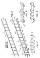
- Fig. 6 shows the binding of the present invention where a first strip 42 has a series of integral studs 43b, 43c, 43d, 43e, 43f, 43g, 43h, 43i, and 43j extending equally spaced over what is termed a "mid-space portion" of the strip.
- Such spacing in the aforesaid 28 cm strip generally is at a distance of 2.5 cm stud center-to-center, thus forming a stud first fixed spacing in the mid-span portion.
- Additional integral studs 43a and 45a are formed at one end of strip 42 and additional studs 43k and 45b are formed at the opposite end of strip 42 with a second fixed spacing smaller than the first fixed spacing of the other studs with respect to their adjacent studs.
- This lesser stud second fixed spacing for the 28 cm strip is generally 1.25 cm stud center-to-center. Preferably the second fixed spacing ranges from about 30% to about 70% of its first fixed spacing.
- Strip 41 is of the same overall length as strip 42 and has correspondingly space apertures 44 and recesses 48 over a mid-span portion of the strip and more closely spaced apertures and recesses over each of the end portions 49 and 50 of the strip to receive, respectively, studs 43a, 45q, 43b, and studs 43j, 45b, 43k when assembled on a marginal edge of a paper sheets stack generally in the same manner as shown in Figs. 1 and 3 of the prior art binding.
- the end portions are reinforced so that impact forces of the same or of a substantial higher degree of magnitude that caused failure of the discussed prior art binding do not cause failure of the improved binding.
- Fig., 7 shows a top view of strip 42 clearly showing the relatively wide first fixed spacing X in the mid-span portion of the strip between studs 43b and 43c and the relatively narrow second fixed spacing Y in the end portions of the strip 42 between studs 43b and 45a and between studs 45a and 43a.
- Fig. 8 shows a second embodiment of the invention wherein a pair of integral studs 55a and 55b are provided at a still smaller second fixed spacing z between studs 43a and 43b. Studs 55a and 55b may have centers which are staggered from the central longitudinal axis 60 of the strip which contains the centers of studs 43a, 43b, and 43c. Further, an additional oval stud 56 may be provided to further increase impact resistance.
- Fig. 9 shows a third embodiment wherein a strip 62 is end-reinforced at each end by one or more integral studs 65a, 65b, and 65c having a larger cross-sectional area, for example, 0.43 mm in diameter, and hence more impact resistance, than the relatively thin and relatively small cross-area (0.25 mm in diameter) studs in the mid-span portion of the strip, represented by studs 43b and 43c.
- the studs 65a, 65b, and 65c may be at variously smaller stud center-to-center spacings than the first fixed spacing between studs 43b and 43c, in the mid-span portion.
- the studs may have various cross-sectional shapes, such as square or rectangular, other than the illustrated round and oval studs.
Landscapes
- Engineering & Computer Science (AREA)
- Business, Economics & Management (AREA)
- Educational Administration (AREA)
- Educational Technology (AREA)
- Textile Engineering (AREA)
- Folding Of Thin Sheet-Like Materials, Special Discharging Devices, And Others (AREA)
- Laminated Bodies (AREA)
- Adhesives Or Adhesive Processes (AREA)
- Reinforced Plastic Materials (AREA)
- Slide Fasteners, Snap Fasteners, And Hook Fasteners (AREA)
- Connection Of Plates (AREA)
- Buffer Packaging (AREA)
- Package Frames And Binding Bands (AREA)
- Clamps And Clips (AREA)
- Supports For Pipes And Cables (AREA)
Claims (9)
- Nichtloseblatt-Bindesystem zur Verwendung zum dauerhaften Binden eines Stapels von Papierblättern, die mit mehreren Randlöchern versehen sind, mit einem ersten langgestreckten Streifen (42), der eine Vielzahl von in einem Stück damit ausgebildeten beabstandeten geraden Stiften (43, 45, 55, 56, 65) aufweist, die orthogonal davon vorstehen, und mit einem zweiten langgestreckten Streifen (41), der mit beabstandeten Löchern (44) entsprechend dem Abstand der in einem Stück am ersten Streifen vorgesehenen Stiften ausgebildet sind, wobei die in einem Stück ausgebildeten Stifte so bemessen und angeordnet sind, daß sie in die Öffnungen im zweiten Streifen passen, wenn die Streifen mit einem auf den in einem Stück ausgebildeten Stiften zwischen den Streifen angeordneten Blattstapel zusammengesetzt werden, dadurch gekennzeichnet, daß der erste Streifen (42) einen mittleren Teil umfaßt, der eine erste Reihe (43c-43j) von benachbarten in einem Stück ausgebildeten Stiften in einem ersten Abstand aufweist, wobei jeder Endabschnitt des ersten Streifens eine Gruppe von wenigstens drei in einem Stück damit ausgebildeten Stiften (43a, 45a, 43b) umfaßt, welche in einem Stück damit ausgebildeten Stifte so angeordnet sind, daß sie einen zweiten festen und im wesentlichen gleichen Abstand zwischen zwei aufeinanderfolgenden Stiften haben, wobei der zweite Abstand kleiner als irgendein Abstand zwischen zwei aufeinanderfolgenden Stiften am mittleren Teil des ersten Streifens ist, so daß bei der Benutzung die Bindestreifen (41, 42) zur Schlagfestigkeit endverstärkt sind.
- Bindesystem nach Anspruch 1, bei dem der zweite feste Abstand bei etwa 30 % bis etwa 70 % des ersten festen Abstandes liegt.
- Bindesystem nach Anspruch 2, bei dem der zweite feste Abstand gleich etwa der Hälfte des ersten festen Abstandes ist.
- Bindesystem nach Anspruch 1, 2 oder 3, bei dem die in einem Stück am ersten Streifen (42) ausgebildeten Stifte (43, 45, 55, 56, 65) gestaucht oder genietet sind, so daß Köpfe gebildet sind, die sich in kreisförmige Aussparungen an den Löchern (44) im zweiten Streifen (40) erstrecken.
- Bindesystem nach Anspruch 1, 2, 3 oder 4, bei dem wenigstens einer (55a, 55b) der Stifte an jedem Endabschnitt des ersten Streifens entlang der mittleren Längsachse (60) des ersten Streifens versetzt und von der mittleren Längsachse (60) des ersten Streifens abgesetzt ist.
- Bindesystem nach einem vorhergehenden Anspruch, bei dem jeder der in einem Stück am mittleren Teil des Streifens ausgebildeten Stifte eine erste Querschnittsfläche hat und bei dem jeder Endabschnitt des ersten Streifens wenigstens einen in einem Stück damit ausgebildeten Stift (56; 65a-c) aufweist, der eine Querschnittsfläche hat, die größer als die Querschnittsfläche jedes der in einem Stück am mittleren Teil ausgebildeten Stifte ist.
- Bindesystem nach Anspruch 6, bei dem ein in einem Stück ausgebildeter Stift (56), der jedem Ende des ersten Streifens (42) am nächsten liegt, eine größere Querschnittsfläche als die der in einem Stück ausgebildeten Stifte (43, 45) hat, die über den mittleren Teil des ersten Stiftes verlaufen.
- Bindesystem nach Anspruch 6 mit zwei in einem Stück ausgebildeten Stiften (65a, 65b) an jedem Ende des ersten Streifens (42), wobei die Paare aus in einem Stück ausgebildeten Stiften jeweils eine größere Querschnittsfläche und einen zweiten engeren Abstand als die in einem Stück ausgebildeten Stifte haben, die über den mittleren Teil des ersten Streifens verlaufen.
- Nichtloseblatt-Bindesystem zur Verwendung zum dauerhaften Binden eines Stapels von Papierblättern, die mit mehreren Randlöchern versehen sind, mit einem ersten langgestreckten Streifen (42), der mehrere in einem Stück damit ausgebildete beabstandete gerade Stifte (43, 45, 55, 56, 65) aufweist, die orthogonal davon vorstehen, und mit einem zweiten langgestreckten Streifen (41), der mit beabstandeten Streifenöffnungen (44) entsprechend dem Abstand der in einem Stück am ersten Streifen ausgebildeten Stifte ausgebildet ist, wobei die in einem Stück ausgebildeten Stifte so bemessen und angeordnet sind, daß sie in die Löcher im zweiten Streifen mit einem zwischen den Streifen angeordneten Stapel von Papierblättern passen, dadurch gekennzeichnet, daß der erste Streifen einen mittleren Teil mit in einem Stück ausgebildeten Stiften (43, 45, 55), die mit einer ersten Querschnittsfläche dimensioniert sind, und zwei Endabschnitten des ersten Streifens aufweist, die vom mittleren Teil ausgehen und in einem Stück daran ausgebildete Stifte (65a-65c) aufweisen, die mit einer zweiten Querschnittsfläche größer als die erste Querschnittsfläche der in einem Stück ausgebildeten Stifte am mittleren Teil des ersten Streifens dimensioniert sind, derart, daß die Bindestreifen nach dem Zusammensetzen mit dem Stapel von Papierblättern zur Schlagfestigkeit endverstärkt sind.
Applications Claiming Priority (3)
| Application Number | Priority Date | Filing Date | Title |
|---|---|---|---|
| US394340 | 1982-07-01 | ||
| US07/394,340 US4973085A (en) | 1989-08-15 | 1989-08-15 | End-reinforced bookbinding strip for impact resistance |
| PCT/US1990/004562 WO1991002655A1 (en) | 1989-08-15 | 1990-08-10 | End-reinforced bookbinding strip for impact resistance |
Publications (3)
| Publication Number | Publication Date |
|---|---|
| EP0487588A1 EP0487588A1 (de) | 1992-06-03 |
| EP0487588A4 EP0487588A4 (en) | 1992-07-22 |
| EP0487588B1 true EP0487588B1 (de) | 1995-06-07 |
Family
ID=23558538
Family Applications (1)
| Application Number | Title | Priority Date | Filing Date |
|---|---|---|---|
| EP90912693A Expired - Lifetime EP0487588B1 (de) | 1989-08-15 | 1990-08-10 | Schlagzähmachender endverstärkter buchbindestreifen |
Country Status (10)
| Country | Link |
|---|---|
| US (1) | US4973085A (de) |
| EP (1) | EP0487588B1 (de) |
| JP (1) | JPH05501088A (de) |
| AT (1) | ATE123448T1 (de) |
| AU (1) | AU641179B2 (de) |
| CA (1) | CA2065006C (de) |
| DE (1) | DE69019974T2 (de) |
| ES (1) | ES2072444T3 (de) |
| IE (1) | IE67336B1 (de) |
| WO (1) | WO1991002655A1 (de) |
Families Citing this family (5)
| Publication number | Priority date | Publication date | Assignee | Title |
|---|---|---|---|---|
| US20040240967A1 (en) * | 2001-08-29 | 2004-12-02 | Phillip Crudo | Binding elements for binding a wide range of thicknesses of stacks of sheets |
| USD481760S1 (en) | 2002-10-04 | 2003-11-04 | King Jim Co., Ltd. | Binding apparatus |
| CA2573096A1 (en) | 2004-07-12 | 2006-02-16 | General Binding Corporation | Binding element and plurality of binding elements particularly suited for automated processes |
| USD528600S1 (en) | 2004-08-23 | 2006-09-19 | King Jim Co., Ltd. | Binding apparatus |
| USD620977S1 (en) | 2006-08-04 | 2010-08-03 | General Binding Corporation | Binding element |
Family Cites Families (6)
| Publication number | Priority date | Publication date | Assignee | Title |
|---|---|---|---|---|
| US4369013A (en) * | 1969-02-13 | 1983-01-18 | Velo-Bind, Inc. | Bookbinding strips |
| US3744821A (en) * | 1971-09-23 | 1973-07-10 | Abildgaard Lab | Book and method of forming same |
| US4650426A (en) * | 1977-05-23 | 1987-03-17 | Curriculum Associates, Inc. | Skill evaluating apparatus and method |
| US4309046A (en) * | 1977-07-01 | 1982-01-05 | Minnesota Mining And Manufacturing Company | Binding element |
| US4175340A (en) * | 1977-09-30 | 1979-11-27 | Deutch Howard E | Form book |
| EP0170464B1 (de) * | 1984-07-27 | 1990-06-20 | Velo-Bind, Inc. | Heftstreifen für rechteckig gelochtes Papier |
-
1989
- 1989-08-15 US US07/394,340 patent/US4973085A/en not_active Expired - Lifetime
-
1990
- 1990-08-10 JP JP2512073A patent/JPH05501088A/ja active Pending
- 1990-08-10 DE DE69019974T patent/DE69019974T2/de not_active Expired - Fee Related
- 1990-08-10 AU AU62846/90A patent/AU641179B2/en not_active Ceased
- 1990-08-10 WO PCT/US1990/004562 patent/WO1991002655A1/en not_active Ceased
- 1990-08-10 EP EP90912693A patent/EP0487588B1/de not_active Expired - Lifetime
- 1990-08-10 ES ES90912693T patent/ES2072444T3/es not_active Expired - Lifetime
- 1990-08-10 AT AT90912693T patent/ATE123448T1/de not_active IP Right Cessation
- 1990-08-10 CA CA002065006A patent/CA2065006C/en not_active Expired - Fee Related
- 1990-08-13 IE IE292590A patent/IE67336B1/en not_active IP Right Cessation
Also Published As
| Publication number | Publication date |
|---|---|
| IE902925A1 (en) | 1991-02-27 |
| US4973085A (en) | 1990-11-27 |
| ES2072444T3 (es) | 1995-07-16 |
| WO1991002655A1 (en) | 1991-03-07 |
| JPH05501088A (ja) | 1993-03-04 |
| ATE123448T1 (de) | 1995-06-15 |
| AU6284690A (en) | 1991-04-03 |
| CA2065006A1 (en) | 1991-02-16 |
| AU641179B2 (en) | 1993-09-16 |
| EP0487588A4 (en) | 1992-07-22 |
| DE69019974D1 (de) | 1995-07-13 |
| CA2065006C (en) | 1999-07-27 |
| IE67336B1 (en) | 1996-03-20 |
| DE69019974T2 (de) | 1995-10-05 |
| EP0487588A1 (de) | 1992-06-03 |
Similar Documents
| Publication | Publication Date | Title |
|---|---|---|
| US5102167A (en) | End-reinforced bookbinding strip for impact resistance | |
| US5393155A (en) | Ring binder housing | |
| DE2248408C2 (de) | Behälter zur Aufnahme einer Kassette mit einem bandförmigen Aufzeichnungsträger | |
| US4730972A (en) | Book binding method, paper sheets binder and adjustable spine | |
| US4743048A (en) | Multi-fold adjustable binder, book, and method | |
| EP0487588B1 (de) | Schlagzähmachender endverstärkter buchbindestreifen | |
| US4139216A (en) | Wrap around cover | |
| CA1246112A (en) | Binding strips for rectangular hole punched paper | |
| EP0179652B1 (de) | Buchbindestreifen | |
| EP0396306B1 (de) | Kernschicht für eine Sandwichplatte | |
| US4950097A (en) | File folder and method of manufacture | |
| US4997208A (en) | Security binding | |
| WO2001036162A1 (en) | Staple driver with convex edge and pointed protrusions at the ends | |
| US4374627A (en) | Binder for perforated sheets or the like | |
| JP2673626B2 (ja) | ホルダ | |
| US4309046A (en) | Binding element | |
| US5123675A (en) | Clamp lock binding | |
| US1727108A (en) | Loose-leaf binder | |
| US2232058A (en) | Binder | |
| US5102252A (en) | Binder | |
| EP0471024A1 (de) | Sicherheitseinband | |
| US20030135960A1 (en) | Clasp | |
| CA2072779A1 (en) | File clip | |
| US3150667A (en) | Loose leaf binder | |
| JP3114405U (ja) | かみ合わせにより綴じられたカレンダー及びかみ合わせ綴じ装置 |
Legal Events
| Date | Code | Title | Description |
|---|---|---|---|
| PUAI | Public reference made under article 153(3) epc to a published international application that has entered the european phase |
Free format text: ORIGINAL CODE: 0009012 |
|
| 17P | Request for examination filed |
Effective date: 19920203 |
|
| AK | Designated contracting states |
Kind code of ref document: A1 Designated state(s): AT BE CH DE DK ES FR GB IT LI NL SE |
|
| A4 | Supplementary search report drawn up and despatched |
Effective date: 19920602 |
|
| AK | Designated contracting states |
Kind code of ref document: A4 Designated state(s): AT BE CH DE DK ES FR GB IT LI NL SE |
|
| 17Q | First examination report despatched |
Effective date: 19931229 |
|
| ITF | It: translation for a ep patent filed | ||
| GRAA | (expected) grant |
Free format text: ORIGINAL CODE: 0009210 |
|
| AK | Designated contracting states |
Kind code of ref document: B1 Designated state(s): AT BE CH DE DK ES FR GB IT LI NL SE |
|
| PG25 | Lapsed in a contracting state [announced via postgrant information from national office to epo] |
Ref country code: DK Effective date: 19950607 Ref country code: AT Effective date: 19950607 |
|
| REF | Corresponds to: |
Ref document number: 123448 Country of ref document: AT Date of ref document: 19950615 Kind code of ref document: T |
|
| REF | Corresponds to: |
Ref document number: 69019974 Country of ref document: DE Date of ref document: 19950713 |
|
| REG | Reference to a national code |
Ref country code: ES Ref legal event code: FG2A Ref document number: 2072444 Country of ref document: ES Kind code of ref document: T3 |
|
| ET | Fr: translation filed | ||
| PG25 | Lapsed in a contracting state [announced via postgrant information from national office to epo] |
Ref country code: SE Effective date: 19950907 |
|
| PLBE | No opposition filed within time limit |
Free format text: ORIGINAL CODE: 0009261 |
|
| STAA | Information on the status of an ep patent application or granted ep patent |
Free format text: STATUS: NO OPPOSITION FILED WITHIN TIME LIMIT |
|
| 26N | No opposition filed | ||
| PGFP | Annual fee paid to national office [announced via postgrant information from national office to epo] |
Ref country code: ES Payment date: 19960813 Year of fee payment: 7 |
|
| PGFP | Annual fee paid to national office [announced via postgrant information from national office to epo] |
Ref country code: CH Payment date: 19960828 Year of fee payment: 7 |
|
| PGFP | Annual fee paid to national office [announced via postgrant information from national office to epo] |
Ref country code: NL Payment date: 19960830 Year of fee payment: 7 |
|
| PGFP | Annual fee paid to national office [announced via postgrant information from national office to epo] |
Ref country code: BE Payment date: 19960904 Year of fee payment: 7 |
|
| PG25 | Lapsed in a contracting state [announced via postgrant information from national office to epo] |
Ref country code: ES Free format text: LAPSE BECAUSE OF THE APPLICANT RENOUNCES Effective date: 19970811 |
|
| PG25 | Lapsed in a contracting state [announced via postgrant information from national office to epo] |
Ref country code: LI Free format text: LAPSE BECAUSE OF NON-PAYMENT OF DUE FEES Effective date: 19970831 Ref country code: CH Free format text: LAPSE BECAUSE OF NON-PAYMENT OF DUE FEES Effective date: 19970831 Ref country code: BE Free format text: LAPSE BECAUSE OF NON-PAYMENT OF DUE FEES Effective date: 19970831 |
|
| BERE | Be: lapsed |
Owner name: TAURUS TETRACONCEPTS INC. Effective date: 19970831 |
|
| PG25 | Lapsed in a contracting state [announced via postgrant information from national office to epo] |
Ref country code: NL Free format text: LAPSE BECAUSE OF NON-PAYMENT OF DUE FEES Effective date: 19980301 |
|
| REG | Reference to a national code |
Ref country code: CH Ref legal event code: PL |
|
| NLV4 | Nl: lapsed or anulled due to non-payment of the annual fee |
Effective date: 19980301 |
|
| PGFP | Annual fee paid to national office [announced via postgrant information from national office to epo] |
Ref country code: FR Payment date: 19990719 Year of fee payment: 10 |
|
| PGFP | Annual fee paid to national office [announced via postgrant information from national office to epo] |
Ref country code: GB Payment date: 19990721 Year of fee payment: 10 Ref country code: DE Payment date: 19990721 Year of fee payment: 10 |
|
| PG25 | Lapsed in a contracting state [announced via postgrant information from national office to epo] |
Ref country code: GB Free format text: LAPSE BECAUSE OF NON-PAYMENT OF DUE FEES Effective date: 20000810 |
|
| REG | Reference to a national code |
Ref country code: ES Ref legal event code: FD2A Effective date: 20001009 |
|
| GBPC | Gb: european patent ceased through non-payment of renewal fee |
Effective date: 20000810 |
|
| PG25 | Lapsed in a contracting state [announced via postgrant information from national office to epo] |
Ref country code: FR Free format text: LAPSE BECAUSE OF NON-PAYMENT OF DUE FEES Effective date: 20010430 |
|
| PG25 | Lapsed in a contracting state [announced via postgrant information from national office to epo] |
Ref country code: DE Free format text: LAPSE BECAUSE OF NON-PAYMENT OF DUE FEES Effective date: 20010501 |
|
| REG | Reference to a national code |
Ref country code: FR Ref legal event code: ST |
|
| PG25 | Lapsed in a contracting state [announced via postgrant information from national office to epo] |
Ref country code: IT Free format text: LAPSE BECAUSE OF NON-PAYMENT OF DUE FEES;WARNING: LAPSES OF ITALIAN PATENTS WITH EFFECTIVE DATE BEFORE 2007 MAY HAVE OCCURRED AT ANY TIME BEFORE 2007. THE CORRECT EFFECTIVE DATE MAY BE DIFFERENT FROM THE ONE RECORDED. Effective date: 20050810 |