EP0487622B1 - Systeme de stabilisation inertielle - Google Patents
Systeme de stabilisation inertielle Download PDFInfo
- Publication number
- EP0487622B1 EP0487622B1 EP90913263A EP90913263A EP0487622B1 EP 0487622 B1 EP0487622 B1 EP 0487622B1 EP 90913263 A EP90913263 A EP 90913263A EP 90913263 A EP90913263 A EP 90913263A EP 0487622 B1 EP0487622 B1 EP 0487622B1
- Authority
- EP
- European Patent Office
- Prior art keywords
- rotor
- angular
- oscillogyro
- driver
- rotational plane
- Prior art date
- Legal status (The legal status is an assumption and is not a legal conclusion. Google has not performed a legal analysis and makes no representation as to the accuracy of the status listed.)
- Expired - Lifetime
Links
- 230000000087 stabilizing effect Effects 0.000 title claims abstract description 13
- 230000003287 optical effect Effects 0.000 claims abstract description 43
- 230000008878 coupling Effects 0.000 claims description 14
- 238000010168 coupling process Methods 0.000 claims description 14
- 238000005859 coupling reaction Methods 0.000 claims description 14
- 238000001514 detection method Methods 0.000 claims description 9
- 238000004091 panning Methods 0.000 claims description 4
- 230000000694 effects Effects 0.000 claims description 3
- 238000006073 displacement reaction Methods 0.000 claims 1
- 238000013016 damping Methods 0.000 abstract description 2
- 238000000034 method Methods 0.000 description 7
- 230000007246 mechanism Effects 0.000 description 6
- 230000001133 acceleration Effects 0.000 description 5
- 230000008901 benefit Effects 0.000 description 5
- 238000013461 design Methods 0.000 description 5
- 238000010586 diagram Methods 0.000 description 5
- 230000006870 function Effects 0.000 description 4
- 230000010355 oscillation Effects 0.000 description 4
- 230000035939 shock Effects 0.000 description 4
- 238000006243 chemical reaction Methods 0.000 description 3
- 230000004048 modification Effects 0.000 description 3
- 238000012986 modification Methods 0.000 description 3
- 230000033228 biological regulation Effects 0.000 description 2
- 230000005693 optoelectronics Effects 0.000 description 2
- 230000008569 process Effects 0.000 description 2
- 230000011514 reflex Effects 0.000 description 2
- 230000006641 stabilisation Effects 0.000 description 2
- 238000011105 stabilization Methods 0.000 description 2
- 238000013459 approach Methods 0.000 description 1
- 230000003247 decreasing effect Effects 0.000 description 1
- 230000001934 delay Effects 0.000 description 1
- 230000001627 detrimental effect Effects 0.000 description 1
- 238000005516 engineering process Methods 0.000 description 1
- 230000002349 favourable effect Effects 0.000 description 1
- 238000001914 filtration Methods 0.000 description 1
- 230000008571 general function Effects 0.000 description 1
- 239000007788 liquid Substances 0.000 description 1
- 238000004519 manufacturing process Methods 0.000 description 1
- 238000011089 mechanical engineering Methods 0.000 description 1
- 230000003472 neutralizing effect Effects 0.000 description 1
- 239000004033 plastic Substances 0.000 description 1
- 229920003023 plastic Polymers 0.000 description 1
- 238000010248 power generation Methods 0.000 description 1
- 238000009877 rendering Methods 0.000 description 1
- 230000004044 response Effects 0.000 description 1
- 239000011435 rock Substances 0.000 description 1
- 238000013519 translation Methods 0.000 description 1
Images




Classifications
-
- G—PHYSICS
- G01—MEASURING; TESTING
- G01C—MEASURING DISTANCES, LEVELS OR BEARINGS; SURVEYING; NAVIGATION; GYROSCOPIC INSTRUMENTS; PHOTOGRAMMETRY OR VIDEOGRAMMETRY
- G01C19/00—Gyroscopes; Turn-sensitive devices using vibrating masses; Turn-sensitive devices without moving masses; Measuring angular rate using gyroscopic effects
- G01C19/02—Rotary gyroscopes
- G01C19/42—Rotary gyroscopes for indicating rate of turn; for integrating rate of turn
-
- G—PHYSICS
- G01—MEASURING; TESTING
- G01C—MEASURING DISTANCES, LEVELS OR BEARINGS; SURVEYING; NAVIGATION; GYROSCOPIC INSTRUMENTS; PHOTOGRAMMETRY OR VIDEOGRAMMETRY
- G01C21/00—Navigation; Navigational instruments not provided for in groups G01C1/00 - G01C19/00
- G01C21/10—Navigation; Navigational instruments not provided for in groups G01C1/00 - G01C19/00 by using measurements of speed or acceleration
- G01C21/12—Navigation; Navigational instruments not provided for in groups G01C1/00 - G01C19/00 by using measurements of speed or acceleration executed aboard the object being navigated; Dead reckoning
- G01C21/16—Navigation; Navigational instruments not provided for in groups G01C1/00 - G01C19/00 by using measurements of speed or acceleration executed aboard the object being navigated; Dead reckoning by integrating acceleration or speed, i.e. inertial navigation
- G01C21/18—Stabilised platforms, e.g. by gyroscope
-
- G—PHYSICS
- G02—OPTICS
- G02B—OPTICAL ELEMENTS, SYSTEMS OR APPARATUS
- G02B27/00—Optical systems or apparatus not provided for by any of the groups G02B1/00 - G02B26/00, G02B30/00
- G02B27/64—Imaging systems using optical elements for stabilisation of the lateral and angular position of the image
- G02B27/644—Imaging systems using optical elements for stabilisation of the lateral and angular position of the image compensating for large deviations, e.g. maintaining a fixed line of sight while a vehicle on which the system is mounted changes course
Definitions
- the present invention relates to an inertial stabilizing system to be used preferably in connection with image stabilization for hand-held optical instruments.
- An ultralight oscillogyro functions as a reference element by which the angular position in inertial space is detected, and an electromechanical control system causes a gimbaled part of the optics to assume substantially the same angular position in space as that assumed by the rotational plane of the rotor of the oscillogyro.
- the oscillogyro is modified for a widened angular range, and the damping of the gyro is utilized for obtaining directly the possibility of target tracking.
- a third possible principle (see for example WO-A-8601307) to apply in order to obtain best stability is to refrain from connecting the gyro mechanically to the stabilized part, but to detect instead the position of the gyro by means of electronics so that signals are generated which are then used to urge, via small electromechanical actuators, the gimbaled part towards stability.
- the expected advantage of this solution is i.a. that it ought to be possible to design the gyro much smaller, resulting in reduced total weight and volume, but up to now it would seem that advancements have been modest in practice; in few if any of the hand-held image-stabilizing instruments on the market at present this principle is applied.
- the problem of reducing starting time, weight, power consumption and complexity does not seen to have been satisfactorily solved, for which reason the potential advantages appear not to have justified selection of this concept.
- the present invention is a representative of this third category.
- An ultralight rotor in an oscillogyro is dimensioned, in a preferred embodiment, to behave with respect to its angular position in space as the gimbaled optical part in an image stabilized telescope should do, and this gimbaled optical part is then caused, by means of a simple electromechanical control system, to maintain the same angular position in space as that assumed by the rotor.
- the starting time is so short, about 1/10 second, that the gimbaled optical part can be mechanically released at the same time as the oscillogyro is started, which eliminates the delays, often unacceptable, of 15-60 s mentioned above.
- the power generation is so low that a very small drive motor and small, batteries can be used which reduces weight and volume of the complete image stabilizing instrument.
- No precessing mechanism is necessary and, also, no nutation problems exist.
- No heavy, complicated or bulky components are included and fabrication can take place without time consuming adjustments.
- detection of the position of the rotor can be carried out opto--electronically by means of simple zero detectors, which eliminates the demand for good detector linearity.
- FIG. 1 shows the comprehensive mechanics of a control system according to the invention.
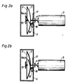
- Figs. 2a and 2b show a rotor start centering mechanism
- Fig. 3 illustrates shock protection of the oscillogyro
- Fig. 4 shows, in elevation, the gyro rotated an angle ⁇
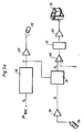
- Fig. 5a shows a block diagram of the electronic system
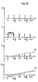
- Fig. 5b shows an associated voltage diagram
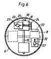
- Fig. 6 shows an end view of the oscillogyro
- Fig. 7 illustrates an alternative method of rotor detection.
- Fig. 8 shows the associated block diagram
- Fig. 9 shows i.a. an alternative gyro rotor and an alternative rotor case
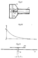
- Fig. 10 shows a curve of the step response of the rotor
- Fig. 11 shows an end view of the rotor 1.
- FIG. 1 A motor 5, motor shaft 4, leaf spring 3, torsion wire 2 an a rotor 1 constitute (with a minor exception, later to be described) an oscillogyro, which is generally conventional.
- oscillogyro For a description of the oscillogyro principles reference is made to The Journal of Mechanical Engineering Science 1967, Vol. 9, No. 1, pp 55-61,by R Whalley, M J Holgate and L Maunder, "The Oscillogyro".
- the gimbaled optical part 19 is illustrated in Fig. 1 in the form of a cylinder but it is to be understood that this optical part 19 corresponds to the stabilized part in an image-stabilized instrument.
- the appearance of this part and what optics it carries is of no consequence to the present invention. Every completely stabilized optical part in an image stabilized instrument defines an optical line-of-sight, which is found in Fig. 1 as a line 35.
- the motor 5 is secured to the casing (not shown) of the instrument and thus it follows the movements of the casing.
- a rotor 1 rotating in a plane which, on a short time basis, is inertially stabilized and thus isolated from higher frequencies of turning movements of the instrument casing about all axes orthogonal to motor shaft 4.
- the gimbaled optical part 19 is movable by way of gimbal 20 a small angle, about ⁇ 5 degrees, in relationship to the instrument casing about gimbal axes 55 and 56 and thus about all axes orthogonal to the optical line-of-sight 35 of the instrument.
- gimbal 20 does not allow part 19 to rotate about line-of-sight 35 in relation to the instrument casing.
- the gimbaled optical part 19 be mechanically locked to the instrument casing in a position where the optical line-of-sight 35 is parallel with motor shaft 4. This position is shown in Fig. 1.
- optical part 19 is disengaged but locked by way of an electromechanical control system to the angular position in the inertial space assumed by the rotational plane of rotor 1. Consequently the optical part, as the rotor, is inertially stabilized on short time basis.
- the stabilized optical part 19 should be statically balanced on its bearings.
- Rotor 1 has the form of a bar 15 having a length of the order of 40 mm. On this rotor bar two thin plates 8 and 9 are secured. Rotor 1 is secured to the thin torsion wire 2 which in turn is secured to and maintained tensioned by the bent leaf spring 3. On its central point spring 3 is secured to motor shaft 4. The case 6, containing all rotating parts, is secured to motor shaft 4. In practice rotor 1 need not have a greater moment of inertia than 1.10 ⁇ 7 kgm2, measured about the axis represented by torsion wire 2.
- Case 6 encloses all gyro components, which is desirable as otherwise the surrounding air would have a negative effect on the stability of the ultralight rotor 1 by the turbulence which would have arisen. It is obvious that the air surrounding rotor 1 within case 6 participates in the rotation and is not turbulent in any disturbing way thanks to case 6. However, case 6 should not be completely tight; a small hole 7 sees to it that there can be no pressure difference within and without case 6 to deform the case. This hole should be located as shown in Fig. 1, thus in or near the longitudinal axis of drive shaft 4, an arrangement which does not cause any air turbulence within case 6.
- case 6 does not add too much rotational inertia to the rotating parts, which would increase unnecessarily the starting time of motor 5. A low rotational inertia of case 6 will be attained if thin plastics are used.
- rotor 1 As the plane within which rotor 1 is rotating (in the following designated “rotational plane of the rotor” and indicated in Fig. 4 by dashed line RP) will behave, on a short time basis, as a free gyro rotor it will maintain its angular position in space immediately after motor 5 has slewed a small angle ⁇ about an axis orthogonal to motor shaft 4.
- rotor bar 15 is shown in that very moment of time when it is in the plane of the paper.
- the angle ⁇ between the rotational plane of the rotor and an imaginary plane P1 orthogonal to motor shaft 4 will be referred to in the following as "the angular deviation of the rotational plane".
- the rotational plane of the rotor should not, according to the invention, be inertially stabilized but travel slowly from a decentered position back to the central position perpendicular to motor shaft 4. This is accomplished by motor 5 being secured to the instrument casing at the same time as rotor 1 is dimensioned to exhibit a very low moment of inertia measured about the axis defined by wire 2. If at the same time plates 8 and 9 are suitably sized, with an area of the order of 1 square centimeter each, the viscous coupling between motor 1 and case 6 provided by the air within case 6 will have sufficient influence to bring about the desired centering of the rotational plane of the rotor.
- the precessing back to the central position described above can be utilized as a possibility of target tracking. This is a great advantage as the centering takes place spontaneously; specific precessing devices are eliminated. This constitutes a preferred embodiment of the present invention. If the design parameters are selected such that the time constant of the centering process of the rotational plane of the rotor becomes about 1 second, the rotational plane of the rotor will behave, with respect to its angular position in space, in a manner which is also very suitable to the gimbaled optical part of image-stabilized binoculars. If the casing of the binoculars is turned at a certain limited angular speed the rotational plane of the rotor will participate, at a certain lag, in this turning movement, that is, target tracking occurs.
- a purpose of the present invention is to enable in practice a larger angular deviation ⁇ , at least 5 degrees, of the rotational plane of the rotor than is possible to obtain by conventional oscillogyro mechanics.
- image-stabilized binoculars there may occur in practice rapid oscillations of the casing in relation to inertial space of at least ⁇ 5 degrees, and as motor 5 is unstabilized and thus follows the oscillations of the casing, but the rotational plane of the rotor is inertially stabilized and thus isolated from rapid oscillations, also the rotational plane RP of the rotor has to be able to assume an angular deviation ⁇ of at least the same degree in relation to the unstabilized parts (e.g. motor 5).
- this is carried out in such a way that an angular resilience is introduced between wire 2 and rotor 1.
- This angular resilience enables rotor 1 to perform small angular movements (in practice ⁇ 1 degree) in relationship to wire 2 (and thus also in relation to motor shaft 4) in the rotational plane of the rotor, thus also permitting rotor 1 to rotate at a uniform angular speed in its rotational plane.
- the simplest way in practice to introduce this angular resilience is to make the distance L (shown in Fig.
- rotor 1 should be locked in a central position, i.e. at an angle of 90 degrees to motor shaft 4, before motor 5 is started, to be freed for tilting about wire 2 only when a certain rotational speed has been reached. If this condition is not satisfied there could be, in practice, a considerable angular deviation of the rotational plane of the rotor immediately after start, which is mostly undesirable.
- Figs. 2a and 2b illustrating a possible mechanism for locking the rotor before start.
- a locking clip 16 is pivotally carried in the base 17 and can tilt a small angle in relation to said base, which is rigidly connected with motor shaft 4.
- a coiled spring 18 urges locking clip 16 towards rotor bar 15 (as shown in Fig.
- Locking clip 16 is designed such that it will then contact rotor bar 15 on either side of wire 2, rotor 1 thus being locked in a centered position and prevented from tilting about wire 2.
- motor 5 has reached a certain speed, but not full speed, after start, locking clip 16 is affected, by way of the weights 16a and 16b, by centrifugal force to tilt away from the position shown in Fig. 2a and remain in that shown in Fig. 2b, where rotor 1 is free to rock about wire 2.
- Fig. 3 where bumpers in the form in soft stops 11, 12, 13 and 14 are shown. They are secured to case 6 and limit gently the rocking movement of rotor bar 15 about wire 2 when the binoculars are panned so swiftly that the viscous air coupling between rotor 1 and case 6 does not suffice for precessing rotor 1. Stops 11-14 also receives rotor 1 at shock acceleration in a direction parallel to motor shaft 4, possibly occurring if the instrument e.g. is dropped. If the shock acceleration occurs in a direction parallell to rotor bar 15 there must also be stops, as wire 2 is rather resilient also in this direction. These stops can be formed, for example, by the inside of case 6 which the ends of rotor bar 15 may contact. For shock acceleration in a direction parallel to wire 2 no stops are needed as leaf spring 3 and wire 2 can be dimensioned sufficiently strong to assume the force. By these tricks it is gained that the complete rotor mechanism becomes very shockproof.
- motor shaft 4 should be forced, immediately upon start, to reach its proper speed as soon as possible which, if motor 5 is DC-operated, can be readily brought about by maintaining the motor 5 drive voltage on a higher than normal level immediately after start, to be then decreased to a constant, lower value when motor 5 has reached its proper speed.
- Fig. 1 The only step that remains to be taken is to lock by way of a control system the angular position of the gimbaled optical part 19 to the angular position of the rotational plane of the rotor in order to accomplish the desired stability of the gimbaled part 19.
- Two control systems have to be at hand which control the gimbaled part about two mutually perpendicular axes A1 and A2, orthogonal to the optical line-of-sight 35 of the instrument.
- control systems viz., that operating about one of the axes A1 is described in detail here, as control about the second axis (A2) is exercised in the same manner.
- An infrared light diod (LED) 22 emits short pulses of light, of the order of 100 microseconds/pulse, towards rotor 1 by way of a slot 23, which is parallel with the axis (A1) about which detection occurs.
- Case 6 has to be transparent to the infrared light where this passes the wall of the case.
- the light pulses are reflected by the plates 8 and 9 secured to rotor 1 (reflection by plate 8 is illustrated in Fig. 1), the plates being foiled and thus also acting as mirrors.
- the light Upon reflection the light finally strikes an optical zero-detector 24, whose back side is visible in Fig. 1.
- the light striking zero detector 24 is limited by slot 23 to a narrow band of a width adapted to the zero detector concerned.
- the light will also strike mirror 8 as a band 25.
- Light diode 22, slot 23 and zero detector 24 are all secured to the gimbaled optical part 19.
- a zero voltage output from zero detector 24 can only occur when the light band 25 is centered on the middle of zero detector 24 which, in turn, can only occur when part 19 and the rotational plane RP of the rotor have a certain mutual angular orientation about axis A1. This is the situation when the gimbaled optical part is "locked" by way of the control system to the rotational plane of the rotor.
- Actuator 26 can be designed optionally but it should not introduce friction.
- a possible design is shown in Fig. 1, where a wire coil 27 is secured to the instrument casing and the U--shaped permanent magnet 28 is secured to the gimbaled optical part 19. An input voltage on coil 27 then gives rise to a force tending to rotate the gimbaled part 19 about the axis concerned (A1).
- a light pulse from light diod 22 is to be emitted only at the time when case 6 and thus rotor 1 are in a position for indicating the relative angular position, about the axis concerned (A1), of optical part 19 and plane of rotation RP of the rotor. This occurs only twice per revolution, namely, when wire 2 is parallel with that axis (A1) about which the control system operates. Hence, in practice one light pulse is to be emitted when wire 2 is parallel with that axis about which the actuator 26 is able to turn optical part 19.
- U3 is conveyed to a pulse generator 50 which emits, for each positive flank of U3, a voltage pulse of a length of the order of 100 uS, a pulsating voltage U then being obtained which controls, via an exciter 53, light diod 22 so as to emit light only when voltage U is high.
- a pulse generator 50 which emits, for each positive flank of U3, a voltage pulse of a length of the order of 100 uS, a pulsating voltage U then being obtained which controls, via an exciter 53, light diod 22 so as to emit light only when voltage U is high.
- the two indications 30 and 30a shown give rise to two voltage pulses U3 and thus two light pulses per revolution. To attain one light pulse only per revolution, one of the indications should be excluded.
- the adding circuit 40 will be discussed later.
- the control device described above only operates about one single axis (A1), which is orthogonal to the line-of-sight 35 of the instrument, but as stated above it is necessary, in order to bring about a complete image-stabilizing process, to add a second similar control device to attain stabilizing about all axes orthogonal to the line-of-sight 35 of the instrument.
- this second control device operates in the same way as that described above but about an axis (A2) orthogonal to the first axis (A1), also this axis (A2) being orthogonal to the line-of-sight 35 of the instrument.
- the position of the rotor is illustrated by dashed lines in the moment of time when light diod 57 is to emit a light pulse. The light from light diod 57 passes slot 32, is reflected by the mirror 8 of the rotor and strikes finally zero detector 33.
- a second actuator capable of turning the stabilized optical part 19 about axis A2 will also be added.
- the relative position of the gimbaled part 19 (in its centered position) and the oscillogyro need not be such as shown in Fig. 1, however, it must be seen to it that the light bands from light diods 22 and 57 never miss mirrors 8 and/or 9 in operation.
- this optical part In the first place it could be desirable in certain instruments to stabilize the optical part about one axis only, orthogonal to the line-of-sight. In this case this optical part should be movable in relationship to the instrument casing about this axis only, and only one control system is then required.
- a stabilizing system according to the invention should be possible to use without prejudice together with other types of instruments or apparatus where a body is inertially stabilized on a short time basis and, on a long time basis, connected to the instrument casing.
- the gimbaled part 19 need not necessarily contain optics, a prerequisite up to now.
- case 6 can be replaced by an optional gas which, having another viscosity than the air, could create, other conditions alike, a changed viscous coupling between rotor 1 and case 6 and thus a changed time constant for precessing of the rotational plane of the rotor back to the central position perpendicular to motor shaft 4.
- an optional gas which, having another viscosity than the air, could create, other conditions alike, a changed viscous coupling between rotor 1 and case 6 and thus a changed time constant for precessing of the rotational plane of the rotor back to the central position perpendicular to motor shaft 4.
- FIG. 9 Another coupling between rotor 1 and motor shaft 4, provided optionally and operating equivalently, can replace in whole or in part the viscous effect of the air enclosed within case 6.
- leaf spring 3 is not shown.
- a pin 44 mounted on rotor bar 48 extends through a very thin and resilient diaphragm 47 into a container 45 mounted on motor shaft 49 and containing a viscous liquid 46.
- the two mirrors (8 and 9 on rotor 1) could suitably be replaced by one single mirror 43 mounted on the centre of rotor bar 48.
- Mirror 43 only couples insignificantly to the air enclosed in case 34, for which reason the viscous coupling provided by pin 44 in container 45 is required in order to render possible centering of the rotational plane of the rotor and thus target tracking.
- This also illustrates the fact that the rotor can be designed optionally within rather wide limits if only the mechanical parameters are selected such that the rotor behaves as desired.
- Case 6 which according to the foregoing description has been mounted on motor shaft 4 and thus did participate in the rotation, can be replaced if desired by a stationary housing 34, also shown in Fig. 9, mounted on the motor. However, this is not recommended as disturbances caused by air turbulence can arise.
- torsion wire 2 can be replaced by some other type of single axis bearing, for example, a conventional such bearing having crossed leaf springs.
- the gimbaled optical part 19 is designed in such a way that it has to describe, for image stability, an angular movement proportional to the angular movement of the instrument casing.
- a detection, finally producing U4 is then to take place of the mutual angle, between the gimbaled optical part and the instrument casing about the axis (A1, A2) under consideration.
- a second optionally operating detector (not shown) is adapted to give rise to a voltage U6 which is proportional to the angular position of the gimbaled optical part about axis A3 in relation to the instrument casing.
- motor 5 can be mounted relative to the instru- , ment casing by way of a soft coupling, e.g. a rubber damped coupling. This can be to advantage when it is desired to isolate the instrument casing against possible vibrations which can be transmitted from motor 5 if the rotating parts are not sufficiently balanced dynamically. This will in no way alter the function; what is essential is that motor 5 participates in the slow turning movements of the instrument casing, which makes target tracking possible.
- a soft coupling e.g. a rubber damped coupling.
- the gimbaled optical part 19 can very well be provided with a further bearing axis parallel to line-of-sight 35 to offer the possibility of turning part 19 small angles about said line 35 in relation to the instrument casing.
- the control system described above will function also in this case if only it being seen to it that the gating in of the voltage from zero detector 24 via the sample and hold circuit always takes place at the proper time, in accordance with the rule given in the foregoing.
Landscapes
- Physics & Mathematics (AREA)
- Engineering & Computer Science (AREA)
- Radar, Positioning & Navigation (AREA)
- Remote Sensing (AREA)
- General Physics & Mathematics (AREA)
- Optics & Photonics (AREA)
- Automation & Control Theory (AREA)
- Mechanical Light Control Or Optical Switches (AREA)
- Telescopes (AREA)
- Adjustment Of Camera Lenses (AREA)
- Gyroscopes (AREA)
- Control Of Position Or Direction (AREA)
- Exhaust Gas After Treatment (AREA)
- Exhaust Gas Treatment By Means Of Catalyst (AREA)
Abstract
Claims (13)
- Système de stabilisation inertielle pour un instrument, comprenant un boîtier pour l'instrument, un corps (19) monté pivotant par rapport au boîtier de l'instrument, un oscillogyro (1-6) en tant que référence de stabilité, ledit oscillogyro étant associé au boîtier de telle manière que l'axe longitudinal de l'organe d'entraînement (4) de l'oscillogyro suive sensiblement les mouvements du boîtier, des moyens de détection (22-24, 57, 32, 33) pour détecter la position angulaire du plan de rotation (RP) du rotor de l'oscillogyro, et un système de commande pour affecter la position angulaire du corps (19) monté pivotant par rapport au boîtier en accord avec la position angulaire du plan de rotation (RP) détecté.
- Un système selon la revendication 1, dans lequel le système fait partie d'un instrument optique à image stabilisée où le corps (19) monté pivotant comprend au moins une partie de l'optique de l'instrument, et en ce que le système de commande affecte le corps (19) monté pivotant de telle manière que le corps soit, autour d'au moins un axe (A1 ; A2) et par rapport à sa position angulaire, stabilisé de manière inertielle ou décrive des mouvements angulaires proportionnels mais séparés des mouvements angulaires du boîtier de l'instrument.
- Un système selon la revendication 1 ou 2, dans lequel le rotor (1) et l'organe d'entraînement (4) de l'oscillogyro sont montés de manière mutuellement élastique de façon à permettre de petits mouvements angulaires mutuels entre le rotor (1) et l'organe d'entraînement (4) de l'oscillogyro sensiblement dans un plan orthogonal à l'axe longitudinal de l'organe d'entraînement (4) de l'oscillogyro afin d'augmenter considérablement la stabilité du plan de rotation (RP) de l'oscillogyro aux déviations angulaires (α) plus importantes du plan de rotation (RP).
- Un système selon la revendication 1, 2 ou 3, dans lequel le rotor (1) de l'oscillogyro est situé à l'intérieur d'une boîte (6 ; 34) et en ce qu'il existe une liaison entre le rotor (1) et l'organe d'entraînement (4) introduisant un moment entre le rotor (1) et l'organe d'entraînement (4) autour d'un palier d'axe unique (2) de l'oscillogyro, ledit moment étant sensiblement proportionnel à la vitesse angulaire relative du rotor (1) et de l'organe d'entraînement (4) autour dudit palier d'axe unique (2) de l'oscillogyro, ladite liaison permettant un changement angulaire intentionnel du plan de rotation (RP) et ainsi, par l'intermédiaire dudit système de commande, un changement angulaire du corps (19) monté pivotant, par exemple, dans le suivi ou le panoramiquage d'une cible.
- Un système selon la revendication 4, dans lequel de l'air ou un autre gaz à l'intérieur de ladite boîte (6 ; 34) crée au moins la plus grande partie de la liaison entre le rotor (1) et l'organe d'entraînement (4) de l'oscillogyro.
- Un système selon la revendication 4, dans lequel ledit système de commande est prévu pour maintenir une orientation angulaire mutuelle constante entre le plan de rotation (RP) du rotor et le corps monté pivotant, au moins autour d'un axe (A1).
- Un système selon la revendication 4, dans lequel la boîte (6) est prévue pour participer à la rotation de l'organe d'entraînement (4) de l'oscillogyro et la suivre.
- Un système selon la revendication 4 ou 5, dans lequel le palier d'axe unique de l'oscillogyro comprend un fil de torsion sous tension (2) qui est fixé de chaque côté du rotor, la distance entre les points de fixation étant suffisamment petite pour produire ladite résilience angulaire entre le rotor et l'organe d'entraînement de l'oscillogyro.
- Un système selon la revendication 8, dans lequel la possibilité pour le rotor (1) de se déplacer dans la direction radiale du fil de torsion (2) est limitée par des butées (11-14).
- Un système selon la revendication 4, dans lequel un élément (16) est prévu, lorsque l'organe d'entraînement (4) est au repos, pour venir élastiquement en prise avec le rotor (1) et ainsi verrouiller le rotor dans une position centrée et en ce que, après le départ de l'oscillogyro, ledit élément (16) libère le rotor selon un nombre de tours par minute prédéterminé par action de la force centrifuge.
- Un système selon les revendications 1 à 10, dans lequel les moyens de détection comprennent au moins une diode lumineuse (22) et un détecteur de zéro (24), la diode lumineuse émettant de courtes impulsions de lumière qui sont réfléchies par au moins une surface réfléchissante (8, 9) sur le rotor pour alors frapper le détecteur (24).
- Un système selon la revendication 11, dans lequel le signal de sortie (U1 ; U8) du détecteur (24 ; 36) est relié à un circuit d'échantillonnage et de maintien (31) dont le signal de sortie est filtré en fréquence et appliqué à un actionneur (26) qui est prévu pour affecter la position angulaire du corps monté pivotant (19).
- Un système selon la revendication 1, dans lequel ledit organe d'entraînement (4) entraîne le rotor (1) par l'intermédiaire d'un palier d'axe unique (2) pour tourner autour dudit axe longitudinal selon un nombre de tours par minute sensiblement constant, en ce que l'axe longitudinal de l'organe d'entraînement (4) participe aux mouvements angulaires de basse fréquence du boîtier par rapport à un espace inertiel, en ce que le rotor (1) est situé à l'intérieur d'une boîte (6 ; 34) où de l'air ou un autre gaz à l'intérieur de la boîte participe principalement à la rotation de l'organe d'entraînement, en ce qu'il existe entre le rotor (1) et l'organe d'entraînement (4) une liaison introduisant entre le rotor (1) et l'organe d'entraînement (4) un moment sensiblement proportionnel à la vitesse angulaire relative du rotor (1) et de l'organe d'entraînement (4) autour du palier d'axe unique (2), en ce qu'un centrage du plan de rotation (RP) du rotor se produit sur une longue base de temps du fait du déplacement angulaire dans l'espace inertiel auquel le plan de rotation (RP), du fait de ladite liaison, est soumis à une déviation angulaire (α), et en ce qu'une augmentation sensible de la stabilité du plan de rotation par rapport à l'espace inertiel est obtenue sur un intervalle angulaire de la déviation angulaire (α) par la caractéristique qu'une résilience angulaire est prévue pour rendre possibles des mouvements angulaires mutuels, suffisamment importants à cet effet, entre le rotor (1) et l'organe d'entraînement (4) de l'oscillogyro dans le plan (RP) dans lequel tourne le rotor (1).
Applications Claiming Priority (3)
| Application Number | Priority Date | Filing Date | Title |
|---|---|---|---|
| SE8902806A SE467378B (sv) | 1989-08-23 | 1989-08-23 | Troeghetsstabiliseringssystem foer ett instrument |
| SE8902806 | 1989-08-23 | ||
| PCT/SE1990/000539 WO1991002997A1 (fr) | 1989-08-23 | 1990-08-21 | Systeme de stabilisation inertielle |
Publications (2)
| Publication Number | Publication Date |
|---|---|
| EP0487622A1 EP0487622A1 (fr) | 1992-06-03 |
| EP0487622B1 true EP0487622B1 (fr) | 1995-04-05 |
Family
ID=20376723
Family Applications (1)
| Application Number | Title | Priority Date | Filing Date |
|---|---|---|---|
| EP90913263A Expired - Lifetime EP0487622B1 (fr) | 1989-08-23 | 1990-08-21 | Systeme de stabilisation inertielle |
Country Status (7)
| Country | Link |
|---|---|
| US (1) | US5237450A (fr) |
| EP (1) | EP0487622B1 (fr) |
| JP (1) | JPH05500867A (fr) |
| AU (1) | AU6346790A (fr) |
| DE (1) | DE69018472T2 (fr) |
| SE (1) | SE467378B (fr) |
| WO (1) | WO1991002997A1 (fr) |
Cited By (1)
| Publication number | Priority date | Publication date | Assignee | Title |
|---|---|---|---|---|
| CN104154910A (zh) * | 2014-07-22 | 2014-11-19 | 清华大学 | 一种微型无人机室内定位方法 |
Families Citing this family (18)
| Publication number | Priority date | Publication date | Assignee | Title |
|---|---|---|---|---|
| US5825545A (en) * | 1992-09-21 | 1998-10-20 | Canon Kabushiki Kaisha | Image stabilizing device |
| CH687108A5 (de) * | 1992-12-24 | 1996-09-13 | Anschuetz & Co Gmbh | Bildstabilisierungseinrichtung. |
| SE9603716L (sv) * | 1996-10-11 | 1998-04-06 | Polytech Ab | Anordning för stabilisering av fjärrstyrd sensor, såsom kamera |
| US6046824A (en) * | 1997-02-06 | 2000-04-04 | Nice Systems, Ltd. | Facsimile long term storage and retrieval system |
| US6067194A (en) * | 1997-09-29 | 2000-05-23 | Leica Camera Ag | Image stabilizing instrument |
| AU2003278834A1 (en) * | 2002-09-18 | 2004-04-08 | Incucomm, Inc. | Control processor for use with a transceiver in an optical wireless network |
| US7404324B2 (en) * | 2005-08-19 | 2008-07-29 | Honeywell International Inc. | Gunhard shock isolation system |
| US7846131B2 (en) * | 2005-09-30 | 2010-12-07 | Covidien Ag | Administration feeding set and flow control apparatus with secure loading features |
| US7763005B2 (en) * | 2006-03-02 | 2010-07-27 | Covidien Ag | Method for using a pump set having secure loading features |
| US7722573B2 (en) * | 2006-03-02 | 2010-05-25 | Covidien Ag | Pumping apparatus with secure loading features |
| US7722562B2 (en) * | 2006-03-02 | 2010-05-25 | Tyco Healthcare Group Lp | Pump set with safety interlock |
| US7927304B2 (en) | 2006-03-02 | 2011-04-19 | Tyco Healthcare Group Lp | Enteral feeding pump and feeding set therefor |
| US7758551B2 (en) * | 2006-03-02 | 2010-07-20 | Covidien Ag | Pump set with secure loading features |
| US8021336B2 (en) | 2007-01-05 | 2011-09-20 | Tyco Healthcare Group Lp | Pump set for administering fluid with secure loading features and manufacture of component therefor |
| US7560686B2 (en) | 2006-12-11 | 2009-07-14 | Tyco Healthcare Group Lp | Pump set and pump with electromagnetic radiation operated interlock |
| US20080147008A1 (en) * | 2006-12-15 | 2008-06-19 | Tyco Healthcare Group Lp | Optical detection of medical pump rotor position |
| US8154274B2 (en) | 2010-05-11 | 2012-04-10 | Tyco Healthcare Group Lp | Safety interlock |
| CN116086421B (zh) * | 2023-02-14 | 2025-07-18 | 瑞声开泰科技(武汉)有限公司 | 一种微机械陀螺仪及电子产品 |
Family Cites Families (9)
| Publication number | Priority date | Publication date | Assignee | Title |
|---|---|---|---|---|
| US2688456A (en) * | 1949-08-16 | 1954-09-07 | Jensen Homer | Stabilizing system |
| US3591250A (en) * | 1968-04-08 | 1971-07-06 | Stek Corp | Mechanical image motion stabilizer with rotation rate comparison system |
| US3564931A (en) * | 1968-09-04 | 1971-02-23 | Optigon Res & Dev Corp | Nutational motion damping means for gyroscopic apparatus |
| US3756686A (en) * | 1971-09-08 | 1973-09-04 | Optigon Res & Dev Corp | Servo-integrating stabilizer |
| US4662727A (en) * | 1983-08-01 | 1987-05-05 | Hughes Aircraft Company | Two-axis optical inertial system using a gyro rotor as a stable reference |
| GB2149259B (en) * | 1983-11-04 | 1987-08-05 | Ferranti Plc | Improvements relating to sightline stabilising apparatus |
| JPS60143330A (ja) * | 1983-12-29 | 1985-07-29 | Matsushita Electric Ind Co Ltd | 撮影装置 |
| US4701602A (en) * | 1984-08-02 | 1987-10-20 | Hughes Aircraft Company | Adaptable modular stabilization system |
| FR2624989B1 (fr) * | 1987-12-17 | 1991-08-09 | Aerospatiale | Dispositif inertiel de stabilisation en inclinaison d'un element orientable et miroir de telescope embarque muni d'un tel dispositif |
-
1989
- 1989-08-23 SE SE8902806A patent/SE467378B/sv not_active IP Right Cessation
-
1990
- 1990-08-21 EP EP90913263A patent/EP0487622B1/fr not_active Expired - Lifetime
- 1990-08-21 AU AU63467/90A patent/AU6346790A/en not_active Abandoned
- 1990-08-21 WO PCT/SE1990/000539 patent/WO1991002997A1/fr not_active Ceased
- 1990-08-21 US US07/836,001 patent/US5237450A/en not_active Expired - Fee Related
- 1990-08-21 DE DE69018472T patent/DE69018472T2/de not_active Expired - Fee Related
- 1990-08-21 JP JP2512449A patent/JPH05500867A/ja active Pending
Cited By (1)
| Publication number | Priority date | Publication date | Assignee | Title |
|---|---|---|---|---|
| CN104154910A (zh) * | 2014-07-22 | 2014-11-19 | 清华大学 | 一种微型无人机室内定位方法 |
Also Published As
| Publication number | Publication date |
|---|---|
| EP0487622A1 (fr) | 1992-06-03 |
| AU6346790A (en) | 1991-04-03 |
| DE69018472D1 (de) | 1995-05-11 |
| SE467378B (sv) | 1992-07-06 |
| JPH05500867A (ja) | 1993-02-18 |
| SE8902806D0 (sv) | 1989-08-23 |
| US5237450A (en) | 1993-08-17 |
| DE69018472T2 (de) | 1995-12-07 |
| WO1991002997A1 (fr) | 1991-03-07 |
| SE8902806L (sv) | 1991-02-24 |
Similar Documents
| Publication | Publication Date | Title |
|---|---|---|
| US5237450A (en) | Inertial stabilizing system | |
| US5897223A (en) | Stabilized platform system for camera | |
| US4465346A (en) | Optically stabilized telescope | |
| US4315610A (en) | Optical image stabilizing system | |
| US20010012155A1 (en) | Optical apparatus | |
| US5798863A (en) | Image stabilized optical system | |
| US8079258B1 (en) | Gyroscope and pendulous gyroscopic accelerometer with adjustable scale factor, and gravity gradiometer using such | |
| KR900000322B1 (ko) | 안정한 기준으로서 자이로 회전자를 사용하는 2-축 광학 관성 시스템 | |
| US4636700A (en) | Position servo system | |
| US4096427A (en) | Nutation damping in dual-spin stabilized devices | |
| US3503663A (en) | Gyroscopically controlled motion compensator for optical devices | |
| US6338274B1 (en) | Tuned flexure accelerometer | |
| US3892467A (en) | Inertial stabilization system | |
| US3888562A (en) | Oscillating scanner | |
| US3967178A (en) | Wide band angular displacement and velocity sensor and method | |
| US3756686A (en) | Servo-integrating stabilizer | |
| US2855781A (en) | Stable reference platform | |
| US3818767A (en) | Passive dual-spin misalignment compensators | |
| US5027047A (en) | Half angle mechanism for a heliostat | |
| US4675688A (en) | Rate sensor with coaxially mounted scanning antenna | |
| RU2101742C1 (ru) | Оптико-электронный следящий координатор | |
| KR960700538A (ko) | 레이다 장치(Radar apparatus) | |
| Tokovinin | Pendular seismometer for correcting telescope vibrations | |
| US4340271A (en) | Internal body mounted system for isolation of, in one degree of freedom, a beam projected from an optical system which is subject to rotational vibration | |
| IL103644A (en) | Apparatus for measuring the rate of rotation and linear acceleration of a moving body in two perpendicular axes |
Legal Events
| Date | Code | Title | Description |
|---|---|---|---|
| PUAI | Public reference made under article 153(3) epc to a published international application that has entered the european phase |
Free format text: ORIGINAL CODE: 0009012 |
|
| 17P | Request for examination filed |
Effective date: 19920206 |
|
| AK | Designated contracting states |
Kind code of ref document: A1 Designated state(s): BE DE FR GB IT NL |
|
| 17Q | First examination report despatched |
Effective date: 19931209 |
|
| GRAA | (expected) grant |
Free format text: ORIGINAL CODE: 0009210 |
|
| AK | Designated contracting states |
Kind code of ref document: B1 Designated state(s): BE DE FR GB IT NL |
|
| PG25 | Lapsed in a contracting state [announced via postgrant information from national office to epo] |
Ref country code: IT Free format text: LAPSE BECAUSE OF FAILURE TO SUBMIT A TRANSLATION OF THE DESCRIPTION OR TO PAY THE FEE WITHIN THE PRE;WARNING: LAPSES OF ITALIAN PATENTS WITH EFFECTIVE DATE BEFORE 2007 MAY HAVE OCCURRED AT ANY TIME BEFORE 2007. THE CORRECT EFFECTIVE DATE MAY BE DIFFERENT FROM THE ONE RECORDED.SCRIBED TIME-LIMIT Effective date: 19950405 Ref country code: BE Effective date: 19950405 Ref country code: NL Free format text: LAPSE BECAUSE OF NON-PAYMENT OF DUE FEES Effective date: 19950405 Ref country code: FR Effective date: 19950405 |
|
| REF | Corresponds to: |
Ref document number: 69018472 Country of ref document: DE Date of ref document: 19950511 |
|
| EN | Fr: translation not filed | ||
| NLV1 | Nl: lapsed or annulled due to failure to fulfill the requirements of art. 29p and 29m of the patents act | ||
| PLBE | No opposition filed within time limit |
Free format text: ORIGINAL CODE: 0009261 |
|
| STAA | Information on the status of an ep patent application or granted ep patent |
Free format text: STATUS: NO OPPOSITION FILED WITHIN TIME LIMIT |
|
| 26N | No opposition filed | ||
| PGFP | Annual fee paid to national office [announced via postgrant information from national office to epo] |
Ref country code: DE Payment date: 19980817 Year of fee payment: 9 |
|
| PGFP | Annual fee paid to national office [announced via postgrant information from national office to epo] |
Ref country code: GB Payment date: 19990728 Year of fee payment: 10 |
|
| PG25 | Lapsed in a contracting state [announced via postgrant information from national office to epo] |
Ref country code: DE Free format text: LAPSE BECAUSE OF NON-PAYMENT OF DUE FEES Effective date: 20000601 |
|
| PG25 | Lapsed in a contracting state [announced via postgrant information from national office to epo] |
Ref country code: GB Free format text: LAPSE BECAUSE OF NON-PAYMENT OF DUE FEES Effective date: 20000821 |
|
| GBPC | Gb: european patent ceased through non-payment of renewal fee |
Effective date: 20000821 |