EP0487671B1 - Haltevorrichtung für batterien - Google Patents
Haltevorrichtung für batterien Download PDFInfo
- Publication number
- EP0487671B1 EP0487671B1 EP91910710A EP91910710A EP0487671B1 EP 0487671 B1 EP0487671 B1 EP 0487671B1 EP 91910710 A EP91910710 A EP 91910710A EP 91910710 A EP91910710 A EP 91910710A EP 0487671 B1 EP0487671 B1 EP 0487671B1
- Authority
- EP
- European Patent Office
- Prior art keywords
- pair
- batteries
- bracket member
- mounting apparatus
- set forth
- Prior art date
- Legal status (The legal status is an assumption and is not a legal conclusion. Google has not performed a legal analysis and makes no representation as to the accuracy of the status listed.)
- Expired - Lifetime
Links
- 230000003014 reinforcing effect Effects 0.000 claims description 8
- 238000010276 construction Methods 0.000 claims description 3
- 230000002093 peripheral effect Effects 0.000 claims description 2
- 239000002184 metal Substances 0.000 description 6
- 230000005611 electricity Effects 0.000 description 3
- QAOWNCQODCNURD-UHFFFAOYSA-N Sulfuric acid Chemical compound OS(O)(=O)=O QAOWNCQODCNURD-UHFFFAOYSA-N 0.000 description 2
- 230000007797 corrosion Effects 0.000 description 2
- 238000005260 corrosion Methods 0.000 description 2
- 238000000034 method Methods 0.000 description 2
- 208000032953 Device battery issue Diseases 0.000 description 1
- 239000004020 conductor Substances 0.000 description 1
- 238000005336 cracking Methods 0.000 description 1
- 230000002939 deleterious effect Effects 0.000 description 1
- 238000009826 distribution Methods 0.000 description 1
- 239000007788 liquid Substances 0.000 description 1
- 238000012423 maintenance Methods 0.000 description 1
- 239000000463 material Substances 0.000 description 1
- 230000000284 resting effect Effects 0.000 description 1
- 230000035939 shock Effects 0.000 description 1
- 238000003860 storage Methods 0.000 description 1
- 238000003466 welding Methods 0.000 description 1
Images

Classifications
-
- B—PERFORMING OPERATIONS; TRANSPORTING
- B60—VEHICLES IN GENERAL
- B60K—ARRANGEMENT OR MOUNTING OF PROPULSION UNITS OR OF TRANSMISSIONS IN VEHICLES; ARRANGEMENT OR MOUNTING OF PLURAL DIVERSE PRIME-MOVERS IN VEHICLES; AUXILIARY DRIVES FOR VEHICLES; INSTRUMENTATION OR DASHBOARDS FOR VEHICLES; ARRANGEMENTS IN CONNECTION WITH COOLING, AIR INTAKE, GAS EXHAUST OR FUEL SUPPLY OF PROPULSION UNITS IN VEHICLES
- B60K1/00—Arrangement or mounting of electrical propulsion units
- B60K1/04—Arrangement or mounting of electrical propulsion units of the electric storage means for propulsion
-
- B—PERFORMING OPERATIONS; TRANSPORTING
- B60—VEHICLES IN GENERAL
- B60R—VEHICLES, VEHICLE FITTINGS, OR VEHICLE PARTS, NOT OTHERWISE PROVIDED FOR
- B60R16/00—Electric or fluid circuits specially adapted for vehicles and not otherwise provided for; Arrangement of elements of electric or fluid circuits specially adapted for vehicles and not otherwise provided for
- B60R16/02—Electric or fluid circuits specially adapted for vehicles and not otherwise provided for; Arrangement of elements of electric or fluid circuits specially adapted for vehicles and not otherwise provided for electric constitutive elements
- B60R16/04—Arrangement of batteries
-
- H—ELECTRICITY
- H01—ELECTRIC ELEMENTS
- H01M—PROCESSES OR MEANS, e.g. BATTERIES, FOR THE DIRECT CONVERSION OF CHEMICAL ENERGY INTO ELECTRICAL ENERGY
- H01M50/00—Constructional details or processes of manufacture of the non-active parts of electrochemical cells other than fuel cells, e.g. hybrid cells
- H01M50/20—Mountings; Secondary casings or frames; Racks, modules or packs; Suspension devices; Shock absorbers; Transport or carrying devices; Holders
- H01M50/204—Racks, modules or packs for multiple batteries or multiple cells
- H01M50/207—Racks, modules or packs for multiple batteries or multiple cells characterised by their shape
- H01M50/209—Racks, modules or packs for multiple batteries or multiple cells characterised by their shape adapted for prismatic or rectangular cells
-
- H—ELECTRICITY
- H01—ELECTRIC ELEMENTS
- H01M—PROCESSES OR MEANS, e.g. BATTERIES, FOR THE DIRECT CONVERSION OF CHEMICAL ENERGY INTO ELECTRICAL ENERGY
- H01M50/00—Constructional details or processes of manufacture of the non-active parts of electrochemical cells other than fuel cells, e.g. hybrid cells
- H01M50/20—Mountings; Secondary casings or frames; Racks, modules or packs; Suspension devices; Shock absorbers; Transport or carrying devices; Holders
- H01M50/244—Secondary casings; Racks; Suspension devices; Carrying devices; Holders characterised by their mounting method
-
- H—ELECTRICITY
- H01—ELECTRIC ELEMENTS
- H01M—PROCESSES OR MEANS, e.g. BATTERIES, FOR THE DIRECT CONVERSION OF CHEMICAL ENERGY INTO ELECTRICAL ENERGY
- H01M50/00—Constructional details or processes of manufacture of the non-active parts of electrochemical cells other than fuel cells, e.g. hybrid cells
- H01M50/20—Mountings; Secondary casings or frames; Racks, modules or packs; Suspension devices; Shock absorbers; Transport or carrying devices; Holders
- H01M50/262—Mountings; Secondary casings or frames; Racks, modules or packs; Suspension devices; Shock absorbers; Transport or carrying devices; Holders with fastening means, e.g. locks
-
- Y—GENERAL TAGGING OF NEW TECHNOLOGICAL DEVELOPMENTS; GENERAL TAGGING OF CROSS-SECTIONAL TECHNOLOGIES SPANNING OVER SEVERAL SECTIONS OF THE IPC; TECHNICAL SUBJECTS COVERED BY FORMER USPC CROSS-REFERENCE ART COLLECTIONS [XRACs] AND DIGESTS
- Y02—TECHNOLOGIES OR APPLICATIONS FOR MITIGATION OR ADAPTATION AGAINST CLIMATE CHANGE
- Y02E—REDUCTION OF GREENHOUSE GAS [GHG] EMISSIONS, RELATED TO ENERGY GENERATION, TRANSMISSION OR DISTRIBUTION
- Y02E60/00—Enabling technologies; Technologies with a potential or indirect contribution to GHG emissions mitigation
- Y02E60/10—Energy storage using batteries
Definitions
- This invention relates generally to a mounting apparatus and more particularly to a mounting apparatus for one or more batteries.
- a typical mounting for a pair of batteries includes a metal frame member that rests on top of the batteries as they rest in place on a base plate.
- the frame typically surrounds the outer extremities of the battery and is secured to the base plate by numerous threaded fasteners that extend between the frame and the base plate.
- fasteners are spaced from each other at each end of the assembly to provide a clamping force against the batteries to hold them in place.
- US-A-3,894,607 Another type of mounting for a battery is disclosed in US-A-3,894,607.
- the fastening means includes a nut that engages a threaded rod that extends upwardly between the two batteries.
- a pair of bearing members extend between the nut and the inner edges of the batteries to transmit and spread the torque of the nut along a substantial length of the batteries. While this mounting structure is simple in design, it must be noted that the battery terminals and associated cable clamps are left exposed to the environment. This can be a problem especially in an engine compartment wherein the use of various tools are required for repair and maintenance. Since the pair of batteries are mounted in side-by-side relation to each other, they form a natural shelf.
- the present invention is directed to overcoming one or more of the problems as set forth above by providing a mounting apparatus as set forth in claims 1 and 12.
- a mounting apparatus for at least one battery includes a base and a bracket member that has a plurality of engagement surfaces formed thereon.
- a means for mounting the bracket member to the base is provided and is utilized to secure the position of the battery.
- the mounting means is structured to urge the bracket means between a first position wherein the engagement surfaces are generally concave and a second position wherein the engagement surfaces are substantially flat and are fully engaged with the battery.
- one or more batteries may be mounted to a vehicle or the like in a very simple and effective manner. Since the mounting bracket is provided with engagement surfaces that are concave in their free state, they tend to flatten upon loading. In doing so, the load from the mounting means is spread out over the entire area of contact between the bracket member and the battery. Localized loading of the battery casing by the mounting means is thus avoided and the possibility of fracture of the battery case is greatly reduced.
- a mounting apparatus for a pair of batteries includes a base for supporting the batteries in side-by-side relation to each other such that the batteries define inner and outer longitudinally directed engagement surfaces on the upper surface of each battery.
- a bracket member is provided that has a centrally disposed aperture extending through it and further defines a plurality of longitudinally directed, generally concave, engagement surfaces. The bracket member is positionable on the batteries with its engagement surfaces adjacent the engagement surfaces defined by the batteries.
- a threaded rod member is connected to the base and extends upwardly therefrom so as to be positioned between the batteries.
- a fastening means is provided that is engageable with the threaded rod member and an upper surface of the bracket member.
- the fastening means is rotatable with respect to the threaded rod member and serves to affect the movement of the bracket member between a first and second position. In the first position, a peripheral portion of the engagement surfaces of the bracket member is in contact with the engagement surfaces of the batteries, while in the second position the engagement surfaces of the bracket member and the batteries are in full engagement with each other.
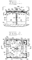
- a mounting apparatus for mounting a pair of batteries 12 and 14.
- the batteries 12 and 14 rest in side-by-side relation on a base on frame 16.
- the batteries each define an inner sidewall 18 and 20 that face each other when the batteries are mounted to the base 16 and an outer sidewall 22 and 24.
- each battery defines a pair of end walls 26, 28, 30 and 32 respectively.
- Battery terminals 34, 36, 38 and 40 extend from a top surface 42 and 44 of the respective batteries 12 and 14. Since the batteries are connected in series, a first cable 46 extends between the terminals 36 and 40 of the batteries and is secured to each terminal by a clamping device 48 of a well-known design.
- a second cable 50 (Fig. 2) is attached to the terminal 34 of battery 12 by a clamp 48 and communicates electricity with the various vehicle systems (not shown).
- a third cable 52 is attached to the terminal 38 of battery 14 by another clamp 48 and is in turn connected to a suitable ground (not shown).
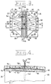
- a bracket member 54 is placed in overlying relation to the upper surfaces 42 and 44 of each battery 12 and 14. As is best shown in Fig. 3, the bracket is generally cross-shaped in configuration and defines a first pair of arms 56 and 58 that extend in a first or longitudinal direction with respect to the batteries. A second pair of arms 60 and 62 is defined by the bracket and extends in a second, lateral direction that is normal to the first. Each arm defines a vertically oriented flange 64, 66, 68 and 70.
- Flanges 64 and 66 extend downwardly from the first pair of arms 56 and 58 to engage the end walls 26, 30, 28, 32 of the respective batteries, while flanges 68 and 70 extend downwardly from the second pair of arms 60 and 62 to engage the respective outer walls 22 and 24 of the respective batteries 12 and 14.
- a recess or cutout 72 Positioned between each arm is a recess or cutout 72 that receives one of the respective battery terminals 34, 36, 38 and 40 when the bracket is positioned on top of the batteries.
- a first plurality of reinforcing ribs 74 are integrally formed along the longitudinal centerline of the bracket member 54 and extend the length between the first pair of arms 56 and 58 (Fig. 3).
- the ribs form a plurality of upwardly open channels 76 that serve to strengthen the bracket in the longitudinal direction and to evenly transfer force as will be described hereinafter.
- a first pair of engagement surfaces 78 and 80 are positioned on a lower surface 82 of the channels.
- the engagement surfaces 78 and 80 are spaced from each other on opposite sides of the longitudinal centerline (X) and extend the full distance between the first pair of arms 56 and 58.
- a downwardly open channel 84 is formed between the engagement surfaces 78 and 80.
- the channel further defines an extension or locating rib 86 and 88 that protrudes downwardly beyond the respective engagement surfaces 78 and 80 and is joined therewith.
- the locating ribs 86 and 88 are positioned between the batteries 12 and 14 when the bracket is mounted thereon and are engageable with the inner sidewalls 18 and 20 of the batteries to properly locate and align the assembly.
- a second pair of engagement surfaces 90 and 92 are formed on the bracket member 54 and are positioned in inwardly adjacent relation to the vertically oriented flanges 68 and 70 of the second pair of arms 60 and 62 respectively. All of the engagement surfaces 78, 80, 90 and 92 are oriented in parallel relation to the longitudinal centerline (x) of the bracket member 54. As is best shown in Fig.
- the first pair of engagement surfaces 78 and 80 are generally arcuate or concave in configuration when the bracket is in an unassembled condition.
- the second pair of engagement surfaces 90 and 92 is also concave in configuration as can best be seen in Fig. 5.
- the arc or concavity defined by the second pair of engagement surfaces 90 and 92 extends in a direction that is normal to that of the first pair.
- the first pair of engagement surfaces 78 and 80 are positioned vertically above the second pair of engagement surfaces 90 and 92. While being substantially flat in this plane the first pair of engagement surfaces are located generally along a projected arc defined by the second pair of engagement surfaces.
- a second plurality of reinforcing ribs 94 are integrally formed in the bracket member 54 and extend between the second pair of arms 60 and 62. These reinforcing ribs 94 are positioned at an angle with respect to both pairs of arms and generally diagonally oriented with respect to arms 60 and 62 (Fig. 3).
- An aperture 96 is formed through the bracket member 54 and is located within the channel 84 formed by the first plurality of reinforcing ribs at the center of the bracket member.
- a cover member 98 is provided to be mounted on top of the bracket member 54 in overlying relation to the bracket member and the battery terminals 34, 36, 38 and 40 as can be seen in Figs.1, 2 and 6.
- the cover is generally rectangular in configuration and forms a plurality of wing members 100 at each corner.
- a downwardly extending lip 102 borders each wing member 100 for at least a portion of the outer periphery thereof. The border is non-continuous to provide openings 104 that receive the respective battery cables 46, 50 and 52 when the cover member is mounted in place.
- the bordering lip 102 provides a certain amount of stiffness to allow it to support an ample amount of weight without collapsing while at the same time allowing the cover to be relatively deformable without cracking.
- the bordering lip 102 extends around the periphery of the wings 100 a distance sufficient to border at least a portion of a pair of recesses 106 and 108 defined on opposite sides 110 and 112 of the cover member 98.
- a pair of extensions 114 and 116 of the lip 102 border the recess 106 and engage opposing sides 118 and 120 of arm 60.
- Another pair of extensions 122 and 124 of the lip 102 border the recess 108 and engage opposite sides 126 and 128 of arm 62.
- the cover member 98 defines a central portion that includes a plurality of concentric annular portions (Fig. 6).
- a first portion 130 is engaged with an upper surface 132 of the bracket member 54 and provides rigidity to the cover in the central portion thereof.
- a second annular portion 134 is raised slightly from the first and has a diameter that is slightly less than that of the first annular portion 130.
- a third annular portion 136 extends upwardly from the second annular portion 134 and has a diameter reduced from that of the second annular portion.
- An aperture 138 is formed through the cover 98 and opens onto the third annular portion 136. The aperture is centered with respect to the concentric annular portions and the overall cover member itself.
- a mounting means 139 engages both the cover member 98 and the bracket 54 to secure them to the base 16.
- a rod member 140 is secured to the base 16 by any one of several well known methods such as welding (Fig. 1).
- the rod is threaded along a distal portion 142 thereof and is centrally located with respect to the base 16.
- the rod 140 is located so as to extend upwardly from the base to a position between batteries 12 and 14.
- the rod sufficiently sized to be received within the aperture 96 of the bracket member 54.
- a first fastening means 144 is threadably engageable with the rod member 140 and bears against a washer 146 that is positioned about the rod and rests upon the upper surface 132 of the bracket member 54.
- the first fastening means 144 is in the form of a common threaded nut and serves to secure the bracket member 54 to the base 16.
- the rod member 140 is also sufficiently sized to be received within the aperture 138 of the cover member 98.
- a second fastening means in the form of a wing nut 148 is also threadably engaged with the rod member 140. The wing nut 148 bears against an upper surface 150 of the cover member 98 to capture the cover member between the first and second fastening means 144 and 148 to secure the cover member 98 to the bracket member 54 and complete the assembly.
- the batteries 12 and 14 When it is desirable to mount the batteries 12 and 14 to the base 16, they are positioned on the base with the rod member 140 extending upwardly between the inner sidewalls 18 and 20 of the batteries.
- the bracket member 54 is placed on top of the batteries with the rod member 140 extending through the aperture 96 in the bracket.
- the bracket is positioned on the top surface 42 and 44 of the batteries so that the locating ribs 86 and 88 extend down between the batteries so as to engage the respective inner sidewalls 18 and 20 of the batteries.
- the vertically oriented flanges 64, 66, 68 and 70 defined by the respective arms 56, 58, 60 and 62 are engaged with the outer extremities of the batteries.
- the batteries are held from relative movement in a longitudinal direction through engagement with flanges 64 and 66.
- Flange 64 engages the aligned end walls 26 and 30 of the batteries 12 and 14 while flange 66 engages the aligned end walls 28 and 32.
- Relative movement in a lateral direction is prevented by flanges 68 and 70 which engage the respective outer sidewalls 22 and 24.
- the engagement surfaces 78 and 80 are in their unassembled, concave position and are only in contact with the batteries in the area adjacent flanges 64 and 66. Similarly, it can be seen when viewing Fig.
- the cover member 98 may be fastened in place.
- the cover 98 is then positioned over the bracket member 54 with the rod member 140 extending through the aperture 138.
- the cover is positioned with respect to the bracket member so that the recesses 106 and 108 are placed over the respective arms 60 and 62 of the bracket member.
- the extensions 114 and 116 of the lip 102 are brought into engagement with the respective sides 118 and 120 of arm 60 while the extensions 122 and 124 of lip 102 are engaged with sides 126 and 128 of arm 62. In this position, the wing members 100 are placed in overlying relation to the respective terminals 34, 36, 38 and 40.
- first annular portion 130 will be placed in resting engagement with the upper surface 132 of the bracket member 54.
- the second annular portion 134 is upraised from the surface of the bracket member an amount to accommodate the thickness of the washer 146.
- the third annular portion 136 is upraised from the second annular portion 134 an amount sufficient to accommodate the nut 144.
- the wing nut 148 is then threaded onto the rod member 140 until it contacts the cover member 98 to sandwich the cover member against the nut 144.
- the mounting apparatus 10 as set forth above provides a mechanism for securing a pair of batteries 12 and 14 to a base 16 in a manner that is accomplished in a quick and easy manner with a minimum of hardware. Because of the concavity of the engagement surfaces 78, 80, 90 and 92, the entire force from the single fastening means 144 for the bracket member 54 is evenly distributed over the upper surfaces 42 and 44 of each battery. This force distribution is aided by the reinforcing ribs 74 and 94 that are integrally formed in the bracket member 54. A uniform transfer of force created by the torque of the nut 144 prevents a concentration of force on one portion of the battery casing which could otherwise cause the casing to fracture.
- the subject mounting apparatus 10 also provides an optional cover 98 for the battery terminals 34, 36, 38 and 40 and their associated clamping hardware 48.
- the cover provides a safe place for tools to be temporarily placed without risk of damaging the terminals through incidental contact with the tools or through cross-connection between the terminals and subsequent inadvertent discharge of the batteries.
- the cover also protects the terminals and associated clamps from any inadvertent spillage of liquids on the upper surfaces 42 and 44 of the batteries 12 and 14. When it is necessary to service the batteries, for instance when charging is required, access to only two terminals is required since the batteries are connected in series.
Landscapes
- Chemical & Material Sciences (AREA)
- Chemical Kinetics & Catalysis (AREA)
- Electrochemistry (AREA)
- General Chemical & Material Sciences (AREA)
- Engineering & Computer Science (AREA)
- Mechanical Engineering (AREA)
- Combustion & Propulsion (AREA)
- Transportation (AREA)
- Battery Mounting, Suspending (AREA)
Claims (21)
- Anbringungsvorrichtung (10), die geeignet ist für das Anbringen eines Paars von Batterien (12, 14) mit einer Vielzahl von Anschlüssen (34, 36, 38, 40), die an einer Oberseite (42, 44) davon definiert sind, und zwar an einer Basis, wobei die Vorrichtung folgendes aufweist:
ein Bügelglied (54) mit einer kreuzförmigen Konfiguration, die vier Armteile definiert, die angeordnet sind, um ein erstes und zweites Paar von gegenüberliegenden Armen zu bilden, die in einer senkrechten Beziehung zueinander positioniert sind, wobei jedes der Paare von gegenüberliegenden Armen ferner ein erstes und ein zweites Paar von Eingriffsoberflächen (78, 80, 90, 92) definiert, die im allgemeinen eine bogenförmige Konfiguration besitzen; und
Mittel (139) zum Anbringen des Bügelgliedes (54) an der Basis (16), um die Batterien (12, 14) dazwischen zu sichern, wobei die Anbringungsmittel (144) mit dem Bügelglied an einer Stelle in Eingriff stehen, die mittig an dem Bügelglied angeordnet ist bezüglich der vier Armteile, um das Bügelglied (54) zwischen einer ersten Position, in dem die Eingriffsoberflächen (78, 80, 90, 92) ihre bogenförmige Konfiguration beibehalten und in teilweisem Eingriff mit den Batterien (12, 14) stehen und einer zweiten Position zu drängen, in der die Eingriffsoberflächen (78, 80, 90, 92) im wesentlichen flach sind und vollständig mit den Batterien (12, 14) in Eingriff stehen. - Anbringungsvorrichtung (10) nach Anspruch 1, wobei das Bügelglied (54) ferner eine mittig angeordnete Öffnung definiert, die sich dorthindurch erstreckt sowie einen vertikal orientierten Flansch (64, 66, 68, 70), der an jedem der vier Armteile positioniert ist, wobei jeder der vertikalen Flansche mit einem ausgewählten Außenende in Eingriff steht, das durch die Batterien definiert wird.
- Anbringungsvorrichtung (10) nach Anspruch 1, wobei das Bügelglied (54) eine Ausnehmung zwischen jedem der vier Armteile (56, 58, 60, 62) definiert, wobei jede der Ausnehmungen benachbart zu einer der Vielzahl von Batterieanschlüssen positioniert ist, um die Anschlüsse frei liegen zu lassen, wenn das Bügelglied sich in der zweiten Position befindet.
- Anbringungsvorrichtung (10) nach Anspsruch 1, wobei das erste Paar von Eingriffsoberflächen (78, 80) an einer ersten Vielzahl von Verstärkungsrippen definiert ist, die integral ausgebildet sind an dem Bügelglied (54) und sich zwischen dem ersten gegenüberliegenden Paar von Armen (56, 58) erstreckt.
- Anbringungsvorrichtung (10) nach Anspruch 2, wobei das zweite Paar von Eingriffsoberflächen (90, 92) in einer nach innen benachbarten Beziehung zu den vertikalen Flanschen (68, 70) ausgebildet ist, die an dem zweiten gegenüberliegenden Paar der Arme (60, 62) ausgebildet sind.
- Anbringungsvorrichtung (10) nach Anspruch 1, wobei der Bogen des ersten Paars (78, 80) von Eingriffsoberflächen sich in einer Richtung erstreckt, die parallel ist zu einer Längsmittellinie (x) ist, die durch das Bügelglied (54) definiert wird und der Bogen des zweiten Paars von Eingriffsoberflächen sich in einer Richtung erstreckt, die dazu senkrecht ist, wobei die Eingriffsoberflächen (78, 80, 90, 92) vollständig in Eingriff gebracht werden können mit den Oberseiten (42, 44) der jeweiligen Batterien (12, 14), und zwar nur wenn das Bügelglied (54) in seiner zweiten Position ist.
- Anbringungsvorrichtung (10) nach Anspruch 1, wobei eine zweite Vielzahl von Verstärkungsrippen (94) integral in dem Bügelglied (54) ausgebildet ist und so positioniert ist, daß sie sich in Richtung des zweiten Paars gegenüberliegender Arme (60, 62) in einer im allgemeinen diagonalen Orientierung erstrecken.
- Anbringungsvorrichtung (10) nach Anspruch 6, wobei die erste Vielzahl von Verstärkungsrippen (73) ferner ein Paar von sich nach unten erstreckenden Anordnungsrippen (86, 88) definiert, die an gegenüberliegenden Seiten der Längsmittellinie positioniert sind und mit einem wesentlichen Teil der Länge jeder Batterie (12, 14) in Eingriff kommen, um die Batterien (12, 14) bezüglich der Basis (16) anzuordnen und zu sichern.
- Anbringungsvorrichtung (10) nach Anspruch 2, wobei die Anbringungsmittel (139) ferner folgendes aufweisen:
ein Gewindestangenglied (140), das an der Basis (16) befestigt oder gesichert ist und sich von dort nach oben erstreckt, um in der Öffnung (96) des Bügelglieds (54) aufgenommen zu werden; und
einen ersten Gewindebefestiger (144), der gewindemäßig in Eingriff steht mit dem Stangenglied (140) und dem Bügelglied (54), und zwar in einer solchen Art und Weise, um das Bügelglied (54) von einer ersten Position zu der zweiten Position zu bewegen, und zwar auf eine Drehung des ersten Befestigers (144) bezüglich des Stangenglieds (140) hin. - Anbringungsvorrichtung (10) nach Anspruch 9, wobei ein Abdeckglied (98) vorgesehen ist, wobei das Abdeckglied (98) eine im allgemeinen rechteckige Konfiguration besitzt und ein Flügelglied (100) an jeder Ecke davon definiert und mindestens ein Paar von Ausnehmungen (106, 108) an gegenüberliegenden Seiten (110, 112) des Abdeckglieds (98) definiert, wobei das Abdeckglied (98) in einer über dem Bügelglied (54) liegenden Beziehung positioniert ist, und zwar in einer Art und Weise, in der mindestens ein Paar von Armen (60, 62) des Bügelgliedes (54) innerhalb der Ausnehmungen (106, 108) des Abdeckgliedes (98) aufgenommen ist, um das Abdeckglied (98) anzuordnen, so daß die Flügelglieder (100) in einer darüberliegenden Beziehung gegenüber jedem der jeweiligen Batterieanschlüsse (34, 36, 38, 40) positioniert sind.
- Anbringungsvorrichtung (10) nach Anspruch 10, wobei das Abdeckglied (98) ferner eine mittig angeordnete Öffnung (138) aufweist, die das Gewindestangenglied (140) dorthindurch aufnimmt und ein zweites Befestigungsglied (148) besitzt, das mit dem Gewindestangenglied (140) in Eingriff kommt, um das Abdeckglied (98) an dem Bügelglied (54) zu sichern oder zu befestigen.
- Anbringungsvorrichtung (10) für ein Paar von Batterien (12, 14), wobei die Vorrichtung folgendes aufweist:
eine Basis (16) zum Tragen der Batterien (12, 14) in einer Seiten-bei-Seiten-Beziehung zueinander, wobei jede Batterie (12, 14) eine Innenseitenwand (18, 20) und eine Außenseitenwand (22, 24), ein Paar von Endwänden (26, 28, 30, 32) und eine Oberseite (42, 44) definiert;
ein Bügelglied (54) mit einer mittig angeordneten Öffnung (96), die dorthindurch gebildet ist und mit einem ersten und zweiten Paar von längsgerichteten, im allgemeinen bogenförmigen Eingiffsoberflächen (78, 80, 90, 92), wobei das Bügelglied (54) auf den Batterien (12, 14) positioniert ist, und zwar mit den Eingriffsoberflächen (78, 80, 90, 92) in Kontakt mit den Oberseiten (42, 44) der Batterien (12, 14) und zwar benachbart zu den Innenseitenwänden (18, 20) und den Außenseitenwänden (22, 24) davon;
ein Gewindestangenglied (140), das mit dem Basisglied (16) verbunden ist, das sich von dort nach oben erstreckt, um zwischen den Batterien (12, 14) positioniert zu sein;
Befestigungsmittel (144), die gewindemäßig in Eingriff stehen mit dem Gewindestangenglied (140) und drehbar sind bezüglich des Gewindestangengliedes (140), um axial dort entlang bewegt zu werden, und zwar in anliegendem Eingriff mit einer Oberseite des Bügelgliedes, um die Bewegung des Bügelglieds (54) zwischen einer ersten Position, in der ein Umfangsteil der Eingriffsoberflächen (78, 80, 90, 92) des Bügelgliedes (54) in Kontakt steht mit den Oberseiten (42, 44) der Batterien (12, 14) und einer zweiten Position zu bewirken, in der die Eingriffsoberflächen (78, 80, 90, 92) des Bügelgliedes (54) vollständig in Eingriff stehen mit den Oberseiten (42, 44) der Batterien (12, 14), und zwar im wesentlichen entlang ihrer gesamten Länge. - Anbringungsvorrichtung (10) nach Anspruch 12, wobei das Bügelglied (54) ein erstes Paar Arme (56, 58) definiert, die an gegenüberliegenden Seiten des Bügelgliedes (54) ausgebildet sind und die sich entlang einer Längsrichtung bezüglich der Batterien (12, 14) erstrecken und ein zweites Paar von Armen (60, 62), die an gegenüberliegenden Seiten des Bügelgliedes (54) ausgebildet sind und sich in einer Richtung erstrecken, die zu der des ersten Paars von Armen (56, 58) senkrecht steht.
- Anbringungsvorrichtung (10) nach Anspruch 13, wobei ein sich nach unten erstreckender Flansch (64, 66, 68, 70) an einem Ende jedes Arms (56, 58, 60, 62) ausgebildet ist, und zwar zum in Eingriff kommen mit einer Seite (22, 24) und einem Endteil (26, 28, 30, 32) der jeweiligen Batterien (12, 14).
- Anbringungsvorrichtung (10) nach Anspruch 13, wobei das erste Paar von Armen (56, 58), das durch den Bügel (54) gebildet ist ferner ein Paar von sich nach unten erstreckenden Anordnungsrippen (86, 88) definiert, die mit einer Innenseite (18, 20) jeder Batterie (12, 14) in Eingriff kommen, um das Bügelglied (54) und die Batterien (12, 14) bezüglich zur Basis (16) anzuordnen.
- Anbringungsvorrichtung (10) nach Anspruch 12, wobei das erste Paar von Eingriffsoberflächen (78, 80) in einer Längsrichtung gebogen ist, wobei jede der jeweiligen ersten Eingriffsoberflächen (78, 80) zum Eingriff mit den Oberseiten (42, 44) der jeweiligen Batterien (12, 14) positionert ist, und zwar an einer Stelle benachbart zu den Innenseitenwänden (18, 20) der jeweiligen Batterien (12, 14) und wobei das zweite Paar von Eingriffsoberflächen (90, 92) eine bogenförmige Konfiguration besitzt und so positioniert ist, um sich in einer Richtung senkrecht zu dem ersten Paar von Eingriffsoberflächen zu erstrekken, um mit den Oberseiten (42, 44) der jeweiligen Batterien (12, 14) an einer Stelle benachbart zu den Außenseitenwänden (22, 24) davon in Eingriff zu kommen.
- Anbringungsvorrichtung (10) nach Anspruch 12, wobei jede Batterie (12, 14) ein Paar von Anschlüssen (34, 36, 38, 40) auf den Oberseiten (42, 44) davon definiert, wobei die Anschlüsse (34, 36, 38, 40) einen Aufbau besitzen, der für eine Verbindung mit einer Anschlußklemmvorrichtung (48) ausreicht.
- Anbringungsvorrichtung (10) nach Anspruch 17, wobei das Bügelglied (54) eine Ausnehmung (72) zwischen jedem der ersten und zweiten Paare von Armen (56, 58, 60, 62) aufweist, wobei die Ausnehmung (72) eine ausreichende Größe besitzt, um einen der jeweiligen Batterieanschlüsse (34, 36, 38, 40) und die assoziierte Klemmvorrichung (48) innerhalb der Grenzen jeder Ausnehmung (72) aufzunehmen, so daß die Anschlüsse (34, 36, 38, 40) und die Klemmvorrichtung (72) freiliegen, wenn sich das Bügelglied (54) in der zweiten Position befindet.
- Anbringungsvorrichtung (10) nach Anspruch 17, wobei ein Abdeckglied (98) mit einer Vielzahl von Flügelgliedern (100), die an den Ecken davon definiert sind und mit einer mittig angeordneten Öffnung (138) die dorthindurch ausgebildet ist, in einer über dem Bügelglied (54) und den Batterien (12, 14) liegenden Beziehung positioniert ist, so daß die Flügelglieder (100) die Anschlüsse (34, 36, 38, 40) und die Klemmvorrichtung (48) der jeweiligen Batterien (12, 14) abdecken und das Gewindestangenglied (140) in der Öffnung (138) des Abdeckgliedes (98) aufgenommen wird.
- Anbringungsvorrichtung (10) nach Anspruch 19, wobei das Abdeckglied (98) ferner ein Paar von Ausnehmungen (106, 108) definiert, von denen mindestens ein Teil durch eine sich nach unten erstreckende Lippe (102) begrenzt ist, wobei die Ausnehmungen (106, 108) an gegenüberliegenden Seiten (110, 112) des Abdeckgliedes (98) positioniert sind, um das zweite Paar von Armen (60, 62), das durch das Bügelglied (54) definiert wird darinnen aufzunehmen, wobei eine sich nach unten erstreckende Lippe (102) mit einer gegenüberliegenden Seite (118, 120, 126, 128) des zweiten Paars von Armen (60, 62) in Eingriff kommt, um das Abdeckglied (98) bezüglich des Bügelgliedes (54) und bezüglich der Batterien (12, 14) anzuordnen.
- Anbringungsvorrichtung (10) nach Anspruch 19, wobei ein zweites Befestigungsmittel (148) vorgesehen ist, und in Eingriff bringbar ist mit dem Gewindestangenglied (140) und der Oberseite (150) des Abdeckgliedes (98), um das Abdeckglied (98) an dem Bügelglied (54) zu sichern oder zu befestigen.
Applications Claiming Priority (3)
| Application Number | Priority Date | Filing Date | Title |
|---|---|---|---|
| US538050 | 1983-09-30 | ||
| US07/538,050 US5040627A (en) | 1990-06-14 | 1990-06-14 | Mounting apparatus for a battery |
| PCT/US1991/003004 WO1991020099A1 (en) | 1990-06-14 | 1991-05-02 | A mounting apparatus for a battery |
Publications (2)
| Publication Number | Publication Date |
|---|---|
| EP0487671A1 EP0487671A1 (de) | 1992-06-03 |
| EP0487671B1 true EP0487671B1 (de) | 1995-04-19 |
Family
ID=24145232
Family Applications (1)
| Application Number | Title | Priority Date | Filing Date |
|---|---|---|---|
| EP91910710A Expired - Lifetime EP0487671B1 (de) | 1990-06-14 | 1991-05-02 | Haltevorrichtung für batterien |
Country Status (6)
| Country | Link |
|---|---|
| US (1) | US5040627A (de) |
| EP (1) | EP0487671B1 (de) |
| JP (1) | JPH05501331A (de) |
| CA (1) | CA2062766A1 (de) |
| DE (1) | DE69109064T2 (de) |
| WO (1) | WO1991020099A1 (de) |
Cited By (1)
| Publication number | Priority date | Publication date | Assignee | Title |
|---|---|---|---|---|
| TWI452754B (zh) * | 2008-10-31 | 2014-09-11 | Fih Hong Kong Ltd | 電池承載裝置及具有該電池承載裝置之電子裝置 |
Families Citing this family (18)
| Publication number | Priority date | Publication date | Assignee | Title |
|---|---|---|---|---|
| JP2758348B2 (ja) * | 1993-10-01 | 1998-05-28 | 内浜化成株式会社 | バッテリーキャリヤ・カバー構造 |
| US5567542A (en) * | 1993-12-21 | 1996-10-22 | Hyundai Motor Company | Holder of rechargeable battery cells and retainer thereof for use in an electric vehicle |
| JP3526628B2 (ja) * | 1994-07-25 | 2004-05-17 | 本田技研工業株式会社 | スクータの電装品取付構造 |
| US6675921B2 (en) * | 2001-04-30 | 2004-01-13 | Custom Molders, Inc. | Vehicle radiator support structure |
| DE10230492A1 (de) * | 2002-07-06 | 2004-01-15 | A. Raymond & Cie | Vorrichtung zur Befestigung eines Gehäuses, insbesondere das einer Kraftfahrzeug-Batterie, an einer Trägerplatte |
| DE20310273U1 (de) | 2003-07-03 | 2003-10-16 | Kopp, Franz Josef, 77716 Hofstetten | Vorrichtung zum mittelbaren Befestigungsausgleich von in der Einbauhöhe unterschiedlich hoher Batterien in Kraftfahrzeugen |
| US6827169B1 (en) | 2003-08-01 | 2004-12-07 | Daimlerchrysler Corporation | Force distributing top mount battery retention system |
| US8220679B2 (en) * | 2006-10-11 | 2012-07-17 | Shimano Inc. | Bicycle battery holder assembly |
| TWI433377B (zh) * | 2010-11-29 | 2014-04-01 | Ind Tech Res Inst | 電池盒組 |
| DE102010056391A1 (de) * | 2010-12-28 | 2012-06-28 | GM Global Technology Operations LLC | Träger und Halter für eine Fahrzeugbatterie |
| US9108497B2 (en) * | 2011-06-13 | 2015-08-18 | Albert W. Harrison, III | Structural enclosure for packaging power electronics for vehicle battery modules and methods of servicing and manufacturing vehicles using same |
| SE538555C2 (en) | 2014-12-17 | 2016-09-20 | Scania Cv Ab | Fastening device for batteries, especially batteries for vehicles |
| JP6441137B2 (ja) * | 2015-03-19 | 2018-12-19 | 矢崎総業株式会社 | 電気接続箱及びワイヤハーネス |
| EP3392091B1 (de) * | 2015-12-16 | 2020-12-09 | Volvo Truck Corporation | Batteriebefestigungsvorrichtung |
| US11251486B2 (en) * | 2019-05-20 | 2022-02-15 | Ford Global Technologies, Llc | Battery array attachment assembly and method |
| US11901570B2 (en) | 2019-09-16 | 2024-02-13 | Black & Decker Inc. | Battery pack |
| USD975644S1 (en) * | 2021-03-02 | 2023-01-17 | One Iron Investments, LLC | Golf cart battery with aperture therethrough |
| US12132218B2 (en) * | 2022-12-29 | 2024-10-29 | Rivian Ip Holdings, Llc | Structural module |
Family Cites Families (15)
| Publication number | Priority date | Publication date | Assignee | Title |
|---|---|---|---|---|
| DE7338652U (de) * | 1975-05-15 | Bosch R Gmbh | Elektrochemischer Akkumulator für Spannrahmenbefestigung | |
| US1382980A (en) * | 1917-11-17 | 1921-06-28 | Packard Motor Car Co | Battery-box |
| US2022595A (en) * | 1932-12-19 | 1935-11-26 | Gowing Nathan Howard | Battery protector |
| US2653988A (en) * | 1949-11-12 | 1953-09-29 | Nat Battery Co | Storage battery and mounting and connection means therefor |
| US2869663A (en) * | 1956-08-10 | 1959-01-20 | Harry J Mcdevitt | Shoes for hold-down mechanism for storage batteries |
| US2918983A (en) * | 1958-05-22 | 1959-12-29 | Brode Milling Co Inc Van | Battery hold-down device |
| US3105567A (en) * | 1960-09-16 | 1963-10-01 | Jr Earl K Schultz | Battery and clamp protector |
| GB912107A (en) * | 1961-05-01 | 1962-12-05 | Ford Motor Co | Improved battery clamp |
| US3894607A (en) * | 1972-11-15 | 1975-07-15 | James E Brock | Clamping apparatus for a plurality of batteries |
| FR2292338A1 (fr) * | 1974-11-25 | 1976-06-18 | Accumulateurs Fixes | Procede de maintien d'une batterie d'accumulateurs |
| DE2701780C2 (de) * | 1977-01-18 | 1979-03-15 | Deere & Co., Moline, Ill. (V.St.A.), Niederlassung Deere & Co. European Office, 6800 Mannheim | Batteriehalterung für eine mit einem Deckel abgedeckte Batterie eines Kraftfahrzeuges |
| US4129194A (en) * | 1977-07-28 | 1978-12-12 | Eaton Corporation | Hold-down device for storage batteries |
| DE2809896C2 (de) * | 1978-03-08 | 1983-01-13 | Daimler-Benz Ag, 7000 Stuttgart | Halterung für wenigstens einen Akkumulator in einem Kraftfahrzeug |
| US4535863A (en) * | 1983-08-26 | 1985-08-20 | Becker John R | Battery security and hold-down device |
| US4957829A (en) * | 1989-06-26 | 1990-09-18 | At&T Bell Laboratories | Modular battery plant system assembly comprising multiple unit cell modules |
-
1990
- 1990-06-14 US US07/538,050 patent/US5040627A/en not_active Expired - Lifetime
-
1991
- 1991-05-02 CA CA002062766A patent/CA2062766A1/en not_active Abandoned
- 1991-05-02 WO PCT/US1991/003004 patent/WO1991020099A1/en not_active Ceased
- 1991-05-02 JP JP3510404A patent/JPH05501331A/ja active Pending
- 1991-05-02 EP EP91910710A patent/EP0487671B1/de not_active Expired - Lifetime
- 1991-05-02 DE DE69109064T patent/DE69109064T2/de not_active Expired - Fee Related
Cited By (1)
| Publication number | Priority date | Publication date | Assignee | Title |
|---|---|---|---|---|
| TWI452754B (zh) * | 2008-10-31 | 2014-09-11 | Fih Hong Kong Ltd | 電池承載裝置及具有該電池承載裝置之電子裝置 |
Also Published As
| Publication number | Publication date |
|---|---|
| US5040627A (en) | 1991-08-20 |
| WO1991020099A1 (en) | 1991-12-26 |
| JPH05501331A (ja) | 1993-03-11 |
| CA2062766A1 (en) | 1991-12-15 |
| DE69109064D1 (de) | 1995-05-24 |
| DE69109064T2 (de) | 1995-11-23 |
| EP0487671A1 (de) | 1992-06-03 |
Similar Documents
| Publication | Publication Date | Title |
|---|---|---|
| EP0487671B1 (de) | Haltevorrichtung für batterien | |
| US5035397A (en) | Engine mount apparatus | |
| US4637575A (en) | Helicopter airmobile work platform for working on power lines and tower structures | |
| CA1053112A (en) | Preassembled pressure relief apparatus | |
| US5739675A (en) | Removable powertray for a self contained motor generator set | |
| US20030232546A1 (en) | Battery terminal connection with quick-release lever | |
| US4129194A (en) | Hold-down device for storage batteries | |
| EP0360081A2 (de) | Zusatzvorrichtungen für bogengängige Förderbänder | |
| CA3238413A1 (en) | Transit bracket assembly for wind turbine tower sections | |
| EP3587841A1 (de) | Schwimmend gelagerte mutter, batterieanordnung und fahrzeug | |
| US5411306A (en) | Method and device for inverting a turbine cylinder cover | |
| US6491279B1 (en) | Bracket mounting structure of propeller shaft | |
| US3061354A (en) | Device for handling vehicles | |
| US4215237A (en) | Bus conductor support system | |
| US4834401A (en) | Fuel tank assembly for a refrigerated container | |
| US5678772A (en) | Universal coupler for in-line coupling drive shafts together in a motor driven irrigation system | |
| EP0340962B1 (de) | Verriegelungseinrichtung für Batteriepole und Gehäuse. | |
| EP3201980B1 (de) | Energiespeicherungssystem für ein fahrzeug | |
| WO2023224588A1 (en) | A demountable connection assembly | |
| EP3528309A1 (de) | Anordnung zur montage von wiederaufladbaren batterieeinheiten in einem batteriemodul und batteriemodul | |
| EP4245990A1 (de) | Anschlussausrüstungsadapter für einen windturbinenturmabschnitt | |
| CN219190002U (zh) | 一种柱体零件自动装配用的夹具工装 | |
| JPH0574133U (ja) | 電力ケーブル用クリート | |
| JPS6350542Y2 (de) | ||
| CN221291203U (zh) | 一种综合传动装置拆装架 |
Legal Events
| Date | Code | Title | Description |
|---|---|---|---|
| PUAI | Public reference made under article 153(3) epc to a published international application that has entered the european phase |
Free format text: ORIGINAL CODE: 0009012 |
|
| 17P | Request for examination filed |
Effective date: 19920306 |
|
| AK | Designated contracting states |
Kind code of ref document: A1 Designated state(s): BE DE FR GB |
|
| 17Q | First examination report despatched |
Effective date: 19940509 |
|
| GRAA | (expected) grant |
Free format text: ORIGINAL CODE: 0009210 |
|
| AK | Designated contracting states |
Kind code of ref document: B1 Designated state(s): BE DE FR GB |
|
| REF | Corresponds to: |
Ref document number: 69109064 Country of ref document: DE Date of ref document: 19950524 |
|
| ET | Fr: translation filed | ||
| PLBE | No opposition filed within time limit |
Free format text: ORIGINAL CODE: 0009261 |
|
| STAA | Information on the status of an ep patent application or granted ep patent |
Free format text: STATUS: NO OPPOSITION FILED WITHIN TIME LIMIT |
|
| 26N | No opposition filed | ||
| PGFP | Annual fee paid to national office [announced via postgrant information from national office to epo] |
Ref country code: FR Payment date: 19980303 Year of fee payment: 8 Ref country code: DE Payment date: 19980303 Year of fee payment: 8 |
|
| PGFP | Annual fee paid to national office [announced via postgrant information from national office to epo] |
Ref country code: GB Payment date: 19980316 Year of fee payment: 8 |
|
| PGFP | Annual fee paid to national office [announced via postgrant information from national office to epo] |
Ref country code: BE Payment date: 19980325 Year of fee payment: 8 |
|
| PG25 | Lapsed in a contracting state [announced via postgrant information from national office to epo] |
Ref country code: GB Free format text: LAPSE BECAUSE OF NON-PAYMENT OF DUE FEES Effective date: 19990502 |
|
| PG25 | Lapsed in a contracting state [announced via postgrant information from national office to epo] |
Ref country code: BE Free format text: LAPSE BECAUSE OF NON-PAYMENT OF DUE FEES Effective date: 19990531 |
|
| BERE | Be: lapsed |
Owner name: CATERPILLAR INC. Effective date: 19990531 |
|
| GBPC | Gb: european patent ceased through non-payment of renewal fee |
Effective date: 19990502 |
|
| PG25 | Lapsed in a contracting state [announced via postgrant information from national office to epo] |
Ref country code: FR Free format text: LAPSE BECAUSE OF NON-PAYMENT OF DUE FEES Effective date: 20000131 |
|
| PG25 | Lapsed in a contracting state [announced via postgrant information from national office to epo] |
Ref country code: DE Free format text: LAPSE BECAUSE OF NON-PAYMENT OF DUE FEES Effective date: 20000301 |
|
| REG | Reference to a national code |
Ref country code: FR Ref legal event code: ST |