EP0487679B1 - Phare pour vehicule automobile - Google Patents
Phare pour vehicule automobile Download PDFInfo
- Publication number
- EP0487679B1 EP0487679B1 EP91911253A EP91911253A EP0487679B1 EP 0487679 B1 EP0487679 B1 EP 0487679B1 EP 91911253 A EP91911253 A EP 91911253A EP 91911253 A EP91911253 A EP 91911253A EP 0487679 B1 EP0487679 B1 EP 0487679B1
- Authority
- EP
- European Patent Office
- Prior art keywords
- light
- lens
- headlamp according
- filter
- discharge lamp
- Prior art date
- Legal status (The legal status is an assumption and is not a legal conclusion. Google has not performed a legal analysis and makes no representation as to the accuracy of the status listed.)
- Expired - Lifetime
Links
- 239000000919 ceramic Substances 0.000 claims abstract description 14
- 238000004040 coloring Methods 0.000 claims abstract description 5
- 239000011248 coating agent Substances 0.000 claims description 20
- 238000000576 coating method Methods 0.000 claims description 20
- 239000004020 conductor Substances 0.000 claims description 6
- 229910052751 metal Inorganic materials 0.000 claims description 5
- 239000002184 metal Substances 0.000 claims description 5
- VYZAMTAEIAYCRO-UHFFFAOYSA-N Chromium Chemical compound [Cr] VYZAMTAEIAYCRO-UHFFFAOYSA-N 0.000 claims description 3
- KRHYYFGTRYWZRS-UHFFFAOYSA-M Fluoride anion Chemical compound [F-] KRHYYFGTRYWZRS-UHFFFAOYSA-M 0.000 claims description 2
- PCHJSUWPFVWCPO-UHFFFAOYSA-N gold Chemical compound [Au] PCHJSUWPFVWCPO-UHFFFAOYSA-N 0.000 claims description 2
- 229910052737 gold Inorganic materials 0.000 claims description 2
- 239000010931 gold Substances 0.000 claims description 2
- 239000011358 absorbing material Substances 0.000 claims 3
- 230000011664 signaling Effects 0.000 claims 2
- 229910052804 chromium Inorganic materials 0.000 claims 1
- 239000011651 chromium Substances 0.000 claims 1
- 238000011156 evaluation Methods 0.000 claims 1
- 230000002265 prevention Effects 0.000 claims 1
- 230000000284 resting effect Effects 0.000 claims 1
- 239000011521 glass Substances 0.000 description 12
- 239000000463 material Substances 0.000 description 11
- 239000004904 UV filter Substances 0.000 description 10
- 230000005855 radiation Effects 0.000 description 5
- 238000010438 heat treatment Methods 0.000 description 3
- 238000007792 addition Methods 0.000 description 2
- 230000003287 optical effect Effects 0.000 description 2
- 230000001419 dependent effect Effects 0.000 description 1
- 238000011161 development Methods 0.000 description 1
- 230000018109 developmental process Effects 0.000 description 1
- 238000001035 drying Methods 0.000 description 1
- 231100000206 health hazard Toxicity 0.000 description 1
- 238000010257 thawing Methods 0.000 description 1
Images

Classifications
-
- F—MECHANICAL ENGINEERING; LIGHTING; HEATING; WEAPONS; BLASTING
- F21—LIGHTING
- F21V—FUNCTIONAL FEATURES OR DETAILS OF LIGHTING DEVICES OR SYSTEMS THEREOF; STRUCTURAL COMBINATIONS OF LIGHTING DEVICES WITH OTHER ARTICLES, NOT OTHERWISE PROVIDED FOR
- F21V25/00—Safety devices structurally associated with lighting devices
- F21V25/02—Safety devices structurally associated with lighting devices coming into action when lighting device is disturbed, dismounted, or broken
- F21V25/04—Safety devices structurally associated with lighting devices coming into action when lighting device is disturbed, dismounted, or broken breaking the electric circuit
-
- F—MECHANICAL ENGINEERING; LIGHTING; HEATING; WEAPONS; BLASTING
- F21—LIGHTING
- F21S—NON-PORTABLE LIGHTING DEVICES; SYSTEMS THEREOF; VEHICLE LIGHTING DEVICES SPECIALLY ADAPTED FOR VEHICLE EXTERIORS
- F21S41/00—Illuminating devices specially adapted for vehicle exteriors, e.g. headlamps
- F21S41/10—Illuminating devices specially adapted for vehicle exteriors, e.g. headlamps characterised by the light source
- F21S41/14—Illuminating devices specially adapted for vehicle exteriors, e.g. headlamps characterised by the light source characterised by the type of light source
- F21S41/17—Discharge light sources
- F21S41/172—High-intensity discharge light sources
-
- F—MECHANICAL ENGINEERING; LIGHTING; HEATING; WEAPONS; BLASTING
- F21—LIGHTING
- F21S—NON-PORTABLE LIGHTING DEVICES; SYSTEMS THEREOF; VEHICLE LIGHTING DEVICES SPECIALLY ADAPTED FOR VEHICLE EXTERIORS
- F21S41/00—Illuminating devices specially adapted for vehicle exteriors, e.g. headlamps
- F21S41/20—Illuminating devices specially adapted for vehicle exteriors, e.g. headlamps characterised by refractors, transparent cover plates, light guides or filters
- F21S41/29—Attachment thereof
- F21S41/295—Attachment thereof specially adapted to projection lenses
-
- F—MECHANICAL ENGINEERING; LIGHTING; HEATING; WEAPONS; BLASTING
- F21—LIGHTING
- F21S—NON-PORTABLE LIGHTING DEVICES; SYSTEMS THEREOF; VEHICLE LIGHTING DEVICES SPECIALLY ADAPTED FOR VEHICLE EXTERIORS
- F21S41/00—Illuminating devices specially adapted for vehicle exteriors, e.g. headlamps
- F21S41/50—Illuminating devices specially adapted for vehicle exteriors, e.g. headlamps characterised by aesthetic components not otherwise provided for, e.g. decorative trim, partition walls or covers
- F21S41/55—Attachment thereof
-
- F—MECHANICAL ENGINEERING; LIGHTING; HEATING; WEAPONS; BLASTING
- F21—LIGHTING
- F21V—FUNCTIONAL FEATURES OR DETAILS OF LIGHTING DEVICES OR SYSTEMS THEREOF; STRUCTURAL COMBINATIONS OF LIGHTING DEVICES WITH OTHER ARTICLES, NOT OTHERWISE PROVIDED FOR
- F21V9/00—Elements for modifying spectral properties, polarisation or intensity of the light emitted, e.g. filters
- F21V9/06—Elements for modifying spectral properties, polarisation or intensity of the light emitted, e.g. filters for filtering out ultraviolet radiation
-
- F—MECHANICAL ENGINEERING; LIGHTING; HEATING; WEAPONS; BLASTING
- F21—LIGHTING
- F21S—NON-PORTABLE LIGHTING DEVICES; SYSTEMS THEREOF; VEHICLE LIGHTING DEVICES SPECIALLY ADAPTED FOR VEHICLE EXTERIORS
- F21S45/00—Arrangements within vehicle lighting devices specially adapted for vehicle exteriors, for purposes other than emission or distribution of light
- F21S45/30—Ventilation or drainage of lighting devices
- F21S45/33—Ventilation or drainage of lighting devices specially adapted for headlamps
Definitions
- the invention relates to a headlight for motor vehicles according to the preamble of claim 1.
- Such a headlight is known from DE-A-2 155 378.
- This headlamp has a reflector, a gas discharge lamp and a lens covering the light outlet opening of the headlamp.
- a disk-shaped filter is arranged in the beam path of the light beams reflected by the reflector and those emitted directly from the gas discharge lamp to the lens, which filter at least partially absorbs light in the UV wavelength range.
- the lens serves as a filter.
- a disadvantage of this headlamp is that, for example in the event of an accident damaged filter, i.e. damaged lens, UV light can escape from the headlamp during operation of the gas discharge lamp, which on the one hand causes a health hazard for people staying directly in front of the headlamp and on the other hand a Damage to plastic components of the headlight is possible.
- GB-A-1 364 927 also discloses a headlight in which a disk-shaped filter is provided, by means of which UV light emitted by the light source of the headlight is at least partially absorbed.
- the lens of the headlight or a separate part inserted into the headlight can serve as a filter.
- the lens or the separate filter can be provided with a metal coating made of chrome.
- the headlight according to the invention with the features of claim 1 has the advantage that operation of the gas discharge lamp is prevented when the UV filter is damaged, so that it is ensured that no harmful UV light can escape from the headlight even under these circumstances.
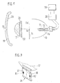
- FIG. 1 shows a headlamp in a greatly simplified illustration in a longitudinal section
- FIG. 2 shows the headlamp in a detailed illustration
- FIG. 3 shows a detail shown in FIG. 2 with a perspective illustration.
- a low beam headlight for motor vehicles shown in FIG. 1 it has a reflector 10, in the back of which a gas discharge lamp 11 is inserted. Ellipses result in the vertical and horizontal meridian section of the reflector 10, the axial arc 12 of the gas discharge lamp 11 being arranged in the region of the inner focal point Fe of the ellipses on the optical axis 13 of the reflector. In the direction of the light rays reflected by the reflector 10, an aperture 14 with an optically effective upper edge 15 is arranged below the optical axis 13 in the area of the outer focus Fe 'of the ellipses.
- a lens 17 and a light disk 18 covering the light outlet opening of the headlight are arranged in the light exit direction, which can be designed as a diffusing screen.
- the light beams represent the upper edge 15 of the diaphragm 14 via the lens 17 as the light-dark boundary of the light distribution of the headlight.
- the gas discharge lamp 11 is supplied with the high voltage required for its operation by an ignition device 20 which is fed by the electrical system of the motor vehicle and controlled by a control device 19. In addition to visible light, the gas discharge lamp 11 also emits light in the UV wavelength range with high intensity during its operation.
- the lens 17 serves as a UV filter and is provided with a coating 23 which absorbs UV light.
- the coating 23 can be formed by a thin metal layer, for example made of gold or chrome. However, the coating 23 can also be formed by a fluoride layer.
- the lens 17 can also be given UV-light-absorbing properties by a suitable glass material or by admixtures to the glass material.
- a disk-shaped UV filter 22 can be arranged between the gas discharge lamp 11 and the lens 18, or the lens 18 can serve as a UV filter by means of a coating 23 or a suitable glass material.
- the coating 23 of the lens 18 not only shields the UV radiation, this also represents a compensation for the glass optics shown in the lens 18, so that undesired scattering of the light rays passing through is reduced.
- the coating 23 heats up due to the absorbed UV radiation, which leads to a heating of the lens 18. Heating of the lens 18 to accelerate the drying and defrosting of the lens without the use of external energy is thus achieved.
- the lens 18 can also be used even by appropriate selection of the glass material or by appropriate additions to the glass material have the property of absorbing UV light. A brownish coloring of the coating 23 or the lens 18 can give the light emerging from the headlight a coloring, so that it looks 'warmer'.
- the coating 23 or the lens 18 can be designed so that blue light is partially absorbed so that the light emerging from the headlight appears less blue.
- the coloring of the coating 23 or the lens 18 likewise heats the lens 18 when the gas discharge lamp 11 is in operation.
- a disc-shaped filter 22 is shown between the gas discharge lamp 11 and the lens 18, which is shown with a broken line in FIG a glass material has the property of absorbing UV light.
- the gas discharge lamp 11 is inserted into the reflector 10 via a lamp holder 26 and covered on its rear side with a cap 27.
- a carrier 28 is connected to the front edge of the reflector 10 and extends in the direction of light exit and has a holder 29 for receiving the lens 17 at its end pointing away from the reflector 10.
- the carrier 28 is designed as a hollow cylinder closed on its circumference and consists of sheet metal.
- the reflector 10 forms a tight bond with the support 28 and the lens 17, so that neither through these parts nor between them of the headlight covering lens 18 is arranged, which can be designed as a lens.
- the light beams represent the upper edge 15 of the diaphragm 14 via the lens 17 as the light-dark boundary of the light distribution of the headlight.
- the lens 17 serves as a UV filter and is provided with a coating 23 which absorbs UV light.
- the coating 23 can be designed as described in the first exemplary embodiment.
- the lens 17 can also be given UV-light-absorbing properties by a suitable glass material or by admixtures to the glass material.
- a disk-shaped UV filter 22 can be arranged between the gas discharge lamp 11 and the lens 18, or the lens 18 can serve as a UV filter by means of a coating 23 or a suitable glass material.
- FIGS. 3 and 4 show a third exemplary embodiment of the headlight, in which, as in the second exemplary embodiment, the objective 17 serves as a UV filter and has the property of absorbing UV light by means of a coating or a suitable glass material or additions to the glass material.
- the gas discharge lamp 11 is inserted into the reflector 10 via a lamp holder 26 and covered on its rear side with a cap 27.
- a carrier 28 is connected to the front edge of the reflector 10 and extends in the direction of light exit and has a holder 29 for receiving the lens 17 at its end pointing away from the reflector 10.
- the carrier 28 is designed as a hollow cylinder closed on its circumference and consists of sheet metal.
- the reflector 10 forms a tight bond with the support 28 and the lens 17, so that neither through these parts nor between them UV radiation can escape.
- a frame 31 is arranged toward the lens 18 and has an opening 32 the size of the objective 17 for the passage of light.
- the lens 17 can be inserted into the carrier 28 from its end facing the reflector 10 and comes to rest against a radially inwardly facing edge 33 of the carrier 28 forming part of the holder 29, against which it is held by a spring ring 30 becomes.
- the spring ring 30 is open in its lower area.
- a stop 36 which here is a rivet, between which and the edge 33 the edge of the objective 17 and the spring ring 30 come to rest when the objective is assembled.
- a ceramic plate 34 preferably diametrically opposite, can be fastened to the carrier 28, which projects radially inward through the open area of the spring ring 30 when the lens 17 is mounted and overlaps the edge of the lens 17 to the side of the reflector 10. The ceramic plate 34 could also serve to fix the position of the objective 17 at this point if the spring ring 30 is dispensed with.
- An electrical conductor track 37 is vapor-deposited on the ceramic plate 34 and is connected via signal lines 38 to the electrical control device 19 which controls the ignition device 20.
- the ceramic plate 34 has a predetermined breaking point determined by a notch 39, the conductor track 37 on the ceramic plate 34 extending beyond the notch 39.
- the notch 39 is arranged in such a way that when a force of a certain size acts on the lens 17 in the direction of the reflector 10, the ceramic plate 34 is broken by the lens 17 moving as a result of the counter-holder 36 in its lower region from the holder 29, thereby the conductor track 37 is interrupted.
- the ceramic plate 34 can be arranged at a small distance from the lens so that it does not vibrate during operation Exposed to the lens, which could lead to an unwanted break. An interruption of the conductor track 37 is recognized by a safety circuit of the control device 19 and the operation of the gas discharge lamp 11 is prevented. This ensures that, for example in the event of a lens 17 damaged as a result of an accident, no UV radiation emerges from the headlight and no parts under high voltage can be touched. However, if only the lens 18 is destroyed and the lens 17 is still in its holder 29, the headlight can continue to be operated since the combination of the parts reflector, support and lens is still intact and no harmful UV radiation can escape.
- the frame 28, the ceramic plate 34 and their electrical connections are covered by the frame 31.
- a voltage divider circuit can be applied to the ceramic plate 34, which has two resistors R1 and R2, across which a defined voltage drop occurs. Due to the predetermined breaking, one of the lines of the voltage divider is interrupted, so that the voltage drop in relation to the other branch of the voltage divider circuit changes significantly and the fault is thus indicated. If a voltage drop that deviates from the predetermined voltage drop occurs, this is recognized by the safety circuit of the control device 19 and the operation of the gas discharge lamp 11 is prevented. It is thus excluded that, for example, by short-circuiting the signal lines 38, the gas discharge lamp 11 can be operated even when the lens 17 is damaged.
Landscapes
- Engineering & Computer Science (AREA)
- General Engineering & Computer Science (AREA)
- Physics & Mathematics (AREA)
- Spectroscopy & Molecular Physics (AREA)
- Non-Portable Lighting Devices Or Systems Thereof (AREA)
- Diffracting Gratings Or Hologram Optical Elements (AREA)
- Studio Devices (AREA)
- Measurement Of Optical Distance (AREA)
Abstract
Claims (14)
- Phare pour véhicule automobile avec un réflecteur (10), une lampe luminescente à gaz (11) et une vitre (18) recouvrant l'ouverture de sortie de la lumière du phare, tandis que sur le trajet des rayons lumineux réfléchis par le réflecteur (10) et de ceux directement émis par la lampe luminescente à gaz (11) vers la vitre (18), est disposé un filtre (17) en forme de disque qui absorbe tout au moins partiellement la lumière dans la gamme des longueurs d'onde de l'ultraviolet, phare caractérisé en ce que, sur le trajet des rayons lumineux réfléchis par le réflecteur (10), est disposé un diaphragme (14), en ce que, sur le trajet des rayons lumineux influencés par le diaphragme (14), est disposé un objectif (17) grâce auquel un bord (15) du diaphragme (14) figure la limite clair-obscur de la répartition de lumière, en ce que l'objectif (17) est muni d'un revêtement (23) absorbant la lumière dans la gamme des longueurs d'ondes de l'ultraviolet, ou bien est constitué d'un matériau absorbant la lumière dans l'ultraviolet et jouant le rôle du filtre, et en ce que l'objectif (17) est disposé dans un support (29), ce support (29) comportant un composant (34) avec une ligne électrique (37) et cette ligne électrique (37) est rompue lorsque l'objectif (17) heurte le composant (34) avec une force déterminée, tandis que lorsque la ligne (37) est rompue une exploitation de la lampe luminescente à gaz (11) est empêchée.
- Phare selon la revendication 1, caractérisé en ce qu'en outre un autre filtre (22) disposé entre la lampe luminescente à gaz (11) et la vitre (18) est prévu sous la forme d'un disque muni d'un revêtement (23) absorbant la lumière ultraviolette ou bien constitué d'un matériau absorbant la lumière ultraviolette.
- Phare selon la revendication 1, caractérisé en ce qu'en outre la vitre (18) est munie d'un revêtement (23) absorbant la lumière ultraviolette ou bien est constituée d'un matériau absorbant la lumière ultraviolette.
- Phare selon l'une des précédentes revendications, caractérisé en ce que le filtre (17 ; 18 ; 22) est muni d'un revêtement métallique (23) en or ou en chrome.
- Phare selon l'une des revendications 1 à 3, caractérisé en ce que le filtre (17 ; 18 ; 22) est muni d'un revêtement de fluorure.
- Phare selon l'une des précédentes revendications, caractérisé en ce que le filtre (17 ; 18 ; 22) a une coloration brunâtre.
- Phare selon l'une des précédentes revendications, caractérisé en ce que le filtre (17 ; 18 ; 22) absorbe la lumière dans la gamme des longueurs d'ondes bleues.
- Phare selon l'une des précédentes revendications, caractérisé en ce que la ligne est réalisée sous la forme d'une piste conductrice (37) rapportée sur le composant (34), et le composant (34), lorsque l'objectif (17) le heurte, est rompu par celui-ci de façon que la piste conductrice (37) soit interrompue.
- Phare selon la revendication 8, caractérisé en ce que le composant (34) est en céramique et est muni d'un emplacement (39) destiné à la rupture.
- Phare selon l'une des précédentes revendications, caractérisé en ce que la ligne (37) est reliée par l'intermédiaire de lignes d'ordres (38) à un appareil électrique de commande (19), l'empêchement du fonctionnement de la lampe luminescente à gaz (11) lors de la rupture de la ligne (37) ou de la ligne d'ordres (38) s'effectuant grâce à un montage de sécurité de l'appareil de commande (19).
- Phare selon la revendication 10, caractérisé en ce que sur la ligne (37) est prévu un montage diviseur de tension, et en ce que l'appareil de commande (19) comporte un montage d'exploitation grâce auquel, lors d'une chute de tension sur la ligne (37) différente de la chute de tension prédéfinie par le montage diviseur de tension, le fonctionnement de la lampe luminescente à gaz (11) est empêché.
- Phare selon la revendication 11, caractérisé en ce que le montage diviseur de tension est disposé sur le composant (34).
- Phare selon l'une des précédentes revendications, caractérisé en ce que l'objectif (17) est disposé dans un support (28) relié au réflecteur (10) et qui est réalisé sous la forme d'un cylindre creux fermé sur sa périphérie.
- Phare selon l'une des précédentes revendications, caractérisé en ce que l'objectif (17) est maintenu en application contre un bord (33) du support, dirigé radialement vers l'intérieur, par un anneau (30) élastique radialement susceptible d'être mis en place dans le support (28).
Applications Claiming Priority (5)
| Application Number | Priority Date | Filing Date | Title |
|---|---|---|---|
| DE4019641 | 1990-06-20 | ||
| DE4019641 | 1990-06-24 | ||
| DE4109657 | 1991-03-23 | ||
| DE4109657A DE4109657A1 (de) | 1990-06-20 | 1991-03-23 | Scheinwerfer fuer kraftfahrzeuge |
| PCT/DE1991/000493 WO1991019938A1 (fr) | 1990-06-20 | 1991-06-12 | Phare pour vehicule automobile |
Publications (2)
| Publication Number | Publication Date |
|---|---|
| EP0487679A1 EP0487679A1 (fr) | 1992-06-03 |
| EP0487679B1 true EP0487679B1 (fr) | 1995-05-24 |
Family
ID=25894307
Family Applications (1)
| Application Number | Title | Priority Date | Filing Date |
|---|---|---|---|
| EP91911253A Expired - Lifetime EP0487679B1 (fr) | 1990-06-20 | 1991-06-12 | Phare pour vehicule automobile |
Country Status (5)
| Country | Link |
|---|---|
| US (1) | US5289352A (fr) |
| EP (1) | EP0487679B1 (fr) |
| JP (1) | JPH05500879A (fr) |
| DE (2) | DE4109657A1 (fr) |
| WO (1) | WO1991019938A1 (fr) |
Families Citing this family (15)
| Publication number | Priority date | Publication date | Assignee | Title |
|---|---|---|---|---|
| JPH0789448B2 (ja) * | 1991-03-19 | 1995-09-27 | 株式会社小糸製作所 | 自動車用投射型ヘッドランプ |
| JP2768074B2 (ja) * | 1991-09-09 | 1998-06-25 | 日産自動車株式会社 | 灯 具 |
| US5400223A (en) * | 1993-07-14 | 1995-03-21 | General Electric Company | Sports lighting luminaire having a broken glass safety shutdown circuit |
| FR2707764B1 (fr) * | 1993-07-16 | 1995-09-08 | Holophane | Glace de phare à filtre UV sélectif. |
| DE4445187A1 (de) * | 1994-12-17 | 1996-06-20 | Hella Kg Hueck & Co | Scheinwerfer für Fahrzeuge |
| FR2759765B1 (fr) * | 1997-02-18 | 1999-06-04 | Valeo Vision | Projecteur du type elliptique, notamment pour vehicule automobile |
| DE19839194B4 (de) | 1998-08-28 | 2010-01-28 | Automotive Lighting Reutlingen Gmbh | Scheinwerfer für Fahrzeuge nach dem Projektionsprinzip |
| DE19907365A1 (de) * | 1999-02-20 | 2001-01-04 | Matthias Rettig | Augenfreundliches Xenon-Scheinwerferlicht durch den Einbau eines Schutzfilters einer Schutzfilterfolie |
| CZ297837B6 (cs) * | 2001-05-15 | 2007-04-11 | Autopal, S. R. O. | Drzák cocky projektoru |
| FR2850616B1 (fr) * | 2003-01-30 | 2006-02-17 | Valeo Vision | Procede d'eclairage module d'une route et projecteur de vehicule mettant en oeuvre ce procede |
| DE102004047324A1 (de) * | 2004-09-29 | 2006-04-13 | Osram Opto Semiconductors Gmbh | Leuchtdiodenanordnung |
| DE102007043113A1 (de) | 2007-09-10 | 2009-03-12 | Robert Bosch Gmbh | Scheinwerfer für Fahrzeuge |
| ES1072079Y (es) * | 2010-01-15 | 2010-08-12 | Soluciones Fotoluminiscentes Sl | Obturador fotoluminiscente accionador de la luz de cruce y carretera para faros bixenon |
| DE102015213460A1 (de) * | 2015-07-17 | 2017-01-19 | Osram Gmbh | Wellenlängenumwandlung von Primärlicht mittels eines Konversionskörpers |
| US9803835B2 (en) * | 2015-09-23 | 2017-10-31 | Angel Technologies Holdings, Inc. | System and method of snow and ice removal |
Family Cites Families (10)
| Publication number | Priority date | Publication date | Assignee | Title |
|---|---|---|---|---|
| CH536459A (de) * | 1970-12-10 | 1973-04-30 | Battelle Memorial Institute | Vorrichtung zum Beleuchten der Fahrstrecke eines Fahrzeuges sowie zum Schutz des Fahrzeugführers gegen Blendung |
| GB1364927A (en) * | 1972-11-10 | 1974-08-29 | Feldmesser K | Automobile headlamps |
| US4386292A (en) * | 1980-07-02 | 1983-05-31 | Gte Products Corporation | Projection lamp comprising single ended arc discharge lamp and an interference filter |
| JPH07105316B2 (ja) * | 1985-08-13 | 1995-11-13 | 旭硝子株式会社 | 電気二重層コンデンサ用分極性電極及びその製造方法 |
| JPS6318703U (fr) * | 1986-07-21 | 1988-02-06 | ||
| SE458594B (sv) * | 1987-10-22 | 1989-04-17 | Labino Patent Ab | Straalkastare foer fordon |
| JPH01244934A (ja) * | 1988-03-28 | 1989-09-29 | Nissan Motor Co Ltd | 車両用前照灯装置 |
| GB2222449B (en) * | 1988-09-06 | 1992-01-02 | Top Line Leisure Ltd | Improvements in or relating to search lamps and torches |
| US4951178A (en) * | 1988-10-05 | 1990-08-21 | Koito Manfacturing Co., Ltd. | Headlight for motor vehicle |
| DE3936374C2 (de) * | 1989-11-02 | 1999-06-10 | Bayerische Motoren Werke Ag | Kraftfahrzeugscheinwerfer mit abtaubarer Abdeckscheibe |
-
1991
- 1991-03-23 DE DE4109657A patent/DE4109657A1/de not_active Withdrawn
- 1991-06-12 JP JP3510518A patent/JPH05500879A/ja active Pending
- 1991-06-12 DE DE59105580T patent/DE59105580D1/de not_active Expired - Fee Related
- 1991-06-12 US US07/834,275 patent/US5289352A/en not_active Expired - Fee Related
- 1991-06-12 EP EP91911253A patent/EP0487679B1/fr not_active Expired - Lifetime
- 1991-06-12 WO PCT/DE1991/000493 patent/WO1991019938A1/fr not_active Ceased
Also Published As
| Publication number | Publication date |
|---|---|
| EP0487679A1 (fr) | 1992-06-03 |
| WO1991019938A1 (fr) | 1991-12-26 |
| DE59105580D1 (de) | 1995-06-29 |
| JPH05500879A (ja) | 1993-02-18 |
| US5289352A (en) | 1994-02-22 |
| DE4109657A1 (de) | 1992-01-02 |
Similar Documents
| Publication | Publication Date | Title |
|---|---|---|
| EP0487679B1 (fr) | Phare pour vehicule automobile | |
| DE19655357B4 (de) | Fahrzeug-Scheinwerfer | |
| EP1160506B1 (fr) | Projecteur du genre elliptique pour véhicules et dispositif d' éclairage avec au moins un tel projecteur | |
| DE19731754C2 (de) | Kombination Infrarot-Laser-Abstandssensoren mit Scheinwerfern | |
| DE19704426B4 (de) | Scheinwerfer für Fahrzeuge nach dem Projektionsprinzip | |
| EP0890785A2 (fr) | Projecteur de véhicule | |
| DE2828856C2 (de) | Scheinwerfer für Kraftfahrzeuge | |
| DE68917555T2 (de) | Kraftfahrzeugscheinwerfer. | |
| EP1191279A2 (fr) | Projecteur pour véhicules | |
| DE10101789A1 (de) | Beleuchtungseinrichtung, insbesondere Scheinwerfer oder Scheinwerferleuchteneinheit, für Kraftfahrzeuge | |
| DE19839194A1 (de) | Scheinwerfer für Fahrzeuge nach dem Projektionsprinzip | |
| DE4019587A1 (de) | Scheinwerfer fuer kraftfahrzeuge | |
| DE1259747B (de) | Anordnung zum Verhindern von Phantomlicht in einer Signallichtanlage fuer Automobileod. dgl. | |
| DE19530950B4 (de) | Scheinwerfer für Fahrzeuge | |
| DE10330215A1 (de) | Scheinwerfer für Fahrzeuge | |
| DE19946351B4 (de) | Scheinwerfer für Fahrzeuge | |
| DE19750494B4 (de) | Verfahren zur Herstellung von Fernlichtscheinwerfern für Fahrzeuge | |
| EP0474806B1 (fr) | Phare pour vehicule a moteur | |
| EP1126211B1 (fr) | Projecteur de type elliptique pour véhicule automobile | |
| DE3415617C2 (de) | Scheinwerfer für Kraftfahrzeuge mit einer stark geneigten Abdeckscheibe und einem teils parabolischen, teils elliptischen Reflektor | |
| DE3427461A1 (de) | Lichtabgabevorrichtung, insbesondere fuer kraftfahrzeuge | |
| DE7724857U1 (de) | Lampenreflektoreinheit | |
| DE4135596A1 (de) | Scheinwerfer fuer kraftfahrzeuge | |
| EP1450099A2 (fr) | Projecteur de type a projection pour vehicules | |
| DE102012015265A1 (de) | Abschlussscheibe für eine Fahrzeugleuchte |
Legal Events
| Date | Code | Title | Description |
|---|---|---|---|
| PUAI | Public reference made under article 153(3) epc to a published international application that has entered the european phase |
Free format text: ORIGINAL CODE: 0009012 |
|
| 17P | Request for examination filed |
Effective date: 19920117 |
|
| AK | Designated contracting states |
Kind code of ref document: A1 Designated state(s): DE FR IT |
|
| 17Q | First examination report despatched |
Effective date: 19940518 |
|
| GRAA | (expected) grant |
Free format text: ORIGINAL CODE: 0009210 |
|
| AK | Designated contracting states |
Kind code of ref document: B1 Designated state(s): DE FR IT |
|
| ET | Fr: translation filed | ||
| REF | Corresponds to: |
Ref document number: 59105580 Country of ref document: DE Date of ref document: 19950629 |
|
| ITF | It: translation for a ep patent filed | ||
| PGFP | Annual fee paid to national office [announced via postgrant information from national office to epo] |
Ref country code: DE Payment date: 19960213 Year of fee payment: 5 |
|
| PLBE | No opposition filed within time limit |
Free format text: ORIGINAL CODE: 0009261 |
|
| STAA | Information on the status of an ep patent application or granted ep patent |
Free format text: STATUS: NO OPPOSITION FILED WITHIN TIME LIMIT |
|
| 26N | No opposition filed | ||
| PGFP | Annual fee paid to national office [announced via postgrant information from national office to epo] |
Ref country code: FR Payment date: 19960614 Year of fee payment: 6 |
|
| PG25 | Lapsed in a contracting state [announced via postgrant information from national office to epo] |
Ref country code: DE Effective date: 19970301 |
|
| PG25 | Lapsed in a contracting state [announced via postgrant information from national office to epo] |
Ref country code: FR Free format text: LAPSE BECAUSE OF NON-PAYMENT OF DUE FEES Effective date: 19980227 |
|
| REG | Reference to a national code |
Ref country code: FR Ref legal event code: ST |
|
| REG | Reference to a national code |
Ref country code: FR Ref legal event code: ST |
|
| PG25 | Lapsed in a contracting state [announced via postgrant information from national office to epo] |
Ref country code: IT Free format text: LAPSE BECAUSE OF NON-PAYMENT OF DUE FEES;WARNING: LAPSES OF ITALIAN PATENTS WITH EFFECTIVE DATE BEFORE 2007 MAY HAVE OCCURRED AT ANY TIME BEFORE 2007. THE CORRECT EFFECTIVE DATE MAY BE DIFFERENT FROM THE ONE RECORDED. Effective date: 20050612 |