EP0487737A1 - Method of controlling operations of galvanometer for scanner - Google Patents
Method of controlling operations of galvanometer for scanner Download PDFInfo
- Publication number
- EP0487737A1 EP0487737A1 EP91909842A EP91909842A EP0487737A1 EP 0487737 A1 EP0487737 A1 EP 0487737A1 EP 91909842 A EP91909842 A EP 91909842A EP 91909842 A EP91909842 A EP 91909842A EP 0487737 A1 EP0487737 A1 EP 0487737A1
- Authority
- EP
- European Patent Office
- Prior art keywords
- galvanometer
- command current
- acceleration
- memory
- scanning
- Prior art date
- Legal status (The legal status is an assumption and is not a legal conclusion. Google has not performed a legal analysis and makes no representation as to the accuracy of the status listed.)
- Granted
Links
Images



Classifications
-
- B—PERFORMING OPERATIONS; TRANSPORTING
- B23—MACHINE TOOLS; METAL-WORKING NOT OTHERWISE PROVIDED FOR
- B23K—SOLDERING OR UNSOLDERING; WELDING; CLADDING OR PLATING BY SOLDERING OR WELDING; CUTTING BY APPLYING HEAT LOCALLY, e.g. FLAME CUTTING; WORKING BY LASER BEAM
- B23K9/00—Arc welding or cutting
- B23K9/12—Automatic feeding or moving of electrodes or work for spot or seam welding or cutting
- B23K9/127—Means for tracking lines during arc welding or cutting
- B23K9/1272—Geometry oriented, e.g. beam optical trading
- B23K9/1274—Using non-contact, optical means, e.g. laser means
Definitions
- the present invention relates to a system for controlling the operation of a galvanometer used in a welding robot as a scanner for an arc sensor which senses a weld line, and more particularly, to an operation control system for a scanning galvanometer having an increased effective operating angle range.
- galavanometers capable of detecting a swing angle are used as a scanner for an arc sensor, to achieve an accurate scanning of a laser beam.
- the present invention was created in view of the above circumstances, and an object thereof is to provide an operation control system for a scanning galvanometer in which the swing angle is accurately controlled over an entire operating angle whereby a measurement using a laser beam can be effectively carried out.
- the present invention provides an operation control system for a scanning galvanometer associated with an arc sensor of a welding robot for sensing a weld line and having a swing mirror integral therewith for a laser beam scanning, the operation control system comprising a memory for storing waveform data of a galvanometer drive command current obtained by adding up currents corresponding to a swing angle of the galvanometer, an angular velocity of the swing angle, and an angular acceleration of the swing angle, an address circuit for causing the waveform data to be output from the memory at predetermined intervals, a D/A converter for converting an output from the memory into an analog value, a galvanometer drive circuit for amplifying an output signal of the D/A converter and driving the galvanometer, and the swing mirror being rotated together with the galvanometer.
- the galvanometer drive command current is obtained by synthesizing a constant-speed command current and an acceleration/deceleration command current, and waveform data thereof is stored in the memory.
- the address circuit causes the waveform data to be output from the memory at predetermined intervals, the D/A converter converts the output of the memory to an analog value, and the galvanometer drive circuit drives the galvanometer.
- the swing mirror is rotated together with the galvanometer for sensing a weld line.
- the galvanometer is driven at a constant angular velocity in swing angle regions other than the turning points, and at a constant angular acceleration at the turning points, in accordance with the waveform of the galvanometer drive command current, whereby the swing angle is accurately controlled over the entire operating range. Further, the change of direction of the swing angle at each turning point is effected in a very short time, and thus overshoot does not occur at the turning points of the triangular wave. Accordingly, the measurement for sensing a weld line by a laser beam scanning can be effectively carried out.
- FIG. 2 illustrates the external appearance of a welding robot.
- a torch 3 is attached to a distal end of a hand 2 of the robot 1, and is provided with an arc sensor unit 20, and the robot 1 is controlled by a robot control system 7 provided with a built-in arc sensor control unit 10.
- FIG. 3 shows the torch 3 and peripheral elements thereof.
- an electrode 4 projects from the distal end of the torch 3
- workpieces 31 and 32 are stacked for welding
- the arc sensor unit emits a laser beam (search laser beam) 26 for detecting a join between the workpieces 31 and 32.
- search laser beam search laser beam
- FIG. 4 is a block diagram showing the arc sensor unit 20 and the arc sensor control unit 10.
- the arc sensor control unit 10 comprises a mirror scanning section 11, a laser drive section 12, and a signal detecting section 13.
- the mirror scanning section 11 includes a drive circuit for driving a scanning galvanometer 22 together with a swing mirror 23, mentioned later, and other elements as described in detail hereinafter.
- the arc sensor unit 20 is composed of a laser oscillator 21, the scanning galvanometer 22, the swing mirror 23, which is swung by the scanning galvanometer 22, a lens 24, and a light-receiving element 25.
- the scanning galvanometer 22 comprises a torsion spring, a magnet, a coil wound around the magnet, and a damper (none of which is shown), and the swing mirror 23 is securely attached to the shaft (not shown) of the galvanometer.
- the galvanometer 22 rotates the swing mirror 23 to an angle at which a torque proportional to a galvanometer drive command current flowing through the coil and a control torque exerted by the torsion spring are balanced, as described in detail later.
- the laser oscillator 21 is supplied with a drive power from the laser drive section 12 and effects a laser oscillation to thereby emit a laser beam 26.
- the galvanometer 22 is driven by a drive command current from the mirror scanning section 11, to thereby swing the swing mirror 23, and the motion of the swing mirror 23 causes the laser beam 26 to scan the workpieces 31 and 32 to thereby detect a join therebetween.
- the laser beam 26 is reflected by the workpieces 31 and 32, converged by the lens 24, and input to the light-receiving element 25.
- the light-receiving element 25 Upon receiving the incident light, the light-receiving element 25 outputs a signal, the join between the workpieces 31 and 32, and the location thereof, are detected on the basis of this signal, and the detection signals are supplied to the robot control system 7, which then positions the torch 3 at a welding start point based on those signals. After the start of the welding, the torch 3 is controlled such that it follows the weld line.
- FIG. 1 shows the mirror scanning section 11 in detail.
- a clock circuit 41 provides a clock signal to an address counter 42 which, upon receiving the clock signal, carries out a count and supplies an output to a memory 43.
- the memory 43 which is a ROM, stores waveform data of the galvanometer drive command current for driving the galvanometer 22.
- the waveform data of the galvanometer drive command current is output from the memory 43 and is converted to an analog signal by a D/A converter 44, and is then supplied to a scanner drive circuit 45.
- the scanner drive circuit 45 then drives the galvanometer 22, and accordingly the swing mirror 23, whereby a laser beam scanning is effected to detect the weld line.
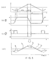
- FIG. 5 illustrates the procedure for determining the waveform of the galvanometer drive command current.
- the waveform of the drive command current I is obtained in the following manner:
- This equation (1) implies that, if the swing angle ⁇ , the angular velocity d ⁇ /dt and the angular acceleration d2 ⁇ /dt2 are set and substituted in the equation (1), and the obtained current value I is supplied to the galvanometer 22 as the drive command current, the galvanometer 22 will perform the assumed motion.
- the constants J, C, and K are values peculiar to the galvanometer 22, and are obtained by experiment.
- the waveform of the galvanometer drive command current I obtained in the above manner is a superposition of an acceleration/deceleration command current Ib on a triangular wave current Ia, as shown in FIG. 5(d).
- the waveform of the acceleration/deceleration command current Ib consists of a second order curve, and a command period ⁇ T1 thereof is 1/50 to 1/100 of the period ⁇ T of the drive command current I. Accordingly, the change of direction of the swing angle of the galvanometer 22 at the turning points is carried out in a very short time, and the motion of the galvanometer thereat is performed at the constant angular acceleration ⁇ .
- the drive command current I shown in FIG. 5(d) is obtained by compensating for the delay of the operation of the galvanometer with respect to the basic triangular wave current Io.
- the waveform of the drive command current I supplied to the galvanometer 22 is obtained by superposing the acceleration/deceleration command current Ib on the triangular wave current Ia, and thus the galvanometer 22 is driven at the constant angular velocity ⁇ in swing angle regions other than the turning points, and at the constant angular acceleration ⁇ in the vicinity of the turning points, in accordance with the waveform of the drive command current I. Accordingly, the swing angle is accurately controlled over the entire operating range, and the change of direction of the swing angle at the turning points is effected in a very short time. Further, overshoot does not occur at the turning points of the triangular wave, and as a result, the measurement for sensing the weld line by a laser beam scanning can be effectively carried out.
- the scanning galvanometer is driven in accordance with the waveform of the galvanometer drive command current in such a manner that it is driven at a constant angular velocity in swing angle regions other than the turning points, and at a constant angular acceleration in the vicinity of the turning points. Accordingly, the swing angle of the galvanometer is accurately controlled over the entire operating range, and the change of direction of the swing angle at the turning points is effected in a very short time. Further, overshoot does not occur at the turning points of the triangular wave, whereby the measurement for detecting the weld line by a laser beam scanning can be effectively carried out.
Landscapes
- Physics & Mathematics (AREA)
- Engineering & Computer Science (AREA)
- Optics & Photonics (AREA)
- Geometry (AREA)
- Plasma & Fusion (AREA)
- Mechanical Engineering (AREA)
- Laser Beam Processing (AREA)
- Mechanical Optical Scanning Systems (AREA)
- Length Measuring Devices By Optical Means (AREA)
- Manipulator (AREA)
Abstract
Description
- The present invention relates to a system for controlling the operation of a galvanometer used in a welding robot as a scanner for an arc sensor which senses a weld line, and more particularly, to an operation control system for a scanning galvanometer having an increased effective operating angle range.
- Conventionally, galavanometers capable of detecting a swing angle are used as a scanner for an arc sensor, to achieve an accurate scanning of a laser beam.
- This type of galvanometer, however, has a relatively large size due to the size of the swing-angle detection mechanism incorporated therein, requires a special drive circuit, has a complicated structure, and is expensive. Further, the detected swing angle is output as an analog value, and therefore, an A/D converter is required; this makes the control circuit complicated and susceptible to noise.
- Accordingly, inexpensive and small-sized galvanometers having no swing-angle detecting function are now used, as such galvanometers can be operated by simply supplying a drive current thereto, and thus have a simple construction of circuit and are not influenced by noise.
- Nevertheless, such conventional galvanometers having no swing-angle detecting funtion are operated by the following control methods, and still have problems.
- (1) The
galvanometer 22 shown in Fig. 6(a) is provided with anexternal mechanism 40 for detecting alaser beam 26 . Thisdetection mechanism 40 comprises a slit 40a and a light-receiving unit 40b, and thelaser beam 26 from alaser oscillator 21 is reflected by aswing mirror 23 and passed through the slit 40a. Then, using the swing angle ϑo of thegalvanometer 22 at this time as a reference, an arc sensor starts a measurement for detecting a weld line by using the laser beam.
Since thisgalvanometer 22 must be provided with thedetection mechanism 40 using a laser beam, however, it has a complicated structure. - (2) The
galvanometer 22 shown in FIG. 6(b) is operated by a drive command current having a sine waveform, and the swing angle ϑ of thegalvanometer 22 continuously follows the sine waveform, with a constant delay.
In thisgalvanometer 22, however, a change of the swing angle is small at regions A in the vicinity of the turning points where a leftward swing is changed to a rightward swing (or vice versa), but the arc sensor continuously measure the distance from the workpiece at predetermined intervals Δt (e.g., at intervals of 2560/sec). Accordingly, the frequency of measurement is relatively too high in the vicinity A of the turning points, and thus a part of the measurement is useless. - (3) When using a triangular wave to eliminate a useless part of the measurement present in the vicinity of the turning points, the
galvanometer 22 follows the triangular wave B with a constant delay, as shown in FIG. 6(c). - Nevertheless, overshoot occurs at the turning points, and further, the delay direction is reversed for the rightward and leftward swings with respect to the triangular wave B. Accordingly, the measurement cannot be carried out accurately at regions C in the vicinity of the turning points, and thus the measurement at these regions cannot be used.
- The present invention was created in view of the above circumstances, and an object thereof is to provide an operation control system for a scanning galvanometer in which the swing angle is accurately controlled over an entire operating angle whereby a measurement using a laser beam can be effectively carried out.
- To achieve the above object, the present invention provides an operation control system for a scanning galvanometer associated with an arc sensor of a welding robot for sensing a weld line and having a swing mirror integral therewith for a laser beam scanning, the operation control system comprising a memory for storing waveform data of a galvanometer drive command current obtained by adding up currents corresponding to a swing angle of the galvanometer, an angular velocity of the swing angle, and an angular acceleration of the swing angle, an address circuit for causing the waveform data to be output from the memory at predetermined intervals, a D/A converter for converting an output from the memory into an analog value, a galvanometer drive circuit for amplifying an output signal of the D/A converter and driving the galvanometer, and the swing mirror being rotated together with the galvanometer.
- The galvanometer drive command current is obtained by synthesizing a constant-speed command current and an acceleration/deceleration command current, and waveform data thereof is stored in the memory. The address circuit causes the waveform data to be output from the memory at predetermined intervals, the D/A converter converts the output of the memory to an analog value, and the galvanometer drive circuit drives the galvanometer. The swing mirror is rotated together with the galvanometer for sensing a weld line.
- Namely, the galvanometer is driven at a constant angular velocity in swing angle regions other than the turning points, and at a constant angular acceleration at the turning points, in accordance with the waveform of the galvanometer drive command current, whereby the swing angle is accurately controlled over the entire operating range. Further, the change of direction of the swing angle at each turning point is effected in a very short time, and thus overshoot does not occur at the turning points of the triangular wave. Accordingly, the measurement for sensing a weld line by a laser beam scanning can be effectively carried out.
-
- FIG. 1 is a diagram showing a mirror scanning section in detail;
- FIG. 2 is a view showing an external appearance of a welding robot;
- FIG. 3 is a view showing in detail a torch and peripheral elements thereof;
- FIG. 4 is a block diagram showing an arc sensor unit and an arc sensor control unit;
- FIG. 5 is a diagram illustrating the procedure for determining the waveform of a galvanometer drive command current; and
- FIGS. 6(a), 6(b), and 6(c) are diagrams each illustrating a control system for a conventional galvanometer having no detecting function.
-
- An embodiment of the present invention will be described with reference to the drawings.
- FIG. 2 illustrates the external appearance of a welding robot. As shown in the Figure, a
torch 3 is attached to a distal end of ahand 2 of the robot 1, and is provided with anarc sensor unit 20, and the robot 1 is controlled by arobot control system 7 provided with a built-in arcsensor control unit 10. - FIG. 3 shows the
torch 3 and peripheral elements thereof. As shown in the Figure, an electrode 4 projects from the distal end of thetorch 3,workpieces workpieces - FIG. 4 is a block diagram showing the
arc sensor unit 20 and the arcsensor control unit 10. The arcsensor control unit 10 comprises amirror scanning section 11, alaser drive section 12, and asignal detecting section 13. Themirror scanning section 11 includes a drive circuit for driving ascanning galvanometer 22 together with aswing mirror 23, mentioned later, and other elements as described in detail hereinafter. - The
arc sensor unit 20 is composed of alaser oscillator 21, thescanning galvanometer 22, theswing mirror 23, which is swung by thescanning galvanometer 22, alens 24, and a light-receivingelement 25. - The
scanning galvanometer 22 comprises a torsion spring, a magnet, a coil wound around the magnet, and a damper (none of which is shown), and theswing mirror 23 is securely attached to the shaft (not shown) of the galvanometer. Thegalvanometer 22 rotates theswing mirror 23 to an angle at which a torque proportional to a galvanometer drive command current flowing through the coil and a control torque exerted by the torsion spring are balanced, as described in detail later. - The
laser oscillator 21 is supplied with a drive power from thelaser drive section 12 and effects a laser oscillation to thereby emit alaser beam 26. Thegalvanometer 22 is driven by a drive command current from themirror scanning section 11, to thereby swing theswing mirror 23, and the motion of theswing mirror 23 causes thelaser beam 26 to scan theworkpieces laser beam 26 is reflected by theworkpieces lens 24, and input to the light-receivingelement 25. Upon receiving the incident light, the light-receivingelement 25 outputs a signal, the join between theworkpieces robot control system 7, which then positions thetorch 3 at a welding start point based on those signals. After the start of the welding, thetorch 3 is controlled such that it follows the weld line. - FIG. 1 shows the
mirror scanning section 11 in detail. As shown in the Figure, a clock circuit 41 provides a clock signal to anaddress counter 42 which, upon receiving the clock signal, carries out a count and supplies an output to amemory 43. Thememory 43, which is a ROM, stores waveform data of the galvanometer drive command current for driving thegalvanometer 22. The waveform data of the galvanometer drive command current is output from thememory 43 and is converted to an analog signal by a D/A converter 44, and is then supplied to ascanner drive circuit 45. Thescanner drive circuit 45 then drives thegalvanometer 22, and accordingly theswing mirror 23, whereby a laser beam scanning is effected to detect the weld line. - FIG. 5 illustrates the procedure for determining the waveform of the galvanometer drive command current. The waveform of the drive command current I is obtained in the following manner:
- (1) First, a performance waveform for the swing angle ϑ of the
galvanometer 22 is assumed (FIG. 5(a)), and basically the galvanometer is driven in accordance with a triangular wave, except for an acceleration/deceleration period ΔT1 in the vicinity of each turning point. The acceleration/deceleration period ΔT1 is set to the smallest possible value (e.g., 1/50 to 1/100 of the period ΔT, although this ΔT1 is exaggerated in the figure). The acceleration/deceleration period ΔT1 is restricted by the current-carrying capacity of thegalvanometer 22, and the current required increases as the acceleration/deceleration period ΔT1 is shortened. - (2) The angular velocity dϑ/dt of the swing angle ϑ is set (FIG. 5(b)) such that, during the acceleration/deceleration period ΔT1, the angular velocity dϑ/dt varies at a constant rate, and during the other period ΔT2, the angular velocity dϑ/dt is maintained at a predetermined value α.
- (3) The angular acceleration d²ϑ/dt² of the swing angle ϑ is set (FIG. 5(c)). To ensure that the angular velocity dϑ/dt will vary at a constant rate during the acceleration/deceleration period ΔT1, the angular acceleration d²ϑ/dt² is set to a predetermined value β. For the other period ΔT2, the angular velocity dϑ/dt is not varied, and thus the angular acceleration d²ϑ/dt² is set to zero.
- (4) The swing angle ϑ, the angular velocity dϑ/dt, and the angular acceleration d²ϑ/dt², set as above, are substituted in the following equation of motion (1) for the galvanometer, to obtain the drive command current I, and the
galvanometer 22 is driven by a drive torque proportional to the driving command current I.

where- J:
- sum of the moments of inertia of the
galvanometer 22 and theswing mirror 23; - C:
- viscosity coefficient of the
galvanometer 22; - K:
- torque coefficient of the
galvanometer 22; - ϑ:
- swing angle of the
galvanometer 22; - I:
- drive command current supplied to the
galvanometer 22.
- This equation (1) implies that, if the swing angle ϑ, the angular velocity dϑ/dt and the angular acceleration d²ϑ/dt² are set and substituted in the equation (1), and the obtained current value I is supplied to the
galvanometer 22 as the drive command current, thegalvanometer 22 will perform the assumed motion. The constants J, C, and K are values peculiar to thegalvanometer 22, and are obtained by experiment. - The waveform of the galvanometer drive command current I obtained in the above manner is a superposition of an acceleration/deceleration command current Ib on a triangular wave current Ia, as shown in FIG. 5(d).
- The waveform of the acceleration/deceleration command current Ib consists of a second order curve, and a command period ΔT1 thereof is 1/50 to 1/100 of the period ΔT of the drive command current I. Accordingly, the change of direction of the swing angle of the
galvanometer 22 at the turning points is carried out in a very short time, and the motion of the galvanometer thereat is performed at the constant angular acceleration β. - The drive command current I shown in FIG. 5(d) is obtained by compensating for the delay of the operation of the galvanometer with respect to the basic triangular wave current Io.
- Therefore, in the present embodiment, the waveform of the drive command current I supplied to the
galvanometer 22 is obtained by superposing the acceleration/deceleration command current Ib on the triangular wave current Ia, and thus thegalvanometer 22 is driven at the constant angular velocity α in swing angle regions other than the turning points, and at the constant angular acceleration β in the vicinity of the turning points, in accordance with the waveform of the drive command current I. Accordingly, the swing angle is accurately controlled over the entire operating range, and the change of direction of the swing angle at the turning points is effected in a very short time. Further, overshoot does not occur at the turning points of the triangular wave, and as a result, the measurement for sensing the weld line by a laser beam scanning can be effectively carried out. - As described above, according to the present invention, the scanning galvanometer is driven in accordance with the waveform of the galvanometer drive command current in such a manner that it is driven at a constant angular velocity in swing angle regions other than the turning points, and at a constant angular acceleration in the vicinity of the turning points. Accordingly, the swing angle of the galvanometer is accurately controlled over the entire operating range, and the change of direction of the swing angle at the turning points is effected in a very short time. Further, overshoot does not occur at the turning points of the triangular wave, whereby the measurement for detecting the weld line by a laser beam scanning can be effectively carried out.
Claims (6)
- An operation control system for a scanning galvanometer associated with an arc sensor of a welding robot for sensing a weld line, and having a swing mirror integral therewith for laser beam scanning, comprising:
a memory for storing waveform data of a galvanometer drive command current obtained by adding up currents corresponding to a swing angle of the galvanometer, an angular velocity of the swing angle, and an angular acceleration of the swing angle;
an address circuit for causing the waveform data to be output from the memory at predetermined intervals;
a D/A converter for converting an output from the memory to an analog value;
a galvanometer drive circuit for amplifying an output signal of the D/A converter and driving the galvanometer; and
the swing mirror being rotated together with the galvanometer. - An operation control system for a scanning galvanometer according to claim 1, wherein the galvanometer drive command current comprises
an acceleration/deceleration command current for setting a predetermined angular acceleration at which the galvanometer is driven at turning points of motion, and
a constant-speed command current for setting a predetermined angular velocity at which the galvanometer is driven in regions other than the motion turning points. - An operation control system for a scanning galvanometer according to claim 1, wherein a waveform of the acceleration/deceleration command current comprises a second order curve.
- An operation control system for a scanning galvanometer according to claim 1, wherein the acceleration/deceleration command current is employed for a very short command time.
- An operation control system for a scanning galvanometer according to claim 4, wherein the very short command time falls within a range of 1/50 to 1/100 of the period of the galvanometer drive command current.
- An operation control system for a scanning galvanometer according to claim 1, wherein the galvanometer drive command current is obtained by compensating for a delay in an operation of the galvanometer with respect to a drive command current.
Applications Claiming Priority (3)
| Application Number | Priority Date | Filing Date | Title |
|---|---|---|---|
| JP2164956A JP3001612B2 (en) | 1990-06-22 | 1990-06-22 | Operation control device of scanner galvanometer |
| JP164956/90 | 1990-06-22 | ||
| PCT/JP1991/000722 WO1992000542A1 (en) | 1990-06-22 | 1991-05-28 | Method of controlling operations of galvanometer for scanner |
Publications (3)
| Publication Number | Publication Date |
|---|---|
| EP0487737A1 true EP0487737A1 (en) | 1992-06-03 |
| EP0487737A4 EP0487737A4 (en) | 1992-10-21 |
| EP0487737B1 EP0487737B1 (en) | 1995-12-06 |
Family
ID=15803062
Family Applications (1)
| Application Number | Title | Priority Date | Filing Date |
|---|---|---|---|
| EP91909842A Expired - Lifetime EP0487737B1 (en) | 1990-06-22 | 1991-05-28 | Method of controlling operations of galvanometer for scanner |
Country Status (5)
| Country | Link |
|---|---|
| US (1) | US5214531A (en) |
| EP (1) | EP0487737B1 (en) |
| JP (1) | JP3001612B2 (en) |
| DE (1) | DE69115226T2 (en) |
| WO (1) | WO1992000542A1 (en) |
Cited By (2)
| Publication number | Priority date | Publication date | Assignee | Title |
|---|---|---|---|---|
| KR100392466B1 (en) * | 2000-02-29 | 2003-07-22 | 주식회사 이오테크닉스 | Apparatus and method for controlling galvanometer scanner device |
| CN115015876A (en) * | 2021-03-05 | 2022-09-06 | 上海禾赛科技有限公司 | Torsion structure of scanning galvanometer, scanning galvanometer and manufacturing method of torsion structure |
Families Citing this family (17)
| Publication number | Priority date | Publication date | Assignee | Title |
|---|---|---|---|---|
| US5546217A (en) * | 1993-11-05 | 1996-08-13 | Decagon Devices, Inc. | Laser scanning apparatus |
| US6741344B1 (en) | 1994-02-10 | 2004-05-25 | Affymetrix, Inc. | Method and apparatus for detection of fluorescently labeled materials |
| US6090555A (en) * | 1997-12-11 | 2000-07-18 | Affymetrix, Inc. | Scanned image alignment systems and methods |
| US5631734A (en) * | 1994-02-10 | 1997-05-20 | Affymetrix, Inc. | Method and apparatus for detection of fluorescently labeled materials |
| US20030017081A1 (en) * | 1994-02-10 | 2003-01-23 | Affymetrix, Inc. | Method and apparatus for imaging a sample on a device |
| US5650868A (en) * | 1995-06-07 | 1997-07-22 | Compaq Computer Corporation | Data transfer system |
| WO1997043611A1 (en) * | 1996-05-16 | 1997-11-20 | Affymetrix, Inc. | Systems and methods for detection of labeled materials |
| US7763827B2 (en) * | 2004-12-30 | 2010-07-27 | Medtronic, Inc. | Method and apparatus for laser welding incorporating galvanometer delivery |
| US8055098B2 (en) | 2006-01-27 | 2011-11-08 | Affymetrix, Inc. | System, method, and product for imaging probe arrays with small feature sizes |
| US9445025B2 (en) | 2006-01-27 | 2016-09-13 | Affymetrix, Inc. | System, method, and product for imaging probe arrays with small feature sizes |
| DE112008000450B4 (en) * | 2007-02-26 | 2020-10-15 | Hamamatsu Photonics K.K. | Light source device, observation device and processing device |
| US7806585B2 (en) * | 2007-06-22 | 2010-10-05 | Decagon Devices, Inc. | Apparatus, method, and system for measuring water activity and weight |
| KR20090039042A (en) * | 2007-10-17 | 2009-04-22 | 삼성전자주식회사 | An image forming apparatus having an optical scanning device and its position alignment method |
| JP5238479B2 (en) * | 2008-04-01 | 2013-07-17 | 株式会社トプコン | Method for driving MEMS mirror scanner, method for driving MEMS actuator scanner, and method for controlling rotation angle of MEMS actuator |
| JP5176823B2 (en) * | 2008-09-25 | 2013-04-03 | ブラザー工業株式会社 | Optical scanning device, image display device, and driving method of optical scanning device |
| CN110976439B (en) * | 2019-12-24 | 2020-10-20 | 中国科学院半导体研究所 | Laser cleaning mode and equipment for improving uniformity of laser cleaning surface |
| KR102590227B1 (en) * | 2023-06-15 | 2023-10-17 | 주식회사 인포웍스 | Galvano Mirror Scanner |
Family Cites Families (8)
| Publication number | Priority date | Publication date | Assignee | Title |
|---|---|---|---|---|
| US3321766A (en) * | 1966-06-08 | 1967-05-23 | Cons Electrodynamics Corp | Closed-loop galvanometer servo system |
| DE2827074A1 (en) * | 1977-06-21 | 1979-01-04 | Canon Kk | RECORDING DEVICE |
| JPS5574511A (en) * | 1978-11-30 | 1980-06-05 | Toshiba Corp | Driving system of optical scanning device |
| US4568816A (en) * | 1983-04-19 | 1986-02-04 | Unimation, Inc. | Method and apparatus for manipulator welding apparatus with improved weld path definition |
| JPS60117102A (en) * | 1983-11-30 | 1985-06-24 | Hitachi Ltd | Welding line tracing detection device |
| GB2157419A (en) * | 1984-04-11 | 1985-10-23 | Elco Ass R D | Optical sensor for for use in controlling a robot |
| JPS61157932U (en) * | 1985-03-20 | 1986-09-30 | ||
| JPH0637273A (en) * | 1992-07-17 | 1994-02-10 | Toshiba Corp | Semiconductor device and manufacture thereof |
-
1990
- 1990-06-22 JP JP2164956A patent/JP3001612B2/en not_active Expired - Lifetime
-
1991
- 1991-05-28 DE DE69115226T patent/DE69115226T2/en not_active Expired - Fee Related
- 1991-05-28 EP EP91909842A patent/EP0487737B1/en not_active Expired - Lifetime
- 1991-05-28 WO PCT/JP1991/000722 patent/WO1992000542A1/en not_active Ceased
- 1991-05-28 US US07/834,566 patent/US5214531A/en not_active Expired - Fee Related
Cited By (2)
| Publication number | Priority date | Publication date | Assignee | Title |
|---|---|---|---|---|
| KR100392466B1 (en) * | 2000-02-29 | 2003-07-22 | 주식회사 이오테크닉스 | Apparatus and method for controlling galvanometer scanner device |
| CN115015876A (en) * | 2021-03-05 | 2022-09-06 | 上海禾赛科技有限公司 | Torsion structure of scanning galvanometer, scanning galvanometer and manufacturing method of torsion structure |
Also Published As
| Publication number | Publication date |
|---|---|
| EP0487737B1 (en) | 1995-12-06 |
| DE69115226T2 (en) | 1996-05-02 |
| JPH0456820A (en) | 1992-02-24 |
| US5214531A (en) | 1993-05-25 |
| EP0487737A4 (en) | 1992-10-21 |
| WO1992000542A1 (en) | 1992-01-09 |
| JP3001612B2 (en) | 2000-01-24 |
| DE69115226D1 (en) | 1996-01-18 |
Similar Documents
| Publication | Publication Date | Title |
|---|---|---|
| EP0487737B1 (en) | Method of controlling operations of galvanometer for scanner | |
| US4524282A (en) | Electro-optical level detector | |
| US4800271A (en) | Galvanometric optical scanning system having synchronization photodetectors | |
| US5724123A (en) | Distance measuring equipment for detecting a scanning direction | |
| US4214154A (en) | Light beam scanning apparatus | |
| US3717772A (en) | Linear bidirectional scanning system | |
| CA1277411C (en) | Ultrasonic mine survey probe | |
| EP0869384A1 (en) | Mirror angle detector and detection method | |
| US3731098A (en) | Image scanner drive system | |
| Leigh-Lancaster et al. | Development of a laser tracking system | |
| JPH0529883A (en) | Compensation device for optoelectronic reference generator | |
| US4123167A (en) | Optical detecting system | |
| JP2726326B2 (en) | Arc sensor and welding line search method | |
| EP0364572A1 (en) | Apparatus for tracking the surface of a workpiece | |
| JPS63231286A (en) | Tracking distance measuring device for moving objects using laser beam | |
| USRE30938E (en) | Line edge follower | |
| JPS61226198A (en) | Laser beam machining control device | |
| JPH0421812A (en) | Beam scanner | |
| JPS6082277A (en) | Sensor for following up weld line | |
| JP2524140Y2 (en) | Laser light scanning device | |
| KR920004331B1 (en) | Laser lighting indicator | |
| JPS58198779A (en) | Ultrasonic sensor device | |
| JPS61502809A (en) | Improved product processing equipment | |
| JPS61234306A (en) | Optical measuring apparatus | |
| JPS60203362A (en) | automatic welding equipment |
Legal Events
| Date | Code | Title | Description |
|---|---|---|---|
| PUAI | Public reference made under article 153(3) epc to a published international application that has entered the european phase |
Free format text: ORIGINAL CODE: 0009012 |
|
| 17P | Request for examination filed |
Effective date: 19920311 |
|
| AK | Designated contracting states |
Kind code of ref document: A1 Designated state(s): DE IT SE |
|
| A4 | Supplementary search report drawn up and despatched |
Effective date: 19920828 |
|
| AK | Designated contracting states |
Kind code of ref document: A4 Designated state(s): DE IT SE |
|
| 17Q | First examination report despatched |
Effective date: 19940310 |
|
| GRAA | (expected) grant |
Free format text: ORIGINAL CODE: 0009210 |
|
| AK | Designated contracting states |
Kind code of ref document: B1 Designated state(s): DE IT SE |
|
| REF | Corresponds to: |
Ref document number: 69115226 Country of ref document: DE Date of ref document: 19960118 |
|
| ITF | It: translation for a ep patent filed | ||
| PLBE | No opposition filed within time limit |
Free format text: ORIGINAL CODE: 0009261 |
|
| STAA | Information on the status of an ep patent application or granted ep patent |
Free format text: STATUS: NO OPPOSITION FILED WITHIN TIME LIMIT |
|
| 26N | No opposition filed | ||
| PGFP | Annual fee paid to national office [announced via postgrant information from national office to epo] |
Ref country code: SE Payment date: 20000504 Year of fee payment: 10 |
|
| PGFP | Annual fee paid to national office [announced via postgrant information from national office to epo] |
Ref country code: DE Payment date: 20000529 Year of fee payment: 10 |
|
| PG25 | Lapsed in a contracting state [announced via postgrant information from national office to epo] |
Ref country code: SE Free format text: LAPSE BECAUSE OF NON-PAYMENT OF DUE FEES Effective date: 20010529 |
|
| PG25 | Lapsed in a contracting state [announced via postgrant information from national office to epo] |
Ref country code: DE Free format text: LAPSE BECAUSE OF NON-PAYMENT OF DUE FEES Effective date: 20020301 |
|
| PG25 | Lapsed in a contracting state [announced via postgrant information from national office to epo] |
Ref country code: IT Free format text: LAPSE BECAUSE OF NON-PAYMENT OF DUE FEES;WARNING: LAPSES OF ITALIAN PATENTS WITH EFFECTIVE DATE BEFORE 2007 MAY HAVE OCCURRED AT ANY TIME BEFORE 2007. THE CORRECT EFFECTIVE DATE MAY BE DIFFERENT FROM THE ONE RECORDED. Effective date: 20050528 |