EP0487786A2 - Relais - Google Patents
Relais Download PDFInfo
- Publication number
- EP0487786A2 EP0487786A2 EP90124909A EP90124909A EP0487786A2 EP 0487786 A2 EP0487786 A2 EP 0487786A2 EP 90124909 A EP90124909 A EP 90124909A EP 90124909 A EP90124909 A EP 90124909A EP 0487786 A2 EP0487786 A2 EP 0487786A2
- Authority
- EP
- European Patent Office
- Prior art keywords
- section
- armature
- shaped
- contact
- relay according
- Prior art date
- Legal status (The legal status is an assumption and is not a legal conclusion. Google has not performed a legal analysis and makes no representation as to the accuracy of the status listed.)
- Granted
Links
- 230000013011 mating Effects 0.000 claims abstract description 8
- 238000005192 partition Methods 0.000 claims description 4
- 239000012774 insulation material Substances 0.000 claims description 2
- 239000011810 insulating material Substances 0.000 abstract 1
- 238000009413 insulation Methods 0.000 description 4
- 238000010276 construction Methods 0.000 description 1
- 238000004804 winding Methods 0.000 description 1
Images

Classifications
-
- H—ELECTRICITY
- H01—ELECTRIC ELEMENTS
- H01H—ELECTRIC SWITCHES; RELAYS; SELECTORS; EMERGENCY PROTECTIVE DEVICES
- H01H50/00—Details of electromagnetic relays
- H01H50/02—Bases; Casings; Covers
- H01H50/026—Details concerning isolation between driving and switching circuit
-
- H—ELECTRICITY
- H01—ELECTRIC ELEMENTS
- H01H—ELECTRIC SWITCHES; RELAYS; SELECTORS; EMERGENCY PROTECTIVE DEVICES
- H01H50/00—Details of electromagnetic relays
- H01H50/64—Driving arrangements between movable part of magnetic circuit and contact
- H01H50/641—Driving arrangements between movable part of magnetic circuit and contact intermediate part performing a rectilinear movement
- H01H50/642—Driving arrangements between movable part of magnetic circuit and contact intermediate part performing a rectilinear movement intermediate part being generally a slide plate, e.g. a card
Definitions
- the invention relates to an electromagnetic relay with a base body, on which an electromagnetic system with a coil, core, yoke and armature is arranged and in which a contact arrangement with at least one mating contact element and at least one movable contact spring is anchored at a distance from the magnet system, the contact spring being one with the or the contact section interacting with the counter-contact elements, has a fastening section anchored in the base body and an actuating section which is connected to an actuating element made of insulation material and transmitting the armature movement to the contact spring.
- a relay in which the armature and the contact arrangement are attached to the same end of the coil, the armature being located between the coil and the contact arrangement, is known from DE 8701349 U.
- This relay does not use a slide, so that a smaller design is achieved, but here the contact spring and armature are conductively connected to each other, since the insulation requirements are met by overmolding the winding.
- the object of the invention is therefore to design a relay of the type mentioned in such a way that the prescribed clearance and creepage distance requirements are met with the smallest possible construction volume, without the coil having to be specially designed.
- the actuating element has a cap-shaped, funnel-shaped shielding section and a sliding section connected to the armature, the shielding section being slipped over the actuating section of the contact spring.
- the base body is expediently formed with a base plate forming the connection side and with a U-shaped intermediate wall provided for separating the areas for the magnet system and the contact arrangement, which can be integrally formed on the base body.
- the side wall of the shielding section of the actuating element facing the connection side has an opening, the shielding section being slipped over the actuating section of the contact spring from this side in a direction perpendicular to the base plate.
- the shielding section does not enclose the actuating section of the contact spring on four sides, but it can nevertheless be designed in such a way that the necessary air and creepage distances are maintained.
- a possible realization of the connection between the sliding section of the actuating element and the armature can be achieved in that the sliding section is hook-shaped and engages over a pin formed on the free end of the armature.
- the sliding section in a funnel-shaped manner and to place it over a pin formed on the anchor.
- the actuating element formed from a shielding section and a plate-shaped sliding section in two parts, connecting elements being provided on both parts and on the armature, which enable the shielding section to interact with the sliding section and the sliding section with the armature.
- a pin is preferably formed on the shielding section and recesses are provided on the sliding section, into which the pin of the shielding section and a pin formed on the free end of the armature engage.
- recesses it is also possible to provide recesses both on the shielding section and on the armature, into which pins formed on the sliding section engage.
- the design according to the invention can be used particularly advantageously in a relay in which the armature is attached to the end face of the coil between the coil and the contact arrangement.
- the plane of movement of the armature of the contact spring and of the actuating element can run both perpendicularly and parallel to the end side.
- the contact spring is formed with a U-shaped and an L-shaped part, with one leg of the U-shaped part the contact section and the short leg of the L-shaped part the Form fastening section and wherein the other leg of the U-shaped part is connected to the long leg of the L-shaped part and forms the actuating section.
- a cap is provided with an intermediate wall projecting between the magnet system and the contact arrangement. This partition further increases the insulation between the magnet system and the contact arrangement.
- projections are provided in the interior of the shielding section, between which the actuating section of the contact spring is mounted, as a result of which a secure connection between the armature and the contact spring is ensured.
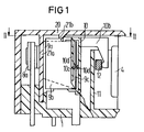
- the relay shown in FIGS. 1 and 2 has a base body 1 forming the connection side, on which a magnet system 2 and a contact arrangement 7 are arranged.
- the magnet system 2 is formed with a coil 3, a core 4, an angular yoke 5 and an armature 6 fastened to the yoke 5 by means of a spring 22, the armature 6 being arranged on the end face in front of the coil between the coil 3 and the contact arrangement 7.
- the contact arrangement 7 consists of two mating contact elements 8a and 8b and a movable contact spring 9, which are anchored in the base body 1 in slots or openings and guided to the connection side.
- the contact spring 9 in turn consists of a contact section 9a, which in the rest position shown is in contact with the mating contact element 8a, a fastening section 9b anchored in the base body 1 and an actuating section 9c.
- a sliding section 10b is formed on this actuation section 10a, which is hook-shaped and engages over a pin 12 formed on the free end of the armature 6, as a result of which the movement of the armature 6 is transmitted to the contact spring 9.
- a U-shaped intermediate wall 11 is formed on the base body 1, which serves to isolate the contact arrangement 7 from the magnet system 2 and over which the sliding section 10b of the actuating element 10 projects.
- the shielding section 10a of the actuating element 10 is open on its side facing the connection side and is placed over the actuation section 9c in a direction perpendicular to the connection side.
- the shielding section 10c it is also possible to design the shielding section 10c to be closed on all four sides, as a result of which it must be placed over the actuating section 9c in a direction running parallel to the connection side.
- a recess can be provided in the U-shaped partition 11 through which the hook-shaped sliding section 10b is guided.
- Knobs 10c and 10d are formed in the bottom region of the shielding section 10b which is designed as a cap and between which the actuating section 9c of the contact spring 9 is held.
- a cap 20 provided with intermediate walls 21a, 21b and 21c is placed on the base body 1 with the magnet system 2 and the contact arrangement 7 installed.
- the intermediate walls 21a and 21b have the task of shielding the mating contact elements 8a and 8b against the fastening section 9b and the actuating section 9c of the contact spring 9, while the intermediate wall 21c together with the actuating element 10 and the U-shaped intermediate wall 11 for isolating the actuating section 9c from the armature 6 serves. In this way, all clearances and creepage distances between the contact arrangement 7 and the magnet system 2 are large enough to meet the VDE requirements.
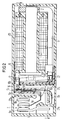
- the relay shown in Figures 3 and 4 realizes a further possible embodiment of the relay according to the invention, the plane in which the armature 6 and the contact spring 9 move is perpendicular to the connection side and thus opposite to that shown in Figures 1 and 2 Relay is rotated by 90 °. Parts having the same effect are provided here with the same reference numerals as in FIGS. 1 and 2.
- the armature 6 is provided at its free end with a pin 17 which projects into the funnel-shaped opening of the sliding section 23 of an actuating element 10.
- the actuating element 10 also has a cap-shaped, funnel-shaped shielding section 10a which is slipped over the actuating section 9c of a contact spring 9.
- the intermediate wall 24b is shown broken in Figure 4; it runs above the contact arrangement 7 with respect to the connection side, as can be seen in FIG.
- the U-shaped partition 11 has a lateral recess through which the actuating element 10 can be inserted.
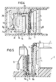
- FIG. 5 Another possible embodiment of the actuating element 11 is shown in FIG. 5.
- a funnel-shaped shielding section 13 is slipped over the contact spring 9, on which a pin 15 is formed.
- This pin 15 protrudes into a recess 16a of a plate-shaped sliding section 14, which has a further recess 16b, in which a pin 17, which is formed on the free end of an armature 6, is inserted.
- the contact spring 9 is, as in the two embodiments described above, composed of a U-shaped part 19 and an L-shaped part 18, one leg of the U-shaped part the contact portion, the short leg of the L-shaped part the Fastening section and the other leg of the U-shaped part, which is connected to the long leg of the L-shaped part, results in the actuating section.
Landscapes
- Physics & Mathematics (AREA)
- Electromagnetism (AREA)
- Electromagnets (AREA)
- Electronic Switches (AREA)
- Control Of Motors That Do Not Use Commutators (AREA)
- Seal Device For Vehicle (AREA)
- Relay Circuits (AREA)
- Slide Switches (AREA)
- Arc-Extinguishing Devices That Are Switches (AREA)
- Medicinal Preparation (AREA)
Applications Claiming Priority (2)
| Application Number | Priority Date | Filing Date | Title |
|---|---|---|---|
| DE9016264U DE9016264U1 (de) | 1990-11-29 | 1990-11-29 | Relais |
| DE9016264U | 1990-11-29 |
Publications (3)
| Publication Number | Publication Date |
|---|---|
| EP0487786A2 true EP0487786A2 (fr) | 1992-06-03 |
| EP0487786A3 EP0487786A3 (en) | 1993-02-24 |
| EP0487786B1 EP0487786B1 (fr) | 1994-11-30 |
Family
ID=6859834
Family Applications (1)
| Application Number | Title | Priority Date | Filing Date |
|---|---|---|---|
| EP90124909A Expired - Lifetime EP0487786B1 (fr) | 1990-11-29 | 1990-12-20 | Relais |
Country Status (4)
| Country | Link |
|---|---|
| EP (1) | EP0487786B1 (fr) |
| AT (1) | ATE114869T1 (fr) |
| DE (2) | DE9016264U1 (fr) |
| PT (1) | PT99633B (fr) |
Families Citing this family (6)
| Publication number | Priority date | Publication date | Assignee | Title |
|---|---|---|---|---|
| DE4115092C3 (de) * | 1991-05-08 | 1999-06-24 | Eberle Controls Gmbh | Elektromagnetisches Schaltrelais für Leiterplattenmontage |
| DE4226889C2 (de) * | 1991-09-17 | 1994-03-10 | Euro Matsushita Electric Works | Elektromagnetisches Relais |
| DE9111577U1 (de) * | 1991-09-17 | 1993-01-28 | EURO-Matsushita Electric Works AG, 8150 Holzkirchen | Elektromagnetisches Relais |
| DE9210790U1 (de) * | 1992-08-12 | 1993-12-16 | EURO-Matsushita Electric Works AG, 83607 Holzkirchen | Isolierteil für ein elektromagnetisches Relais |
| ATE170663T1 (de) * | 1995-03-21 | 1998-09-15 | Siemens Ag | Elektromagnetisches relais |
| DE19917338C2 (de) * | 1999-04-16 | 2002-05-08 | Tyco Electronics Logistics Ag | Elektromagnetisches Relais und Verfahren zu dessen Herstellung |
Family Cites Families (3)
| Publication number | Priority date | Publication date | Assignee | Title |
|---|---|---|---|---|
| DE2912800C2 (de) * | 1979-03-30 | 1985-04-25 | Siemens AG, 1000 Berlin und 8000 München | Elektromagnetisches Relais für hohe Schaltleistungen |
| DE8701349U1 (de) * | 1987-01-28 | 1988-05-26 | Siemens AG, 1000 Berlin und 8000 München | Elektromagnetisches Relais |
| DE3835118A1 (de) * | 1988-10-14 | 1990-04-19 | Siemens Ag | Elektromagnetisches relais |
-
1990
- 1990-11-29 DE DE9016264U patent/DE9016264U1/de not_active Expired - Lifetime
- 1990-12-20 AT AT90124909T patent/ATE114869T1/de not_active IP Right Cessation
- 1990-12-20 EP EP90124909A patent/EP0487786B1/fr not_active Expired - Lifetime
- 1990-12-20 DE DE59007875T patent/DE59007875D1/de not_active Expired - Lifetime
-
1991
- 1991-11-28 PT PT99633A patent/PT99633B/pt not_active IP Right Cessation
Also Published As
| Publication number | Publication date |
|---|---|
| PT99633B (pt) | 1999-02-26 |
| DE9016264U1 (de) | 1991-02-21 |
| DE59007875D1 (de) | 1995-01-12 |
| EP0487786A3 (en) | 1993-02-24 |
| PT99633A (pt) | 1993-11-30 |
| EP0487786B1 (fr) | 1994-11-30 |
| ATE114869T1 (de) | 1994-12-15 |
Similar Documents
| Publication | Publication Date | Title |
|---|---|---|
| DE4135305C2 (fr) | ||
| DE2454967B2 (de) | Gepoltes elektromagnetisches relais | |
| DE9211726U1 (de) | Elektromagnetisches Relais | |
| DE9001448U1 (de) | Schaltvorrichtung mit geschützten Unterbrechern | |
| DE2936101C2 (de) | Elektromagnetisches Relais | |
| EP0727797A1 (fr) | Interrupteur de sécurité | |
| EP0007637A1 (fr) | Dispositif de verrouillage des portes d'appareils ménagers | |
| DE4030333C2 (de) | Elektromagnetisches Schaltschütz | |
| EP0487786B1 (fr) | Relais | |
| EP0501951B1 (fr) | Relais electromagnetique | |
| WO2018054714A1 (fr) | Relais electromagnetique | |
| DE3938226C1 (en) | Miniature switching relay of H=section - providing double insulated chamber for magnet and contact systems | |
| DE3025814C2 (de) | Elektromagnetisches Relais | |
| DE3118292C2 (de) | Elektromagnetisches Relais | |
| EP0077017B1 (fr) | Relais électromagnétique polarisé | |
| DE3604548C3 (de) | Elektrische Verbinderanordnung mit einem Steuerflächensystem | |
| EP0249025A2 (fr) | Relais électromagnétique miniature | |
| DE19917338C2 (de) | Elektromagnetisches Relais und Verfahren zu dessen Herstellung | |
| EP1473752A1 (fr) | Déclencheur électromagnétique | |
| EP0502842B1 (fr) | Relais electromagnetique | |
| EP0393628B1 (fr) | Boîtier pour un composant électromécanique | |
| EP0133582A2 (fr) | Relais électromagnétique | |
| DE2402236C3 (de) | Steckbares, mit einem quaderförmigen Gehäuse versehenes, elektromagnetisches Relais | |
| DE2258479C3 (de) | Isoliereinrichtung für die Spule eines elektromagnetischen Flachrelais | |
| DE102016201409A1 (de) | Kamm für ein schmales Relais, Kammanordnung und Relais |
Legal Events
| Date | Code | Title | Description |
|---|---|---|---|
| PUAI | Public reference made under article 153(3) epc to a published international application that has entered the european phase |
Free format text: ORIGINAL CODE: 0009012 |
|
| 17P | Request for examination filed |
Effective date: 19901220 |
|
| AK | Designated contracting states |
Kind code of ref document: A2 Designated state(s): AT CH DE ES FR GB IT LI |
|
| PUAL | Search report despatched |
Free format text: ORIGINAL CODE: 0009013 |
|
| AK | Designated contracting states |
Kind code of ref document: A3 Designated state(s): AT CH DE ES FR GB IT LI |
|
| 17Q | First examination report despatched |
Effective date: 19940317 |
|
| GRAA | (expected) grant |
Free format text: ORIGINAL CODE: 0009210 |
|
| AK | Designated contracting states |
Kind code of ref document: B1 Designated state(s): AT CH DE ES FR GB IT LI |
|
| PG25 | Lapsed in a contracting state [announced via postgrant information from national office to epo] |
Ref country code: ES Free format text: THE PATENT HAS BEEN ANNULLED BY A DECISION OF A NATIONAL AUTHORITY Effective date: 19941130 |
|
| REF | Corresponds to: |
Ref document number: 114869 Country of ref document: AT Date of ref document: 19941215 Kind code of ref document: T |
|
| REF | Corresponds to: |
Ref document number: 59007875 Country of ref document: DE Date of ref document: 19950112 |
|
| ITF | It: translation for a ep patent filed | ||
| GBT | Gb: translation of ep patent filed (gb section 77(6)(a)/1977) |
Effective date: 19950207 |
|
| ET | Fr: translation filed | ||
| PLBE | No opposition filed within time limit |
Free format text: ORIGINAL CODE: 0009261 |
|
| STAA | Information on the status of an ep patent application or granted ep patent |
Free format text: STATUS: NO OPPOSITION FILED WITHIN TIME LIMIT |
|
| 26N | No opposition filed | ||
| PGFP | Annual fee paid to national office [announced via postgrant information from national office to epo] |
Ref country code: GB Payment date: 19981210 Year of fee payment: 9 |
|
| PGFP | Annual fee paid to national office [announced via postgrant information from national office to epo] |
Ref country code: AT Payment date: 19981211 Year of fee payment: 9 |
|
| PGFP | Annual fee paid to national office [announced via postgrant information from national office to epo] |
Ref country code: FR Payment date: 19981218 Year of fee payment: 9 |
|
| PGFP | Annual fee paid to national office [announced via postgrant information from national office to epo] |
Ref country code: CH Payment date: 19990311 Year of fee payment: 9 |
|
| PG25 | Lapsed in a contracting state [announced via postgrant information from national office to epo] |
Ref country code: AT Free format text: LAPSE BECAUSE OF NON-PAYMENT OF DUE FEES Effective date: 19991220 Ref country code: GB Free format text: LAPSE BECAUSE OF NON-PAYMENT OF DUE FEES Effective date: 19991220 |
|
| PG25 | Lapsed in a contracting state [announced via postgrant information from national office to epo] |
Ref country code: LI Free format text: LAPSE BECAUSE OF NON-PAYMENT OF DUE FEES Effective date: 19991231 Ref country code: CH Free format text: LAPSE BECAUSE OF NON-PAYMENT OF DUE FEES Effective date: 19991231 |
|
| REG | Reference to a national code |
Ref country code: CH Ref legal event code: PUE Owner name: SIEMENS AKTIENGESELLSCHAFT TRANSFER- TYCO ELECTRON Ref country code: CH Ref legal event code: NV Representative=s name: RIEDERER HASLER & PARTNER PATENTANWAELTE AG |
|
| GBPC | Gb: european patent ceased through non-payment of renewal fee |
Effective date: 19991220 |
|
| PG25 | Lapsed in a contracting state [announced via postgrant information from national office to epo] |
Ref country code: FR Free format text: LAPSE BECAUSE OF NON-PAYMENT OF DUE FEES Effective date: 20000831 |
|
| REG | Reference to a national code |
Ref country code: FR Ref legal event code: ST |
|
| PGFP | Annual fee paid to national office [announced via postgrant information from national office to epo] |
Ref country code: IT Payment date: 20091230 Year of fee payment: 20 |
|
| PGFP | Annual fee paid to national office [announced via postgrant information from national office to epo] |
Ref country code: DE Payment date: 20091230 Year of fee payment: 20 |
|
| PG25 | Lapsed in a contracting state [announced via postgrant information from national office to epo] |
Ref country code: DE Free format text: LAPSE BECAUSE OF EXPIRATION OF PROTECTION Effective date: 20101220 |