EP0487798B1 - Gerät zur Messung des Wasserinhaltes - Google Patents
Gerät zur Messung des Wasserinhaltes Download PDFInfo
- Publication number
- EP0487798B1 EP0487798B1 EP90312992A EP90312992A EP0487798B1 EP 0487798 B1 EP0487798 B1 EP 0487798B1 EP 90312992 A EP90312992 A EP 90312992A EP 90312992 A EP90312992 A EP 90312992A EP 0487798 B1 EP0487798 B1 EP 0487798B1
- Authority
- EP
- European Patent Office
- Prior art keywords
- microwave energy
- fluid
- microwave
- test cell
- temperature
- Prior art date
- Legal status (The legal status is an assumption and is not a legal conclusion. Google has not performed a legal analysis and makes no representation as to the accuracy of the status listed.)
- Expired - Lifetime
Links
- XLYOFNOQVPJJNP-UHFFFAOYSA-N water Substances O XLYOFNOQVPJJNP-UHFFFAOYSA-N 0.000 title claims description 14
- 238000012360 testing method Methods 0.000 claims description 56
- 239000012530 fluid Substances 0.000 claims description 44
- 210000004027 cell Anatomy 0.000 claims description 38
- 239000003208 petroleum Substances 0.000 claims description 12
- 239000000463 material Substances 0.000 claims description 5
- 210000005056 cell body Anatomy 0.000 claims description 3
- 230000001678 irradiating effect Effects 0.000 claims 2
- 239000000523 sample Substances 0.000 description 27
- 239000013074 reference sample Substances 0.000 description 13
- 238000010438 heat treatment Methods 0.000 description 5
- 230000010363 phase shift Effects 0.000 description 3
- 238000010586 diagram Methods 0.000 description 2
- 238000004519 manufacturing process Methods 0.000 description 2
- 238000005259 measurement Methods 0.000 description 2
- ZCYVEMRRCGMTRW-UHFFFAOYSA-N 7553-56-2 Chemical compound [I] ZCYVEMRRCGMTRW-UHFFFAOYSA-N 0.000 description 1
- 239000004809 Teflon Substances 0.000 description 1
- 229920006362 Teflon® Polymers 0.000 description 1
- 238000010521 absorption reaction Methods 0.000 description 1
- 239000002253 acid Substances 0.000 description 1
- 238000011109 contamination Methods 0.000 description 1
- 230000007423 decrease Effects 0.000 description 1
- 238000001514 detection method Methods 0.000 description 1
- 230000006870 function Effects 0.000 description 1
- 238000005469 granulation Methods 0.000 description 1
- 230000003179 granulation Effects 0.000 description 1
- 238000003780 insertion Methods 0.000 description 1
- 230000037431 insertion Effects 0.000 description 1
- 229910052740 iodine Inorganic materials 0.000 description 1
- 239000011630 iodine Substances 0.000 description 1
- 239000002184 metal Substances 0.000 description 1
- 238000000034 method Methods 0.000 description 1
- 239000000203 mixture Substances 0.000 description 1
- 238000012544 monitoring process Methods 0.000 description 1
- 230000003287 optical effect Effects 0.000 description 1
- 230000000704 physical effect Effects 0.000 description 1
- 239000007787 solid Substances 0.000 description 1
- 239000011343 solid material Substances 0.000 description 1
- 238000001228 spectrum Methods 0.000 description 1
- 230000003068 static effect Effects 0.000 description 1
Images
Classifications
-
- G—PHYSICS
- G01—MEASURING; TESTING
- G01N—INVESTIGATING OR ANALYSING MATERIALS BY DETERMINING THEIR CHEMICAL OR PHYSICAL PROPERTIES
- G01N22/00—Investigating or analysing materials by the use of microwaves or radio waves, i.e. electromagnetic waves with a wavelength of one millimetre or more
- G01N22/04—Investigating moisture content
-
- G—PHYSICS
- G01—MEASURING; TESTING
- G01N—INVESTIGATING OR ANALYSING MATERIALS BY DETERMINING THEIR CHEMICAL OR PHYSICAL PROPERTIES
- G01N33/00—Investigating or analysing materials by specific methods not covered by groups G01N1/00 - G01N31/00
- G01N33/26—Oils; Viscous liquids; Paints; Inks
- G01N33/28—Oils, i.e. hydrocarbon liquids
- G01N33/2823—Raw oil, drilling fluid or polyphasic mixtures
Definitions
- the present invention relates to water cut monitors in general and, more particularly, to microwave water cut monitors.
- a device as claimed in claim 1 but without the means to control the temperature of the sample is disclosed in EP-A-384 593.
- DE-A-39 02 755 discloses the use of a flow cell for optical absorption measurements of samples, which are solid or highly viscous at room temperature and particularly for the determination of oleochemical numbers like acid number or iodine number.
- the cell body comprises a fluid passage for the sample fluid, a chamber for the reference fluid and fluid passage for a hot fluid of 85°C, which is fed through the cell in order to avoid contamination of the walls of the sample fluid passage by heating these.
- An article of J. Kalinski in MIKROWELLENMAGAZIN discloses various features useful in the determination of water content, for example in a mixture of dielectric fluids and water. Disclosed are an appropriate flow cell, the technique of detection of attenuation and phase shift and generally means for preparing a sample such that it has the appropriate physical properties, such as density, homogeneity, granulation, thickness or temperature etc..
- a petroleum stream microwave water cut monitor includes test cell means which contains a reference petroleum multiphase fluid sample and which has a sample stream of a petroleum stream passing through it.
- the test cell is maintained at a predetermined temperature.
- a source provides microwave energy to one of a first pair antennae which provides the petroleum stream flowing in the test cell or the reference sample in the test cell with microwave energy.
- One of a second pair of antennae receives the microwave energy that has passed through either the petroleum stream or the reference sample.
- a detector detects the received microwave energy and provides a signal corresponding thereto.
- An indicator provides an indication of the water cut of the petroleum stream in accordance with the received signal power and a phase difference between the source provided microwave energy and the received microwave energy.
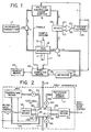
- Figure 1 is a partial simplified block diagram and a partial schematic of a microwave water cut monitor constructed in accordance with the present invention.
- FIG 2 is a simplified block diagram of the test apparatus shown in Figure 1.
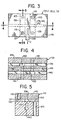
- Figure 3 is a drawing of the test cell shown in Figure 2.
- Figures 4 and 5 are cross-sectional drawings of the test cell shown in Figure 3.
- the water cut monitor shown in Figure 1 includes a microwave transmitter 3 providing electromagnetic energy, hereinafter referred to as microwave energy, at a microwave frequency.
- Transmitter 3 is low powered and may use a microwave gun source.
- Transmitter 3 provides microwave energy to directional coupler 4.
- Directional coupler 4 provides microwave energy to a conventional type voltage controlled phase shifter 5 and to test apparatus 8. All conductance or carrying of microwave energy is accomplished by using conventional type waveguides and coaxial cables.
- Test apparatus 8 has a line 10, carrying a sample stream of a multi-phase petroleum stream, entering apparatus 8.
- the sample stream leaves test apparatus 8 by way of a line 11.
- Apparatus 8 will be described in more detail hereinafter. Suffice to say at this point that microwave energy leaving test apparatus 8 hereinafter referred to as test microwave energy, is microwave energy that is either passed through the sample stream or has passed through a reference sample.
- the test microwave energy is applied to a directional coupler 18.
- Directional coupler 18 provides the test microwave energy to a detector 22 and to a mixer 28.
- Detector 22 provides a signal E1 corresponding to the power of the microwave energy received by the receiving antenna in apparatus 8.
- Voltage control phase shifter 5 provides microwave energy, hereinafter called the reference microwave energy, to mixer 28 which mixes the reference microwave energy and the test microwave energy to provide two electrical signals E2, E3, representative of the phases of the reference microwave energy and the test microwave energy, respectively.
- a differential amplifier 30 provides an output signal E0 in accordance with the difference between signals E2 and E3.
- Signal E0 is a function of the phase difference between the reference microwave energy and the test microwave energy and is provided to a feedback network 34.
- Feedback network 34 provides a signal C to voltage control phase shifter 5, controlling the phase of the reference microwave energy, and to a mini-computer means 40.
- Signal E0, and hence signal C decreases in amplitude until there is substantially 90° phase difference between the reference microwave energy and the test microwave energy.
- Voltage control phase shifter 5 indicates the amount of phase shift required to eliminate the phase difference.
- Signals E1, T and C are provided to a conventional type mini-computer means 40 which contains within it memory means having data related to phase and power for various percentages of water cuts that could be encountered in the production stream.
- Phase Shifter 5 also provides an enable signal to computer means 40 allowing computer means 40 to utilize signals T, C and E1 as address signals to select the proper water cut value.
- Computer means 40 provides signals, corresponding to the selected water cut value, to readout means 44 which may be either display means or record means or a combination of the two.
- test apparatus 8 includes a test cell 53.
- Test cell 53 will be described more fully hereinafter.
- Microwave energy from directional coupler 4 enters switch means 58 which provides microwave to test cell 53 through either a line 62 or a line 64.
- Line 62 provides the microwave to an antenna 63 which radiates the microwave energy into the sample stream.
- antenna 65 provides an antenna 65.
- Antenna 65 radiates the microwave energy into the reference sample.
- Line 66 carries test microwave energy received by an antenna 67 after it has passed through the sample stream.
- line 69 carries microwave energy received by an antenna 70 after it has passed through the reference sample.
- Switch means 72 receives the test microwave energy from either line 66 or line 67 and provides it to directional coupler 18.
- a reference sample source 77 provides the reference sample fluid to test cell 53 by way of a line 80 having a valve 84.
- a channel in test cell 53 connects line 80 to another line 88 having a valve 90.
- source 77 provides the reference fluid through test cell 53.
- a measurement could be made while it is flowing, or sample fluid could be contained in a static condition in test cell 53 by closing valve 90 until the channel within test cell 53 is completely filled.
- valve 84 is closed while valve 90 is opened.
- the present invention controls the temperature of the sample stream flowing through test cell 53.
- a pump 95 pumps a fluid heated to a predetermined temperature through a line 97 to test cell 53 which leaves test cell 53 by way of line 100.
- the heating fluid is provided to a temperature control means 105 which heats it to the predetermined temperature and provides it to pump 95.
- a temperature sensor 108 mounted in test cell 53 senses the temperature of test cell 53 and provides it back to temperature control means 105 so as to control the temperature of the heating fluid provided to pump 95.
- test cell 53 having microwave entrance ports 115 and 118.
- microwave exit ports 125 and 128 Connecting microwave entrance port 115 and microwave exit port 125 is a microwave channel 130.
- a microwave channel 132 connects microwave entrance port 118 with microwave exit port 128.
- fluid channels 136 and 140 are shown in Figure 3. Since fluid channels 136, 140 and 142 are in line in this view of test cell 53 only one set of dash lines represents them. This can seen better in Figure 4 which has a cut away view of test cell 53 along the line 4-4 in the direction of the arrows.
- a body 145 which may be made of metal having fluid channels 136, 140 and 142 passing through it longitudinally and microwave channels 130 and 132 for the microwave energy cut transversely through it. It should be noted that channels 130 and 132 are shown as being offset from each other. However this offset is not necessary to the practice of the present invention.
- fluid channels 136, 140 have a rectangular cross-section so that the microwave energy that passes through the fluids, always has the same distance of passage.
- FIG. 5 there is a view of test cell 53 along the line 5-5 in the direction of shown in Figure 3.
- Channel 130 is filled with a solid material 150, such as high density teflon, that is conductive to microwave energy, except for that portion of channel 130 that forms a cross-section of fluid channel 136.
- Cut into body 145 is microwave entrance port 115.
- another chamber 154 which connects microwave entrance port 111 and enters into material 150 in channel 130. This is for the insertion of microwave antenna 63, which may be of the commercial type made by Omni Spectra, Part No. 2057-5134-02, slightly modified for the present application.
- microwave exit port 125 for antenna 67, is shown with an additional chamber 155 which enters into material 150.
- exit port 125 is longer than entrance port 115.
- the microwave energy when applied to the antenna 63 enters material 150 and is directed to cross channel 136 until it reaches the antenna 67 inserted in exit port 125.
- lines 10 and 11 are connected in a conventional manner to channel 136 so that the sample stream in line 10 will flow through test cell 53 to line 11.
- lines 80 and 88 are connected to fluid channel 140 in such a manner that the sample fluid in line 80 will enter fluid channel 140 and exit test cell 53 through line 88.
- antenna 67 in entrance port 118 is connected to line 63 and antenna 70 in exit port 128 is connected to line 67.
- temperature sensor 108 which is a thermocouple, is inserted into a chamber cut into block 125 and thus reads the temperature of block 125 as the temperature of the reference sample and as of the production sample stream.
- lines 97 and 100 are connected in a conventional manner to fluid channel 142 so that the heating fluid flows through channel 142 and heats block 145.
- a preferred temperature is the temperature of the sample fluid entering test cell 53 from line 10 in which case it may be desirable to also test the temperature of the sample fluid in line 10 and provide a second temperature signal to the temperature control means. This has not shown in the drawings because the sample stream temperature may also be determined beforehand and is substantially constant. In either case the heating of block 125 will not add to the heat of the sample stream unless its temperature has changed. More important, however, the temperature of the sample stream as it passes through test cell 53 will be uniform.
- the reference sample will also be brought up to the temperature of the sample stream so that the data gathered from testing of both the sample stream and the reference sample will have a greater degree of accuracy.
- channel 142 is shown as being located between fluid channels 136 and 140 if pressure is a problem and the strength of block 125 is suspect, fluid channel 142 may be moved with the idea in mind that it should generally be equidistant from the sample stream flowing in fluid channel 136 and the reference sample in fluid channel 140 so as to keep them at the same temperature.
- the reference sample's power and phase shift is used as base line data in mini-computer means 40.
- the base line data and the test data derived from the petroleum sample stream are temperature corrected by mini-computer means 40.
- Mini-computer means 40 determines the water-cut in accordance with the corrected base line data, the corrected test data and look-up table stored in its memory.
Landscapes
- Chemical & Material Sciences (AREA)
- Physics & Mathematics (AREA)
- Health & Medical Sciences (AREA)
- Life Sciences & Earth Sciences (AREA)
- General Physics & Mathematics (AREA)
- Engineering & Computer Science (AREA)
- Biochemistry (AREA)
- General Health & Medical Sciences (AREA)
- Analytical Chemistry (AREA)
- Immunology (AREA)
- Pathology (AREA)
- Electromagnetism (AREA)
- Chemical Kinetics & Catalysis (AREA)
- General Chemical & Material Sciences (AREA)
- Oil, Petroleum & Natural Gas (AREA)
- Food Science & Technology (AREA)
- Medicinal Chemistry (AREA)
- Investigating Or Analyzing Materials Using Thermal Means (AREA)
- Investigating Or Analysing Materials By Optical Means (AREA)
Claims (6)
- Mikrowellen-Petroleumstromwassergehaltsmeßgerät mit:
einer Prüfzelle (53) zur Anordnung in einem Musterpetroleumstromfluß und zur Aufnahme einer Bezugspetroleummehrphasenflüssigkeit;
ersten Antennenmitteln (63,65) zum Bestrahlen des Flusses oder der Bezugsflüssigkeit mit Mikrowellenenergie;
zweiten Antennenmitteln (67,70) zum Empfangen von durch den Fluß oder die Bezugsflüssigkeit durchgeleiteter Mikrowellenenergie;
einem mit den besagten zweiten Antennenmitteln verbundenen Detektor (22) zum Erkennen der Intensität der Empfangsenergie und zur Bereitstellung eines diese darstellenden Signals;
Mitteln (5,34) zur Bereitstellung eines den Phasenunterschied zwischen der Mikrowellenbestrahlungsenergie und der Mikrowellenempfangsenergie darstellenden Signals;
Mitteln (40) zur Bereitstellung eines den Prozentsatz an Wassergehalt im Petroleumstrom darstellenden Signals entsprechend dem besagten Intensitätssignal und besagten Phasenunterschiedssignal;
wobei besagte Prüfzelle (53) einen Körper mit ersten, zweiten und dritten Flüssigkeitsdurchlaufkanälen (136,140,142) und ersten und zweiten Mikrowellenenergiedurchlaufkanälen (130,132) umfaßt;
wobei die besagten ersten und zweiten Flüssigkeitskanäle (136,140) besagte Fluß- bzw. besagte Bezugsflüssigkeit aufnehmen und besagte erste bzw. zweite Mikrowellenenergiekanäle schneiden können; und
mit der Prüfzelle (53) verbundenen Temperaturregelmitteln (105) zur Bereitstellung einer Temperaturregelflüssigkeit für den besagten dritten Flüssigkeitsdurchlaufkanal (142) durch den Prüfzellenkörper zur Aufrechterhaltung einer vorbestimmten Temperatur der Prüfzelle. - Meßgerät nach Anspruch 1, gekennzeichnet durch einen Temperaturfühler (108), der zum Abfühlen der Temperatur des besagten Prüfzellenkörpers (53) und zur Bereitstellung eines die abgefühlte Temperatur darstellenden Signals angeordnet ist.
- Meßgerät nach Anspruch 2, dadurch gekennzeichnet, daß das Temperaturregelmittel (105) einen Wärmetauscher (105) und Mittel (95) zum Umwälzen der besagten Temperaturregelflüssigkeit zwischen der Prüfzelle und dem Wärmetauscher enthält, wobei der besagte Wärmetauscher zur Aufrechterhaltung der besagten vorbestimmten Temperatur der Temperaturregelflüssigkeit auf besagtes Temperatursignal reagiert.
- Meßgerät nach Anspruch 2 oder Anspruch 3, dadurch gekennzeichnet, daß besagte Mittel (40) zur Bereitstellung eines Signals auch auf das besagte Temperatursignal reagieren.
- Meßgerät nach einem beliebigen der Ansprüche 1 bis 4, dadurch gekennzeichnet, daß die besagten ersten und zweiten Mikrowellenenergiekanäle (130,132) außer an den Schnittstellen mit dem ersten und zweiten Flüssigkeitskanal (136,140) mit Material angefüllt sind, wobei das besagte Material für Flüssigkeiten undurchlässig ist, aber den Durchlauf von Mikrowellenenergie erlaubt.
- Meßgerät nach einem beliebigen der Ansprüche 1 bis 5, dadurch gekennzeichnet, daß
die besagten ersten Antennenmittel (63,65) eine erste Antenne (63) zur Bereitstellung von Mikrowellenenergie in den besagten ersten Mikrowellenkanal (130), eine zweite Antenne (65) zur Bereitstellung von Mikrowellenenergie in den besagten zweiten Mikrowellenkanal (132) und einen ersten Schalter (58) zur gezielten Bereitstellung von Mikrowellenenergie von einer Quelle (3) zu den ersten und zweiten Antennen (63,65) umfassen;
die besagten zweiten Antennenmittel (67,70) eine erste Empfangsantenne (67) zum Empfangen von Mikrowellenenergie aus dem besagten ersten Mikrowellenkanal (130), eine zweite Empfangsantenne (70) zum Empfangen von Mikrowellenenergie aus dem besagten zweiten Mikrowellenkanal (132) und einen zweiten Schalter (72) zum gezielten Weitergeben von Mikrowellenenergie aus den besagten ersten und zweiten Empfangsantennen (67,70) zum besagten Detektor (22) umfassen.
Priority Applications (1)
| Application Number | Priority Date | Filing Date | Title |
|---|---|---|---|
| DE69022239T DE69022239D1 (de) | 1990-11-29 | 1990-11-29 | Gerät zur Messung des Wasserinhaltes. |
Applications Claiming Priority (1)
| Application Number | Priority Date | Filing Date | Title |
|---|---|---|---|
| US07/337,709 US4977377A (en) | 1989-04-13 | 1989-04-13 | Microwave water cut monitor with temperature controlled test cell |
Publications (2)
| Publication Number | Publication Date |
|---|---|
| EP0487798A1 EP0487798A1 (de) | 1992-06-03 |
| EP0487798B1 true EP0487798B1 (de) | 1995-09-06 |
Family
ID=23321680
Family Applications (1)
| Application Number | Title | Priority Date | Filing Date |
|---|---|---|---|
| EP90312992A Expired - Lifetime EP0487798B1 (de) | 1989-04-13 | 1990-11-29 | Gerät zur Messung des Wasserinhaltes |
Country Status (4)
| Country | Link |
|---|---|
| US (1) | US4977377A (de) |
| EP (1) | EP0487798B1 (de) |
| AU (1) | AU629717B2 (de) |
| CA (1) | CA2030444A1 (de) |
Families Citing this family (11)
| Publication number | Priority date | Publication date | Assignee | Title |
|---|---|---|---|---|
| DK0521059T3 (da) * | 1990-03-23 | 2000-07-31 | Commw Scient Ind Res Org | Bestemmelse af carbon i flyveaske |
| US5107219A (en) * | 1991-01-03 | 1992-04-21 | Texaco Inc. | Means and method for determining the conductance of a fluid |
| US5157339A (en) * | 1991-04-16 | 1992-10-20 | Atlantic Richfield Company | Method for measuring water-oil mixtures with relatively high gas content |
| US5644244A (en) * | 1991-06-21 | 1997-07-01 | Texaco Inc. | Method for analyzing a petroleum stream |
| US5546007A (en) * | 1993-01-07 | 1996-08-13 | Texaco Inc. | Microwave water cut monitoring means and method |
| JP3139874B2 (ja) * | 1993-03-30 | 2001-03-05 | 株式会社東芝 | 濃度計 |
| US5485743A (en) * | 1994-09-23 | 1996-01-23 | Schlumberger Technology Corporation | Microwave device and method for measuring multiphase flows |
| US6227041B1 (en) | 1998-09-17 | 2001-05-08 | Cem Corporation | Method and apparatus for measuring volatile content |
| US6411105B1 (en) * | 2000-09-11 | 2002-06-25 | The United States Of America As Represented By The Secretary Of The Navy | Nondestructive detection of steel surface corrosion |
| US6940295B2 (en) * | 2003-06-11 | 2005-09-06 | The Boeing Company | Apparatus and methods for non-destructive inspection using microwave sensing |
| US20230384133A1 (en) * | 2022-05-31 | 2023-11-30 | NeoTek Energy, Inc. | Multiphase Measurement System With Electromagnetic Water Cut Meter And Waxy Solids Control Systems |
Family Cites Families (14)
| Publication number | Priority date | Publication date | Assignee | Title |
|---|---|---|---|---|
| GB1545680A (en) * | 1976-06-25 | 1979-05-10 | Instrumentation Specialties Co | Measuring instrument |
| US4240028A (en) * | 1979-04-27 | 1980-12-16 | Texaco Inc. | Means and method for determining water saturation of oil |
| US4490676A (en) * | 1981-12-31 | 1984-12-25 | Texaco Inc. | Microwave means for monitoring fluid in a core of material |
| US4485284A (en) * | 1982-01-11 | 1984-11-27 | Advanced Moisture Technology, Inc. | Apparatus and process for microwave moisture analysis |
| US4499418A (en) * | 1982-08-05 | 1985-02-12 | Texaco Inc. | Water cut monitoring means and method |
| DE3412704A1 (de) * | 1983-04-06 | 1984-10-11 | Nippondenso Co., Ltd., Kariya, Aichi | Vorrichtung zum messen des alkoholgehaltes in kraftstoffgemischen |
| US4672322A (en) * | 1984-08-24 | 1987-06-09 | Milton Roy Company | High sensitivity conductivity detector |
| GB2179156B (en) * | 1985-08-14 | 1990-08-22 | Ronald Northedge | Flow meters |
| US4764718A (en) * | 1986-04-23 | 1988-08-16 | Chevron Research Company | Microwave oil saturation scanner |
| US4812739A (en) * | 1986-09-15 | 1989-03-14 | Swanson Claude V | Apparatus and method for using microwave radiation to measure water content of a fluid |
| US4774680B1 (en) * | 1986-09-19 | 1993-10-12 | Agar Corporation Ltd. | Method and apparatus for net oil measurement |
| US4767982A (en) * | 1987-06-01 | 1988-08-30 | Master Chemical Corporation | Concentration detection system |
| DE3902755A1 (de) * | 1989-01-31 | 1990-08-02 | Henkel Kgaa | Durchflusszelle |
| US4947127A (en) * | 1989-02-23 | 1990-08-07 | Texaco Inc. | Microwave water cut monitor |
-
1989
- 1989-04-13 US US07/337,709 patent/US4977377A/en not_active Expired - Lifetime
-
1990
- 1990-11-21 CA CA002030444A patent/CA2030444A1/en not_active Abandoned
- 1990-11-29 EP EP90312992A patent/EP0487798B1/de not_active Expired - Lifetime
- 1990-12-10 AU AU67911/90A patent/AU629717B2/en not_active Ceased
Also Published As
| Publication number | Publication date |
|---|---|
| AU629717B2 (en) | 1992-10-08 |
| CA2030444A1 (en) | 1992-05-22 |
| AU6791190A (en) | 1992-06-18 |
| EP0487798A1 (de) | 1992-06-03 |
| US4977377A (en) | 1990-12-11 |
Similar Documents
| Publication | Publication Date | Title |
|---|---|---|
| EP0384593B1 (de) | Mikrowellen-Überwachungsgerät von Wassergehalt | |
| EP0496144B1 (de) | Verfahren und Vorrichtung mit variierbarer Arbeitsweise zur Überwachung des Wassergehaltes unter Verwendung von Mikrowellen | |
| EP0487798B1 (de) | Gerät zur Messung des Wasserinhaltes | |
| US5014010A (en) | Dual frequency microwave water cut monitoring means and method | |
| CA2118404C (en) | Meter and method for in situ measurement of the electromagnetic properties of various materials using cutoff frequency characterization and analysis | |
| CA1311369C (en) | Microwave apparatus for measuring fluid mixtures | |
| US5107219A (en) | Means and method for determining the conductance of a fluid | |
| Nelson | A system for measuring dielectric properties at frequencies from 8.2 to 12.4 GHz | |
| US5644244A (en) | Method for analyzing a petroleum stream | |
| CA2105878C (en) | Method for measuring water-oil mixtures with relatively high gas content | |
| US4977915A (en) | Demulsifier control system and method | |
| Makeev et al. | Microwave measurement of water content in flowing crude oil | |
| US20050007123A1 (en) | Method and a device for monitoring the dispersed aqueous phase of an oil-water emulsion | |
| US4947128A (en) | Co-variance microwave water cut monitoring means and method | |
| US5546007A (en) | Microwave water cut monitoring means and method | |
| US5101164A (en) | Petroleum stream monitoring system and method with sample verification | |
| US5701083A (en) | Apparatus for measuring consistency and flow rate of a slurry | |
| JP3156184B2 (ja) | 二重周波数マイクロ波による含水率測定手段及び方法 | |
| US5234012A (en) | Petroleum stream control system and method | |
| KR0181736B1 (ko) | 석유흐름내 체적당 함수율 측정장치 및 방법 | |
| JP3180157B2 (ja) | 可変モードマイクロ波含水率監視装置 | |
| RU2789020C1 (ru) | Способ косвенного измерения теплопроводности по данным диэлькометрических измерений | |
| CA2030594A1 (en) | Variable mode microwave water cut monitor and method | |
| AU651078B2 (en) | Variable mode microwave water cut monitor and method | |
| Rzepecka et al. | Modified infinite sample method for routine permittivity measurements at microwave frequencies |
Legal Events
| Date | Code | Title | Description |
|---|---|---|---|
| PUAI | Public reference made under article 153(3) epc to a published international application that has entered the european phase |
Free format text: ORIGINAL CODE: 0009012 |
|
| AK | Designated contracting states |
Kind code of ref document: A1 Designated state(s): DE DK ES FR GB NL |
|
| 17P | Request for examination filed |
Effective date: 19921026 |
|
| 17Q | First examination report despatched |
Effective date: 19940922 |
|
| GRAA | (expected) grant |
Free format text: ORIGINAL CODE: 0009210 |
|
| AK | Designated contracting states |
Kind code of ref document: B1 Designated state(s): DE DK ES FR GB NL |
|
| PG25 | Lapsed in a contracting state [announced via postgrant information from national office to epo] |
Ref country code: NL Free format text: LAPSE BECAUSE OF NON-PAYMENT OF DUE FEES Effective date: 19950906 Ref country code: FR Effective date: 19950906 Ref country code: ES Free format text: THE PATENT HAS BEEN ANNULLED BY A DECISION OF A NATIONAL AUTHORITY Effective date: 19950906 Ref country code: DK Effective date: 19950906 |
|
| REF | Corresponds to: |
Ref document number: 69022239 Country of ref document: DE Date of ref document: 19951012 |
|
| PG25 | Lapsed in a contracting state [announced via postgrant information from national office to epo] |
Ref country code: DE Effective date: 19951207 |
|
| NLV1 | Nl: lapsed or annulled due to failure to fulfill the requirements of art. 29p and 29m of the patents act | ||
| EN | Fr: translation not filed | ||
| PLBE | No opposition filed within time limit |
Free format text: ORIGINAL CODE: 0009261 |
|
| STAA | Information on the status of an ep patent application or granted ep patent |
Free format text: STATUS: NO OPPOSITION FILED WITHIN TIME LIMIT |
|
| 26N | No opposition filed | ||
| PGFP | Annual fee paid to national office [announced via postgrant information from national office to epo] |
Ref country code: GB Payment date: 19980930 Year of fee payment: 9 |
|
| PG25 | Lapsed in a contracting state [announced via postgrant information from national office to epo] |
Ref country code: GB Free format text: LAPSE BECAUSE OF NON-PAYMENT OF DUE FEES Effective date: 19991129 |
|
| GBPC | Gb: european patent ceased through non-payment of renewal fee |
Effective date: 19991129 |