EP0487845A1 - Anneau de filtre - Google Patents
Anneau de filtre Download PDFInfo
- Publication number
- EP0487845A1 EP0487845A1 EP91115084A EP91115084A EP0487845A1 EP 0487845 A1 EP0487845 A1 EP 0487845A1 EP 91115084 A EP91115084 A EP 91115084A EP 91115084 A EP91115084 A EP 91115084A EP 0487845 A1 EP0487845 A1 EP 0487845A1
- Authority
- EP
- European Patent Office
- Prior art keywords
- ring
- wall
- filter
- grooves
- filter ring
- Prior art date
- Legal status (The legal status is an assumption and is not a legal conclusion. Google has not performed a legal analysis and makes no representation as to the accuracy of the status listed.)
- Granted
Links
Images

Classifications
-
- B—PERFORMING OPERATIONS; TRANSPORTING
- B01—PHYSICAL OR CHEMICAL PROCESSES OR APPARATUS IN GENERAL
- B01D—SEPARATION
- B01D25/00—Filters formed by clamping together several filtering elements or parts of such elements
- B01D25/02—Filters formed by clamping together several filtering elements or parts of such elements in which the elements are pre-formed independent filtering units, e.g. modular systems
-
- B—PERFORMING OPERATIONS; TRANSPORTING
- B01—PHYSICAL OR CHEMICAL PROCESSES OR APPARATUS IN GENERAL
- B01D—SEPARATION
- B01D29/00—Filters with filtering elements stationary during filtration, e.g. pressure or suction filters, not covered by groups B01D24/00 - B01D27/00; Filtering elements therefor
- B01D29/11—Filters with filtering elements stationary during filtration, e.g. pressure or suction filters, not covered by groups B01D24/00 - B01D27/00; Filtering elements therefor with bag, cage, hose, tube, sleeve or like filtering elements
- B01D29/13—Supported filter elements
- B01D29/15—Supported filter elements arranged for inward flow filtration
-
- B—PERFORMING OPERATIONS; TRANSPORTING
- B01—PHYSICAL OR CHEMICAL PROCESSES OR APPARATUS IN GENERAL
- B01D—SEPARATION
- B01D29/00—Filters with filtering elements stationary during filtration, e.g. pressure or suction filters, not covered by groups B01D24/00 - B01D27/00; Filtering elements therefor
- B01D29/96—Filters with filtering elements stationary during filtration, e.g. pressure or suction filters, not covered by groups B01D24/00 - B01D27/00; Filtering elements therefor in which the filtering elements are moved between filtering operations; Particular measures for removing or replacing the filtering elements; Transport systems for filters
-
- B—PERFORMING OPERATIONS; TRANSPORTING
- B01—PHYSICAL OR CHEMICAL PROCESSES OR APPARATUS IN GENERAL
- B01D—SEPARATION
- B01D2201/00—Details relating to filtering apparatus
- B01D2201/04—Supports for the filtering elements
- B01D2201/0415—Details of supporting structures
-
- B—PERFORMING OPERATIONS; TRANSPORTING
- B01—PHYSICAL OR CHEMICAL PROCESSES OR APPARATUS IN GENERAL
- B01D—SEPARATION
- B01D2201/00—Details relating to filtering apparatus
- B01D2201/40—Special measures for connecting different parts of the filter
- B01D2201/4084—Snap or Seeger ring connecting means
Definitions
- the invention relates to a filter ring for its insertion into annular openings or openings in the wall of gases or liquids receiving or through which hollow bodies flow, which filter ring in its wall enclosing a cavity has a slot extending parallel to the ring axis over the entire axial length of the ring, wherein the wall parts of the ring located on both sides of this slot are connected to one another by a snap lock.
- a filter ring has been put on the market by the applicant for several months.
- Filter rings of this type are generally used in grooves arranged on the outer sides of the hollow body wall, for example the wall of a tube, which are provided in the region of the opening or opening in the hollow body wall.
- the filter rings To insert them into these grooves, the filter rings must be widened or opened so that they can be pushed over the outer wall of the hollow body.
- the slot provided in the aforementioned known filter ring, which extends over the entire axial length of the ring and which allows separation of the ring wall at a circumferential point of the filter ring and thus expansion of the filter ring to a ring diameter, which slides over the outer surface of the hollow body allowed.
- the ring After inserting the filter ring into the groove, the ring can pass through Press together its wall parts located on both sides of the slot and their fixed connection can be closed again by means of the snap lock and brought to its initial diameter, which corresponds to the diameter of the groove base.
- the snap lock is formed by a locking rib which is arranged on one wall part of the ring, extends over the entire axial ring length and can be latched into a groove which is likewise arranged and extends on the other wall part. Since the snap should be held firmly, the opposite side surfaces of the locking rib and locking groove are undercut so that they engage behind each other (clip lock).
- this training requires a relatively large wall thickness of the ring, since the undercut locking rib and undercut groove are not practical in a thin-walled ring for reasons of space and strength.
- the invention is therefore based on the object in a filter ring of the type mentioned to make the connection of the wall parts located on both sides of its slot to one another in such a way that it is practical even with relatively thin-walled rings.
- the snap closure used to connect the two wall parts has at least two lugs, which are arranged side by side on the one wall part of the ring in its axial direction and can be snapped into grooves arranged next to one another on the other wall part of the ring, that the lugs and Grooves extend over the entire thickness of the ring wall and have undercut and undercut side surfaces in the connecting direction.
- These mutually engaging side surfaces can be seen in a side view of the Ring wall have essentially dovetail shape.
- the snap lock can also be accommodated on the wall of a relatively thin-walled filter ring without the strength of the filter ring and the snap connection being impaired.
- the end faces of these wall parts can abut in a connected position and interlock in this position, e.g. in arrow shape, be profiled.
- the lugs and grooves of the snap connection can be profiled in an interlocking manner on their opposite side walls. Both profiles can have an arrow shape.
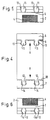
- the cylindrical wall of the filter ring 1 shown in the drawing has a frame which is formed by two ring-shaped webs 2 located at the ends of the filter ring and connecting connecting webs 3 which extend in the axial direction of the filter ring.
- a filter fabric 4 is clamped, through which a gas or a liquid can flow under filtration between the frame webs 2, 3.
- the filter fabric 4 can be welded into the frame parts 2, 3, 6, 7 and 8.
- One of the connecting webs 3 is separated by a longitudinal slot 5 into two wall parts 6 and 7, which longitudinal slot extends over the entire axial ring length.
- the diametrically opposite connecting web is formed by weakening the material to form a joint 8, by means of which the wall parts 6, 7 of the ring located on both sides of the separating slot 5 can be moved away from one another while widening.
- the two parts 6, 7 abut one another with their arrow-shaped profiled end faces 9, 10.
- two dovetail-shaped snap noses 11 are provided on one part 6, which are spaced apart in the axial direction of the ring arranged side by side and also arranged on the other wall part 7 and can also be snapped into dovetail grooves 12 arranged on the other wall part 7.
- the lugs and grooves extend over the entire thickness of the ring wall, as can be seen from FIGS. 3, 5 and 6.
- the opposite side walls 13 and 14 of the snap lugs 11 and grooves 12 are also interlocking profiled arrow-shaped, so that an exact mutual centering or alignment of the two parts 6, 7 of the ring wall is given in an interconnected position.
Landscapes
- Chemical & Material Sciences (AREA)
- Chemical Kinetics & Catalysis (AREA)
- Filtering Of Dispersed Particles In Gases (AREA)
- Quick-Acting Or Multi-Walled Pipe Joints (AREA)
Applications Claiming Priority (2)
| Application Number | Priority Date | Filing Date | Title |
|---|---|---|---|
| DE9016138U DE9016138U1 (de) | 1990-11-27 | 1990-11-27 | Filterring |
| DE9016138U | 1990-11-27 |
Publications (2)
| Publication Number | Publication Date |
|---|---|
| EP0487845A1 true EP0487845A1 (fr) | 1992-06-03 |
| EP0487845B1 EP0487845B1 (fr) | 1994-12-07 |
Family
ID=6859746
Family Applications (1)
| Application Number | Title | Priority Date | Filing Date |
|---|---|---|---|
| EP91115084A Expired - Lifetime EP0487845B1 (fr) | 1990-11-27 | 1991-09-06 | Anneau de filtre |
Country Status (5)
| Country | Link |
|---|---|
| US (1) | US5169524A (fr) |
| EP (1) | EP0487845B1 (fr) |
| AT (1) | ATE114993T1 (fr) |
| DE (1) | DE9016138U1 (fr) |
| ES (1) | ES2068446T3 (fr) |
Cited By (3)
| Publication number | Priority date | Publication date | Assignee | Title |
|---|---|---|---|---|
| DE102008010645A1 (de) | 2008-02-22 | 2009-08-27 | Schaeffler Kg | Nockenwellenversteller und Nockenwelle für eine Brennkraftmaschine |
| DE102008010644A1 (de) | 2008-02-22 | 2009-08-27 | Schaeffler Kg | Nockenwellenversteller und Nockenwelle für eine Brennkraftmaschine |
| US9339751B2 (en) | 2009-09-15 | 2016-05-17 | Karl Kuefner Kg | Filter for liquid or gaseous media |
Families Citing this family (36)
| Publication number | Priority date | Publication date | Assignee | Title |
|---|---|---|---|---|
| US5807415A (en) * | 1994-02-18 | 1998-09-15 | Leo; Ano | Transformable, collapsible, permanent use air filter frame |
| US5626022A (en) * | 1994-05-31 | 1997-05-06 | Insta-Heat, Inc. | Container with integral module for heating or cooling the contents |
| US5518612A (en) * | 1994-08-30 | 1996-05-21 | Becton, Dickinson And Company | Cell strainer assembly and method of use |
| DE4437665A1 (de) * | 1994-10-21 | 1996-04-25 | Bosch Gmbh Robert | Filterelement |
| US5711875A (en) * | 1995-11-30 | 1998-01-27 | Becton Dickinson And Company | Cell strainer cap |
| US5807483A (en) * | 1995-12-15 | 1998-09-15 | Kuss Corporation | Snap latch filter ring for a fuel injector |
| US5820754A (en) * | 1995-12-15 | 1998-10-13 | Kuss Corporation | Snap latch filter ring for a fuel injector |
| JP3418060B2 (ja) * | 1996-05-21 | 2003-06-16 | 株式会社日立ユニシアオートモティブ | フィルタ |
| US5873999A (en) * | 1997-08-29 | 1999-02-23 | Sefar America Inc. | Sieving and filtration screen |
| US6266879B1 (en) | 1999-08-26 | 2001-07-31 | Ontro, Inc. | Container with integral module for heating or cooling the contents and method for its manufacture |
| US6514303B2 (en) | 2001-01-09 | 2003-02-04 | Case Corporation | Rotary air screen for a work machine |
| FR2820051B1 (fr) * | 2001-01-30 | 2003-12-12 | Yvan Pesenti | Couronne dentee pour cartouche filtrante |
| US6962149B2 (en) | 2001-05-02 | 2005-11-08 | Expressasia.Com Snd. Bhd. | Insertable thermotic module for self-heating can |
| US7004161B2 (en) | 2001-05-02 | 2006-02-28 | Expressasia Berhad | Insertable thermotic module for self-heating cans |
| JP2005036912A (ja) * | 2003-07-16 | 2005-02-10 | Denso Corp | 油圧制御装置 |
| US7025055B2 (en) * | 2004-03-15 | 2006-04-11 | Ontech Delaware Inc. | Tray for selectably heating or cooling the contents |
| US20060162344A1 (en) * | 2004-03-15 | 2006-07-27 | Ontech Delaware Inc. | Container with module for heating or cooling the contents |
| US7117684B2 (en) * | 2004-03-15 | 2006-10-10 | Ontech Delaware Inc. | Container with integral module for heating or cooling the contents |
| DE502005004986D1 (de) * | 2004-07-29 | 2008-09-25 | Schaeffler Kg | Ringfilter |
| DE502005003893D1 (de) * | 2004-07-30 | 2008-06-12 | Schaeffler Kg | Ringfilter für ringförmige Nuten |
| US7040874B1 (en) * | 2004-11-18 | 2006-05-09 | Honeywell International, Inc. | Integrated turbocharger lubricant filter system |
| US7041217B1 (en) | 2004-12-20 | 2006-05-09 | Filtertek Inc. | Filter rings |
| JP4675694B2 (ja) * | 2005-06-24 | 2011-04-27 | 株式会社パイオラックス | 制御弁用フィルタ |
| US20100078010A1 (en) * | 2007-05-03 | 2010-04-01 | Kolb Kenneth W | Insertable Thermotic Module for Self-Heating Can |
| JP4851413B2 (ja) * | 2007-09-28 | 2012-01-11 | 株式会社パイオラックス | バンド形フィルタ |
| US8186378B2 (en) * | 2008-04-15 | 2012-05-29 | Husco Automotive Holdings, LLC | Filter band for an electrohydraulic valve |
| DE102008046582A1 (de) * | 2008-09-10 | 2010-03-11 | Bosch Mahle Turbo Systems Gmbh & Co. Kg | Abgasturbolader |
| DE102008060069A1 (de) * | 2008-12-02 | 2010-06-10 | Schaeffler Kg | Hydraulisches Wegeventil |
| DE102009048753B4 (de) | 2009-10-08 | 2021-01-21 | Schaeffler Technologies AG & Co. KG | Ringfilter |
| DE102010011834A1 (de) * | 2010-03-18 | 2011-09-22 | Schaeffler Technologies Gmbh & Co. Kg | Filterelement und Steuerventil für ein Nockenwellenverstellsystem |
| DE102012203383B3 (de) * | 2012-03-05 | 2013-01-17 | Schaeffler Technologies AG & Co. KG | Filteranordnung eines Steuerventils für einen Nockenwellenversteller |
| JP6022814B2 (ja) * | 2012-06-08 | 2016-11-09 | 株式会社ミクニ | 制御弁用フィルタおよび制御弁の挿入構造 |
| US20150233480A1 (en) * | 2014-02-20 | 2015-08-20 | Hamilton Sundstrand Corporation | Pressure regulating valves for electrical generators |
| DE102016122231A1 (de) * | 2016-06-14 | 2017-12-14 | ECO Holding 1 GmbH | Clipfilter für ein Hydraulikventil und Hydraulikventil mit einem derartigen Clipfilter |
| DE102018007294A1 (de) * | 2018-09-14 | 2020-03-19 | Guntram Krettek | Verfahren zum Fixieren eines Bleches und damit hergestellte Filtereinrichtung |
| US12478906B2 (en) * | 2022-09-09 | 2025-11-25 | Formers International, Inc. | Filter assembly for packaging systems |
Citations (3)
| Publication number | Priority date | Publication date | Assignee | Title |
|---|---|---|---|---|
| US3305161A (en) * | 1964-09-29 | 1967-02-21 | Walker Mfg Co | Tubular filter shell |
| FR2273574A1 (fr) * | 1974-06-08 | 1976-01-02 | Yamakawa Ind Co Ltd | Filtre de matiere plastique |
| US4204960A (en) * | 1975-05-26 | 1980-05-27 | Yamakawa Industry Company Ltd. | Combination strainer and suction inlet pipe |
Family Cites Families (2)
| Publication number | Priority date | Publication date | Assignee | Title |
|---|---|---|---|---|
| DE2652062A1 (de) * | 1976-11-15 | 1978-05-18 | Hoesch & Soehne Eberhard | Membranplatte fuer eine plattenoder rahmenfilterpresse |
| US4690757A (en) * | 1986-03-21 | 1987-09-01 | Costar Corporation | Small volume laboratory filter |
-
1990
- 1990-11-27 DE DE9016138U patent/DE9016138U1/de not_active Expired - Lifetime
-
1991
- 1991-02-05 US US07/650,908 patent/US5169524A/en not_active Expired - Lifetime
- 1991-09-06 ES ES91115084T patent/ES2068446T3/es not_active Expired - Lifetime
- 1991-09-06 AT AT91115084T patent/ATE114993T1/de active
- 1991-09-06 EP EP91115084A patent/EP0487845B1/fr not_active Expired - Lifetime
Patent Citations (3)
| Publication number | Priority date | Publication date | Assignee | Title |
|---|---|---|---|---|
| US3305161A (en) * | 1964-09-29 | 1967-02-21 | Walker Mfg Co | Tubular filter shell |
| FR2273574A1 (fr) * | 1974-06-08 | 1976-01-02 | Yamakawa Ind Co Ltd | Filtre de matiere plastique |
| US4204960A (en) * | 1975-05-26 | 1980-05-27 | Yamakawa Industry Company Ltd. | Combination strainer and suction inlet pipe |
Cited By (3)
| Publication number | Priority date | Publication date | Assignee | Title |
|---|---|---|---|---|
| DE102008010645A1 (de) | 2008-02-22 | 2009-08-27 | Schaeffler Kg | Nockenwellenversteller und Nockenwelle für eine Brennkraftmaschine |
| DE102008010644A1 (de) | 2008-02-22 | 2009-08-27 | Schaeffler Kg | Nockenwellenversteller und Nockenwelle für eine Brennkraftmaschine |
| US9339751B2 (en) | 2009-09-15 | 2016-05-17 | Karl Kuefner Kg | Filter for liquid or gaseous media |
Also Published As
| Publication number | Publication date |
|---|---|
| EP0487845B1 (fr) | 1994-12-07 |
| ATE114993T1 (de) | 1994-12-15 |
| DE9016138U1 (de) | 1991-02-14 |
| ES2068446T3 (es) | 1995-04-16 |
| US5169524A (en) | 1992-12-08 |
Similar Documents
| Publication | Publication Date | Title |
|---|---|---|
| EP0487845B1 (fr) | Anneau de filtre | |
| DE4026934C2 (fr) | ||
| DE69415534T2 (de) | Wiederverwendbares siegel für einen stab | |
| DE2506948C2 (de) | Flanschverbindung | |
| EP0599899A1 (fr) | Manchon d'accouplement d'extremites de tuyaux par injection d'adhesif. | |
| EP0408967A2 (fr) | Corps d'étanchéité pour garnitures de câbles divisées longitudinalement | |
| DE69207064T2 (de) | Seilklemme | |
| EP0747620A2 (fr) | Dispositif de raccordement de tuyaux | |
| AT363743B (de) | Mechanische verbindung zwischen zwei rohren | |
| DE3044572C2 (de) | Vorrichtung zur Steuerung der durch den Schlauch einer Infusionsvorrichtung hindurchströmenden Flüssigkeitsmenge | |
| DE102004032450B4 (de) | Chirurgische Vorrichtung zum Abklemmen organischen Gewebes, insbesondere von Blutgefäßen | |
| EP1006307B1 (fr) | Raccord enfichable | |
| DE102006026263B3 (de) | Zusammensteckbare Anschlussvorrichtung für Rohre | |
| DE29914160U1 (de) | Kupplungsmuffe für die Verbindung von Kunststoffrohren | |
| DE3418602A1 (de) | Verbindung von rohrfoermigen stuetzelementen aus pappe o.dgl., insbesondere fuer verkaufsstaender | |
| EP0237904A1 (fr) | Arrangement pour la connexion amovible de deux tronçons tubulaires | |
| DD204399A1 (de) | Vorrichtung zum koaxialen verbinden zusammensetzbarer stuetzkoerbe fuer filterelemente | |
| DE3033760C2 (de) | Anordnung zur Verbindung zweier Rohrenden | |
| DE3029045C2 (de) | Kopf für eine Betätigungsstange | |
| DE20014909U1 (de) | Verbindungsvorrichtung zum Kuppeln von zwei länglichen Körpern | |
| DE2606880C3 (de) | Rohrverbindung für Bohrrohre o.dgl | |
| DE19707424C2 (de) | Verbindungselement für räumliche Verbindungen | |
| AT392762B (de) | Horizontalglied zum verbinden von vertikalgliedern einer reifenkette, insbesondere einer reifengleitschutzkette | |
| DE1815269C (de) | Verbindung von parallel aneinanderstoßend benachbarten Profilstücken, insbesondere bei Möbelanordnungen und Stehlampen | |
| DE3602284C1 (en) | Coupling element for the connection of round-link chains and their fittings |
Legal Events
| Date | Code | Title | Description |
|---|---|---|---|
| PUAI | Public reference made under article 153(3) epc to a published international application that has entered the european phase |
Free format text: ORIGINAL CODE: 0009012 |
|
| AK | Designated contracting states |
Kind code of ref document: A1 Designated state(s): AT BE ES FR GB IT |
|
| 17P | Request for examination filed |
Effective date: 19920825 |
|
| 17Q | First examination report despatched |
Effective date: 19940302 |
|
| GRAA | (expected) grant |
Free format text: ORIGINAL CODE: 0009210 |
|
| AK | Designated contracting states |
Kind code of ref document: B1 Designated state(s): AT BE ES FR GB IT |
|
| REF | Corresponds to: |
Ref document number: 114993 Country of ref document: AT Date of ref document: 19941215 Kind code of ref document: T |
|
| ET | Fr: translation filed | ||
| GBT | Gb: translation of ep patent filed (gb section 77(6)(a)/1977) |
Effective date: 19950111 |
|
| ITF | It: translation for a ep patent filed | ||
| REG | Reference to a national code |
Ref country code: ES Ref legal event code: FG2A Ref document number: 2068446 Country of ref document: ES Kind code of ref document: T3 |
|
| PLBE | No opposition filed within time limit |
Free format text: ORIGINAL CODE: 0009261 |
|
| STAA | Information on the status of an ep patent application or granted ep patent |
Free format text: STATUS: NO OPPOSITION FILED WITHIN TIME LIMIT |
|
| 26N | No opposition filed | ||
| PGFP | Annual fee paid to national office [announced via postgrant information from national office to epo] |
Ref country code: GB Payment date: 20000830 Year of fee payment: 10 |
|
| PGFP | Annual fee paid to national office [announced via postgrant information from national office to epo] |
Ref country code: BE Payment date: 20000907 Year of fee payment: 10 |
|
| PGFP | Annual fee paid to national office [announced via postgrant information from national office to epo] |
Ref country code: ES Payment date: 20000915 Year of fee payment: 10 |
|
| PGFP | Annual fee paid to national office [announced via postgrant information from national office to epo] |
Ref country code: FR Payment date: 20000928 Year of fee payment: 10 |
|
| PGFP | Annual fee paid to national office [announced via postgrant information from national office to epo] |
Ref country code: AT Payment date: 20000929 Year of fee payment: 10 |
|
| PG25 | Lapsed in a contracting state [announced via postgrant information from national office to epo] |
Ref country code: GB Free format text: LAPSE BECAUSE OF NON-PAYMENT OF DUE FEES Effective date: 20010906 Ref country code: AT Free format text: LAPSE BECAUSE OF NON-PAYMENT OF DUE FEES Effective date: 20010906 |
|
| PG25 | Lapsed in a contracting state [announced via postgrant information from national office to epo] |
Ref country code: ES Free format text: LAPSE BECAUSE OF NON-PAYMENT OF DUE FEES Effective date: 20010907 |
|
| PG25 | Lapsed in a contracting state [announced via postgrant information from national office to epo] |
Ref country code: BE Free format text: LAPSE BECAUSE OF NON-PAYMENT OF DUE FEES Effective date: 20010930 |
|
| BERE | Be: lapsed |
Owner name: KARL KUFNER K.G. Effective date: 20010930 |
|
| PG25 | Lapsed in a contracting state [announced via postgrant information from national office to epo] |
Ref country code: FR Free format text: LAPSE BECAUSE OF NON-PAYMENT OF DUE FEES Effective date: 20020531 |
|
| REG | Reference to a national code |
Ref country code: FR Ref legal event code: ST |
|
| REG | Reference to a national code |
Ref country code: ES Ref legal event code: FD2A Effective date: 20021011 |
|
| PG25 | Lapsed in a contracting state [announced via postgrant information from national office to epo] |
Ref country code: IT Free format text: LAPSE BECAUSE OF NON-PAYMENT OF DUE FEES;WARNING: LAPSES OF ITALIAN PATENTS WITH EFFECTIVE DATE BEFORE 2007 MAY HAVE OCCURRED AT ANY TIME BEFORE 2007. THE CORRECT EFFECTIVE DATE MAY BE DIFFERENT FROM THE ONE RECORDED. Effective date: 20050906 |