EP0487931A1 - Plate heat exchanger - Google Patents
Plate heat exchanger Download PDFInfo
- Publication number
- EP0487931A1 EP0487931A1 EP91118684A EP91118684A EP0487931A1 EP 0487931 A1 EP0487931 A1 EP 0487931A1 EP 91118684 A EP91118684 A EP 91118684A EP 91118684 A EP91118684 A EP 91118684A EP 0487931 A1 EP0487931 A1 EP 0487931A1
- Authority
- EP
- European Patent Office
- Prior art keywords
- plates
- heat exchanger
- seal
- plate heat
- plate
- Prior art date
- Legal status (The legal status is an assumption and is not a legal conclusion. Google has not performed a legal analysis and makes no representation as to the accuracy of the status listed.)
- Granted
Links
- 238000007789 sealing Methods 0.000 claims abstract description 37
- 238000004049 embossing Methods 0.000 claims abstract description 4
- 230000002093 peripheral effect Effects 0.000 claims description 19
- 239000000463 material Substances 0.000 claims description 5
- 238000007599 discharging Methods 0.000 claims 1
- 230000000694 effects Effects 0.000 description 3
- 239000013013 elastic material Substances 0.000 description 2
- 238000004026 adhesive bonding Methods 0.000 description 1
- 230000004888 barrier function Effects 0.000 description 1
- 238000011010 flushing procedure Methods 0.000 description 1
- 239000007788 liquid Substances 0.000 description 1
- 238000005476 soldering Methods 0.000 description 1
- 239000013589 supplement Substances 0.000 description 1
- 238000011144 upstream manufacturing Methods 0.000 description 1
- 238000003466 welding Methods 0.000 description 1
Images
Classifications
-
- F—MECHANICAL ENGINEERING; LIGHTING; HEATING; WEAPONS; BLASTING
- F28—HEAT EXCHANGE IN GENERAL
- F28F—DETAILS OF HEAT-EXCHANGE AND HEAT-TRANSFER APPARATUS, OF GENERAL APPLICATION
- F28F3/00—Plate-like or laminated elements; Assemblies of plate-like or laminated elements
- F28F3/08—Elements constructed for building-up into stacks, e.g. capable of being taken apart for cleaning
- F28F3/10—Arrangements for sealing the margins
Definitions
- the invention relates to a plate heat exchanger with a plurality of substantially rectangular plates that are aligned with one another and provided with embossing with a profiling, which are alternately rotated by 180 ° with respect to one another, with the profiling of adjacent plates facing one another, being at least partially releasably tensioned to form a stack, the Form plates between themselves alternately for a first and a substantially parallel second medium by means of a seal arranged between them along their circumference flow spaces which are aligned with each other and formed by openings arranged in the corner areas of the plates with the respective inflow and outflow openings Medium can be loaded, the seal between the mutually detachable plates being designed as a detachable peripheral seal.
- the relatively thin-walled and often also mutually identical plates are held together in a frame and stretched into a stack between thicker end plates, a so-called frame plate and a so-called cover plate, the end plate and / or cover plate containing the connections for the media which along the Plate stacks are guided over channels, which are formed by the above-mentioned openings in the plates in connection with a corresponding design of the seals.
- the seals can at least partially consist of profiles fastened between adjacent plates by welding, soldering, gluing or the like, while a releasable peripheral seal made of at least partially elastic material is used in the mutually detachable plates.
- the flow spaces formed between the plates are pressurized by the first and second medium.
- the possible amount of such pressurization is limited by the resilience of the peripheral seals, which are at least partially made of elastic material. It is true that the stack of plates can be strongly pressed together by a correspondingly high prestress between the frame and cover plate. Here too, however, there is a limit again if the material of the peripheral seals is pressed too hard and thus squeezed.
- the object of the invention is therefore to modify or supplement a plate heat exchanger of the type mentioned in a simple manner in such a way that it opposes one the previous much higher pressure resistance by the media allowed with a comparatively moderate increase in the cost price.
- peripheral seal is formed at least over part of its longitudinal extent as an at least two-row multiple seal from sealing profiles arranged at a distance from one another.
- This measure according to the invention has the effect of creating a narrow channel sealed on both sides between adjacent profiles of the peripheral seals.
- an intermediate pressure can build up in the channel, which on the one hand can be safely carried without leakage by the seal facing away from the media, while providing a support and counterpressure effect for the seal facing the media.
- the media pressure is gradually reduced to ambient pressure, usually atmospheric pressure, with each of the sealing profiles parallel to one another only having to bear part of the difference between media pressure and ambient pressure.
- the multiple seal can in each case between the flow space and the openings of the associated plate can be provided, which, without connection to the flow space, only serve to transfer media to the flow spaces adjacent to the flow space.
- This usually existing sealing zone is one of the critical, if not the critical, sealing zone between two adjacent plates, since the plate here on the side facing away from the seal generally has no support for the sealing zone with respect to the adjacent plate, because there the opening must be based on the opening mentioned
- Adjacent flow space are loaded with the assigned medium or disposed of by this medium. Due to this lack of support, the seal there cannot be pre-stressed as much as the other parts of the circumferential seal, so that there is a leakage at high media pressures.
- the entire peripheral seal is designed as a multiple seal. This now gives the possibility of a significant increase in the applicable media pressures.
- the profiles of the peripheral seals are inserted in sealing grooves embossed from the plates, the depth of which corresponds to part of the height of the respective sealing profile.
- the plate profile projects with an elevation, which does not have to be continuous over the circumference, into the channel formed in each case between adjacent sealing profiles in order to support the sealing profiles with respect to the channel.
- adjacent profiles of the multiple seal are integrally connected to one another at individual, mutually spaced locations by bridges made of the material of the peripheral seal and extending transversely to their longitudinal extension. This results in a significant relief, particularly with regard to the handling of the multiple seal when it is installed in the sealing grooves.
- the height of the bridges is reduced in comparison to that of the sealing profiles in such a way that a channel extending in the longitudinal direction thereof is formed between the sealing profiles of the multiple seal. This ensures pressure equalization over the entire length of the channel, so that different pressures cannot build up on both sides of a bridge.
- the height of the plate profiling existing between two adjacent sealing grooves is reduced at the points having the bridge. This prevents the bridges from being too thin-walled.
- the plates have holes in the region of the channels formed between adjacent profiles of the peripheral seal, through which the sealing channels can be charged with a pressurized third medium, the amount of the pressure between that of the first and second Medium on the one hand and the environment of the plate heat exchanger on the other.
- This design enables the channels formed between the circumferential seals to be charged with a barrier medium, for example a liquid or a gas, which prevents quantities of the first or second medium from getting into the channels at all. In this way it is also possible, in particular, to design an aseptic plate heat exchanger. On the other hand, should anything of the first or second medium get into one of the channels, this leakage material can be easily washed away immediately by the third medium.
- a barrier medium for example a liquid or a gas
- the height of the excess pressure of the third medium is approximately midway between that of the first and second medium on the one hand and that of the surroundings of the plate heat exchanger on the other.
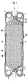
- perforations 2, 3, 4, 5 can be seen in the four corners, via which the two media involved in the heat exchange are guided in a manner known per se for a stack of a plate heat exchanger.
- the plate 1 Between the openings 2, 4 on the one hand and 3, 5 on the other the plate 1 has recesses 6, 7 which are open to the outside. Via these recesses, the plate 1 can be placed on guide rods of a frame which, in a known manner, has a frame plate and a cover plate, between which the stack of plates 1 can be clamped.
- the plate 1 has a profile 8, over which the adjacent plates lie against one another in such a way that flow spaces are formed between adjacent plates, through which the first and second medium can move forward.
- the flow spaces are delimited from the outside by a circumferential seal 10 which, in the case of FIG. 1, is designed and guided such that the medium flowing over the visible side of the plate 1 can move between the openings 2 and 3.
- the openings 4, 5 are sealed off from this medium on the one hand by a circuit 11, 12 and on the other hand by an upstream connection 13, 14 of the seal 10.
- the peripheral seal 10 is now, as can be seen in FIG. 1, designed as a double seal in that a sealing profile 15 facing the media and a sealing profile 16 facing away from the media are guided parallel to one another such that a channel 17 is formed between these two sealing profiles.
- this design has the effect that the pressure existing in the interior of the flow spaces is gradually reduced towards the surroundings of the plate heat exchanger, so that the flow spaces are subjected to very high media pressures can, without leakage can occur to the outside as a result.
- the inner sealing profile 15 and the outer sealing profile 16 are connected to one another several times by bridges 18 along the course of the peripheral seal in order in this way to facilitate the assembly of the seal on the plate 1.
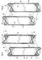
- FIG. 2 shows two plates 19 of the type described with reference to FIG. 1 in an exploded view, as they finally come to lie on one another in the stack of plates.
- Fig. 2 shows that the two identical plates are rotated against each other by 180 °. This results in that, starting from the flow channels 20, 21, 22, 23 formed by the perforations of the plates, the flow space formed between the two plates shown can be fed via the flow channels 20, 21, while that in front of the front plate 19 and the rear plate Plate 19 located flow space is fed via the flow channels 22, 23.
- the plates 19 shown in FIG. 2 show bores 24 of the plate material arranged between the inner sealing profile 15 and the outer sealing profile 16, via which adjacent channels 17 are connected to one another in the stacking direction of the plates.
- this gives the possibility of loading the channels 17 with a third medium, in order to build up the differential pressure between the two sealing profiles via this third medium, with a flushing at the same time a possible leakage can take place via the inner sealing profile 15.
- FIG. 3 shows the two plates 19 according to FIG. 2 in a rear view, from which the embossing of grooves 25, 26 into which the sealing profiles 15, 16 are inserted can be seen.
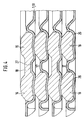
- Fig. 4 shows an enlarged view of a section perpendicular to the plane of the heat exchanger plates 1, 19 in the region of the peripheral seal. It can be seen here how the seals are connected to one another at individual points by bridges 18.
- the bridges have a reduced height compared to the sealing profiles 15, 16 in order to enable channels 17 to run continuously over the entire sealing circumference. So that the bridges 18 do not have to be made too thin, the height of the plate profiling 27 located between the sealing profiles 15, 16 is also reduced in the area of the bridges 18.
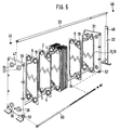
- FIG. 5 shows the overall perspective view of a plate heat exchanger predominantly in an exploded view.
- This shows the plates 19, which are stacked rotated by 180 ° relative to one another, a frame plate 30 and a cover plate 31, as well as the stand 32, from which rods 33, 34 go to the frame plate 30, which the plates 19 pass through their recesses 6 guide and adjust each other.
- the rods 33, 34 are fixed by screws 45, 46 in receiving bores 47, 48 of the frame and cover plate.
- the frame and cover plates form connection openings 35 to 38, the openings 2 to 5 of the plates correspond and thereby connect the channels 20 to 23 (Fig. 2 and 3) to the outside.
- tie rods are used in recesses 51, 52 of the frame and cover plate for the mutual bracing of these plates and thus the package of heat exchanger plates arranged therebetween.
Landscapes
- Engineering & Computer Science (AREA)
- Physics & Mathematics (AREA)
- Thermal Sciences (AREA)
- Mechanical Engineering (AREA)
- General Engineering & Computer Science (AREA)
- Heat-Exchange Devices With Radiators And Conduit Assemblies (AREA)
- Separation By Low-Temperature Treatments (AREA)
- Fuel Cell (AREA)
Abstract
Description
Die Erfindung betrifft einen Plattenwärmeaustauscher mit einer Mehrzahl im wesentlichen rechteckiger, miteinander fluchtender und durch Prägen mit einer Profilierung versehener Platten, die abwechselnd um 180° gegeneinander gedreht unter Anlage der aufeinander zu gerichteten Profilierung benachbarter Platten wenigstens teilweise lösbar zu einem Stapel gespannt sind, wobei die Platten zwischen sich abwechselnd für ein erstes und ein dazu im wesentlichen parallel geführtes zweites Medium durch eine zwischen ihnen entlang ihrem Umfang angeordnete Abdichtung umfangene Strömungsräume bilden, welche über miteinander fluchtende, von in den Eckbereichen der Platten angeordneten Durchbrechungen gebildete Zu- und Abströmöffnungen mit dem jeweiligen Medium beschickbar sind, wobei die Abdichtung zwischen den gegenseitig lösbaren Platten als lösbare Umfangsdichtung ausgebildet ist.The invention relates to a plate heat exchanger with a plurality of substantially rectangular plates that are aligned with one another and provided with embossing with a profiling, which are alternately rotated by 180 ° with respect to one another, with the profiling of adjacent plates facing one another, being at least partially releasably tensioned to form a stack, the Form plates between themselves alternately for a first and a substantially parallel second medium by means of a seal arranged between them along their circumference flow spaces which are aligned with each other and formed by openings arranged in the corner areas of the plates with the respective inflow and outflow openings Medium can be loaded, the seal between the mutually detachable plates being designed as a detachable peripheral seal.
Bei derartigen bekannten Wärmeaustauschern sind die verhältnismäßig dünnwandigen und vielfach auch untereinander formgleichen Platten in einem Rahmen zusammengehalten und zwischen dickeren Endplatten, einer sogenannten Gestellplatte und einer sogenannten Deckelplatte, zu einem Stapel gespannt, wobei Endplatte und/oder Deckelplatte die Anschlüsse für die Medien enthalten, die entlang dem Plattenstapel über Kanäle geführt werden, welche durch die erwähnten Durchbrechungen der Platten in Verbindung mit entsprechender Gestaltung der Abdichtungen gebildet werden. Dabei können die Abdichtungen wenigstens teilweise aus zwischen benachbarten Platten durch Schweißen, Löten, Kleben oder dergleichen befestigten Profilen bestehen, während bei den voneinander lösbaren Platten eine lösbare Umfangsdichtung aus zumindest teilweise elastischem Material verwendet wird.In such known heat exchangers, the relatively thin-walled and often also mutually identical plates are held together in a frame and stretched into a stack between thicker end plates, a so-called frame plate and a so-called cover plate, the end plate and / or cover plate containing the connections for the media which along the Plate stacks are guided over channels, which are formed by the above-mentioned openings in the plates in connection with a corresponding design of the seals. The seals can at least partially consist of profiles fastened between adjacent plates by welding, soldering, gluing or the like, while a releasable peripheral seal made of at least partially elastic material is used in the mutually detachable plates.
Die zwischen den Platten gebildeten Strömungsräume sind durch das erste und zweite Medium druckbeaufschlagt. Dabei findet jedoch die mögliche Höhe einer derartigen Druckbeaufschlagung durch die Belastbarkeit der wenigstens teilweise aus elastischem Material bestehenden Umfangsdichtungen ihre Grenze. Man kann zwar den Plattenstapel durch entsprechende hohe Vorspannung zwischen Gestell- und Deckelplatte stark zusammenpressen. Auch hier ist jedoch eine Grenze wieder dann gegeben, wenn das Material der Umfangsdichtungen zu stark verpreßt und damit verquetscht würde.The flow spaces formed between the plates are pressurized by the first and second medium. However, the possible amount of such pressurization is limited by the resilience of the peripheral seals, which are at least partially made of elastic material. It is true that the stack of plates can be strongly pressed together by a correspondingly high prestress between the frame and cover plate. Here too, however, there is a limit again if the material of the peripheral seals is pressed too hard and thus squeezed.
Will man daher unter sehr hohem Druck stehende Medien dem Wärmeaustausch zuführen, muß man auf andere Formen von Wärmeaustauschern ausweichen, beispielsweise Röhrenwärmeaustauscher. Solche Röhrenwärmeaustauscher sind jedoch vergleichbar wesentlich kostspieliger und unhandlicher als Plattenwärmeaustauscher.Therefore, if you want to supply media under very high pressure to the heat exchange, you have to switch to other forms of heat exchangers, for example tubular heat exchangers. However, such tube heat exchangers are comparatively much more expensive and unwieldy than plate heat exchangers.
Aufgabe der Erfindung ist es daher, einen Plattenwärmeaustauscher der eingangs genannten Art auf einfache Weise derart abzuändern bzw. zu ergänzen, daß er eine gegenüber dem Bisherigen wesentlich höhere Druckbelastbarkeit durch die Medien erlaubt bei vergleichsweise nur mäßiger Erhöhung der Gestehungskosten.The object of the invention is therefore to modify or supplement a plate heat exchanger of the type mentioned in a simple manner in such a way that it opposes one the previous much higher pressure resistance by the media allowed with a comparatively moderate increase in the cost price.
Diese Aufgabe ist ausgehend von einem Plattenwärmeaustauscher der eingangs genannten Art erfindungsgemäß dadurch gelöst, daß die Umfangsdichtung wenigstens über einen Teil ihrer Längserstreckung als mindestens zweireihige Mehrfachdichtung aus mit Abstand zueinander angeordneten Dichtungsprofilen ausgebildet ist.This object is achieved on the basis of a plate heat exchanger of the type mentioned at the outset in that the peripheral seal is formed at least over part of its longitudinal extent as an at least two-row multiple seal from sealing profiles arranged at a distance from one another.
Diese erfindungsgemäße Maßnahme hat die Wirkung, daß zwischen benachbarten Profilen der Umfangsdichtungen ein schmaler, beidseits abgedichteter Kanal entsteht. Nunmehr kann beispielsweise im Falle einer Doppeldichtung bei Leckage der medienzugewandten Dichtung sich in dem Kanal ein Zwischendruck aufbauen, der einerseits von der medienabgewandten Dichtung mit Sicherheit leckagefrei getragen werden kann, während er für die medienzugewandte Dichtung eine Stütz- und Gegendruckwirkung ergibt. Insgesamt wird also der Mediendruck stufenweise hin zum Umgebungsdruck, normalerweise Atmosphärendruck, abgebaut, wobei jedes der zueinander parallelen Dichtungsprofile nur einen Teil der Differenz zwischen Mediendruck und Umgebungsdruck zu tragen hat.This measure according to the invention has the effect of creating a narrow channel sealed on both sides between adjacent profiles of the peripheral seals. Now, for example, in the case of a double seal in the event of a leak in the seal facing the media, an intermediate pressure can build up in the channel, which on the one hand can be safely carried without leakage by the seal facing away from the media, while providing a support and counterpressure effect for the seal facing the media. Overall, the media pressure is gradually reduced to ambient pressure, usually atmospheric pressure, with each of the sealing profiles parallel to one another only having to bear part of the difference between media pressure and ambient pressure.
Diese Verhältnisse gelten sinngemäß entsprechend für Mehrfachdichtungen mit drei oder mehr zueinander parallelen Dichtungsprofilen.These relationships apply mutatis mutandis to multiple seals with three or more mutually parallel sealing profiles.
Nach einer Ausführungs- und Anwendungsform der Erfindung kann die Mehrfachdichtung jeweils zwischen Strömungsraum und den Durchbrechungen der zugeordneten Platte vorgesehen sein, die ohne Verbindung mit dem Strömungsraum lediglich dem Medientransfer zu den dem Strömungsraum benachbarten Strömungsräumen dienen. Diese üblicherweise vorhandene Dichtungszone ist eine der kritischen, wenn nicht überhaupt die kritische Dichtungszone zwischen zwei benachbarten Platten, da die Platte hier auf der dichtungsabgewandten Seite in der Regel keine Abstützung der Dichtungszone gegenüber der benachbarten Platte hat, denn dort muß von der angesprochenen Durchbrechung ausgehend der benachbarte Strömungsraum mit dem zugeordneten Medium beschickt bzw. von diesem Medium entsorgt werden. Durch dieses Fehlen einer Abstützung kann aber an der genannten Stelle die dortige Dichtung nicht so stark vorgespannt werden wie die übrigen Teile der Umfangsdichtung, so daß es hier bei hohen Mediendrücken zuerst zu einer Leckage kommt.According to one embodiment and application form of the invention, the multiple seal can in each case between the flow space and the openings of the associated plate can be provided, which, without connection to the flow space, only serve to transfer media to the flow spaces adjacent to the flow space. This usually existing sealing zone is one of the critical, if not the critical, sealing zone between two adjacent plates, since the plate here on the side facing away from the seal generally has no support for the sealing zone with respect to the adjacent plate, because there the opening must be based on the opening mentioned Adjacent flow space are loaded with the assigned medium or disposed of by this medium. Due to this lack of support, the seal there cannot be pre-stressed as much as the other parts of the circumferential seal, so that there is a leakage at high media pressures.
Nach einer anderen Ausführungsform der Erfindung kann vorgesehen sein, daß die gesamte Umfangsdichtung als Mehrfachdichtung ausgebildet ist. Damit ergibt sich nun die Möglichkeit einer erheblichen Steigerung der anwendbaren Mediendrücke.According to another embodiment of the invention, it can be provided that the entire peripheral seal is designed as a multiple seal. This now gives the possibility of a significant increase in the applicable media pressures.
Ausgehend von einer gleichbleibenden Wärmeaustauschfläche der Platten bedeutet zwar die Verdoppelung oder gar Verdreifachung, Vervierfachung etc. der Umfangsdichtung eine Vergrößerung der Platten, es müssen die Gestell- und Deckelplatte entsprechend vergrößert und stärker dimensioniert werden und es müssen stärkere bzw. zahlreichere Spannmittel für den Plattenstapel vorgesehen werden. Diese Aufwendungen halten sich jedoch immer noch in überschaubaren und wirtschaftlich tragbaren Grenzen verglichen beispielsweise mit der eingangs genannten Alternative einer anderen Wärmeaustauscherart in Form eines Röhrenwärmeaustauschers.Starting from a constant heat exchange surface of the plates, doubling or even tripling, quadrupling, etc. of the peripheral seal means an enlargement of the plates, the frame and cover plates have to be enlarged and dimensioned accordingly, and stronger or more numerous clamping means must be provided for the plate stack will. However, these expenses are still manageable and economically acceptable limits compared, for example, with the alternative mentioned at the beginning of another type of heat exchanger in the form of a tubular heat exchanger.
Zweckmäßig ist es im Rahmen der Erfindung, daß in an sich bekannter Weise die Profile der Umfangsdichtungen in aus den Platten geprägte Dichtungsnuten eingesetzt sind, deren Tiefe einem Teil der Höhe des jeweiligen Dichtungsprofils entspricht. Hier ragt dann das Plattenprofil mit einer Erhebung, die nicht über den Umfang durchgehend sein muß, in den jeweils zwischen benachbarten Dichtungsprofilen gebildeten Kanal, um die Dichtungsprofile gegenüber dem Kanal zu stützen.It is expedient within the scope of the invention that the profiles of the peripheral seals are inserted in sealing grooves embossed from the plates, the depth of which corresponds to part of the height of the respective sealing profile. Here then the plate profile projects with an elevation, which does not have to be continuous over the circumference, into the channel formed in each case between adjacent sealing profiles in order to support the sealing profiles with respect to the channel.
Vorteilhaft ist es ferner, daß benachbarte Profile der Mehrfachdichtung an einzelnen, gegenseitig beabstandeten Stellen durch quer zu ihrer Längserstreckung verlaufende Brücken aus dem Material der Umfangsdichtung einstückig miteinander verbunden sind. Hierdurch ergibt sich insbesondere bezüglich der Handhabung der Mehrfachdichtung beim Einbau in die Dichtungsnuten eine wesentliche Erleichterung.It is also advantageous that adjacent profiles of the multiple seal are integrally connected to one another at individual, mutually spaced locations by bridges made of the material of the peripheral seal and extending transversely to their longitudinal extension. This results in a significant relief, particularly with regard to the handling of the multiple seal when it is installed in the sealing grooves.
Bei dieser Bauform ist es zweckmäßig, daß die Höhe der Brücken derart gegenüber der der Dichtungsprofile reduziert ist, daß zwischen den Dichtungsprofilen der Mehrfachdichtung ein in deren Längserstreckung durchgehender Kanal gebildet ist. Dadurch ist ein Druckausgleich über die gesamte Länge des Kanales gewährleistet, so daß sich nicht beidseitig einer Brücke unterschiedliche Drücke aufbauen können.With this design, it is expedient that the height of the bridges is reduced in comparison to that of the sealing profiles in such a way that a channel extending in the longitudinal direction thereof is formed between the sealing profiles of the multiple seal. This ensures pressure equalization over the entire length of the channel, so that different pressures cannot build up on both sides of a bridge.
In diesem Zusammenhang ist es ferner zweckmäßig, daß die zwischen zwei benachbarten Dichtungsnuten bestehende Plattenprofilierung an den die Brücke aufweisenden Stellen in ihrer Höhe reduziert ist. Dadurch ist eine zu dünnwandige Gestaltung der Brücken verhindert.In this context it is furthermore expedient that the height of the plate profiling existing between two adjacent sealing grooves is reduced at the points having the bridge. This prevents the bridges from being too thin-walled.
In weiterer Ausbildung des Erfindungsgedankens kann vorgesehen sein, daß die Platten im Bereich der zwischen benachbarten Profilen der Umfangsdichtung gebildeten Kanäle Bohrungen aufweisen, über die die Dichtungskanäle mit einem unter Überdruck stehenden dritten Medium beschickbar sind, wobei die Höhe des Überdruckes zwischen der des ersten und zweiten Mediums einerseits und der der Umgebung des Plattenwärmeaustauschers andererseits liegt.In a further development of the inventive concept, it can be provided that the plates have holes in the region of the channels formed between adjacent profiles of the peripheral seal, through which the sealing channels can be charged with a pressurized third medium, the amount of the pressure between that of the first and second Medium on the one hand and the environment of the plate heat exchanger on the other.
Diese Gestaltung gibt die Möglichkeit, die zwischen den Umfangsdichtungen gebildeten Kanäle mit einem Sperrmedium, beispielsweise einer Flüssigkeit oder einem Gas zu beschicken, wodurch verhindert ist, daß in die Kanäle überhaupt Mengen des ersten oder zweiten Mediums gelangen können. Auf diese Weise ist es aber insbesondere auch möglich, einen aseptischen Plattenwärmeaustauscher zu gestalten. Sollte andererseits trotzdem einmal etwas vom ersten oder zweiten Medium in einen der Kanäle gelangen, so kann dieses Leckagematerial sofort leicht durch das dritte Medium weggespült werden.This design enables the channels formed between the circumferential seals to be charged with a barrier medium, for example a liquid or a gas, which prevents quantities of the first or second medium from getting into the channels at all. In this way it is also possible, in particular, to design an aseptic plate heat exchanger. On the other hand, should anything of the first or second medium get into one of the channels, this leakage material can be easily washed away immediately by the third medium.
In Ausgestaltung dieser Möglichkeit ist es speziell im Falle einer Mehrfachdichtung in Form einer Doppeldichtung zweckmäßig, daß die Höhe des Überdruckes des dritten Mediums etwa mittig zwischen der des ersten und zweiten Mediums einerseits und der der Umgebung des Plattenwärmeaustauschers andererseits liegt.In an embodiment of this possibility, it is particularly expedient in the case of a multiple seal in the form of a double seal that the height of the excess pressure of the third medium is approximately midway between that of the first and second medium on the one hand and that of the surroundings of the plate heat exchanger on the other.
Wird in diesem Zusammenhang von einem Plattenwärmeaustauscher ausgegangen, bei dem die Platten in einem Rahmen gestellt zwischen einer Gestellplatte und einer Deckelplatte des Rahmens fluchtend geführt lösbar zu einem Stapel gespannt sind, so kann schließlich vorgesehen sein, daß Gestellplatte und/oder Deckelplatte mit den Kanälen korrespondierende Anschlußverbindungen zur Zuleitung und gegebenenfalls Ableitung des dritten Mediums aufweisen.Is assumed in this context from a plate heat exchanger, in which the plates placed in a frame between a frame plate and a cover plate of the frame are guided in a releasably tensioned manner to form a stack, it can finally be provided that the frame plate and / or cover plate correspond to the channels Have connection connections to the feed line and, if necessary, discharge line of the third medium.
Weitere Merkmale und Einzelheiten der Erfindung ergeben sich aus der nachfolgenden Beschreibung von Ausführungsformen anhand der Zeichnung. In der Zeichnung zeigen:
- Fig. 1
- Die Frontalansicht einer lösbaren Wärmeaustauscherplatte;
- Fig. 2
- zwei benachbarte Wärmeaustauscherplatten gemäß Fig. 1 in Explosionsdarstellung;
- Fig. 3
- die Rückansicht der Wärmeaustauscherplatten gemäß Fig. 2,
- Fig. 4
- die Schnittansicht durch den Dichtungsbereich mehrerer aufeinander gestapelter Wärmeaustauscherplatten gemäß Fig. 2 und 3 sowie
- Fig. 5
- die perspektivische Ansicht eines Wärmeaustauschers mit Platten gemäß Fig. 1 bis 4, teilweise in Explosionsdarstellung.
- Fig. 1
- The frontal view of a detachable heat exchanger plate;
- Fig. 2
- two adjacent heat exchanger plates according to Figure 1 in an exploded view.
- Fig. 3
- the rear view of the heat exchanger plates according to FIG. 2,
- Fig. 4
- the sectional view through the sealing region of a plurality of heat exchanger plates stacked on top of one another according to FIGS. 2 and 3 and
- Fig. 5
- the perspective view of a heat exchanger with plates according to FIGS. 1 to 4, partially in an exploded view.
Bei der in Fig. 1 dargestellten Wärmeaustauscherplatte 1 erkennt man in den vier Ecken Durchbrechungen 2, 3, 4, 5, über die in an sich bekannter Weise bei einem Stapel eines Plattenwärmeaustauschers die beiden am Wärmeaustausch beteiligten Medien geführt werden. Zwischen den Durchbrechungen 2, 4 einerseits und 3, 5 andererseits weist die Platte 1 Ausnehmungen 6, 7 auf, die nach außen offen sind. Über diese Ausnehmungen ist die Platte 1 auf Führungsstangen eines Rahmengestells setzbar, das in bekannter Weise eine Gestellplatte und eine Deckelplatte aufweist, zwischen denen der Stapel von Platten 1 zusammenspannbar ist.In the
Im mittleren Bereich weist die Platte 1 eine Profilierung 8 auf, über die benachbarte Platten aneinander liegen derart, daß zwischen benachbarten Platten Strömungsräume gebildet werden, durch die erstes und zweites Medium sich voranbewegen können.In the central area, the
Die Strömungsräume sind nach außen abgegrenzt durch eine Umfangsdichtung 10, die im Falle der Fig. 1 so ausgebildet und geführt ist, daß das über die sichtbare Seite der Platte 1 strömende Medium sich zwischen den Durchbrechungen 2 und 3 bewegen kann. Demgegenüber sind die Durchbrechungen 4, 5 gegenüber diesem Medium einmal durch einen Umlauf 11, 12 und zum anderen durch eine vorgeschaltete Verbindung 13, 14 der Dichtung 10 abgeschottet.The flow spaces are delimited from the outside by a
Die Umfangsdichtung 10 ist nun, wie aus Fig. 1 ersichtlich, als Doppeldichtung ausgebildet, indem ein medienzugewandtes Dichtungsprofil 15 und ein medienabgewandtes Dichtungsprofil 16 parallel zueinander geführt sind derart, daß zwischen diesen beiden Dichtungsprofilen ein Kanal 17 entsteht. Diese Ausbildung hat, wie bereits geschildert, die Wirkung, daß der im inneren der Strömungsräume bestehende Druck stufenweise zur Umgebung des Plattenwärmeaustauschers hin abgebaut wird, so daß die Strömungsräume mit sehr hohen Mediendrücken beaufschlagt werden können, ohne daß nach außen im Ergebnis eine Leckage auftreten kann.The
Wie aus Fig. 1 außerdem ersichtlich, sind inneres Dichtungsprofil 15 und äußeres Dichtungsprofil 16 entlang dem Verlauf der Umfangsdichtung mehrfach durch Brücken 18 miteinander verbunden, um auf diese Art und Weise die Montage der Dichtung auf der Platte 1 zu erleichtern.As can also be seen from FIG. 1, the
Fig. 2 zeigt zwei Platten 19 der anhand der Fig. 1 geschilderten Art in Explosionsdarstellung so, wie sie schlußendlich im Plattenstapel aufeinander zu liegen kommen. Fig. 2 läßt erkennen, daß die beiden an sich gleichen Platten gegeneinander um 180° gedreht sind. Dadurch ergibt sich, daß ausgehend von den durch die Durchbrechnungen der Platten gebildeten Strömungskanälen 20, 21, 22, 23 einmal der zwischen den beiden dargestellten Platten gebildete Strömungsraum über die Strömungskanäle 20, 21 beschickbar ist, während der vor der vorderen Platte 19 und der hinteren Platte 19 gelegene Strömungsraum über die Strömungskanäle 22, 23 beschickt wird.FIG. 2 shows two
In Abweichung zur Plattendarstellung gemäß Fig. 1 zeigen die in Fig. 2 dargestellten Platten 19 zwischen innerem Dichtungsprofil 15 und äußerem Dichtungsprofil 16 angeordnete Bohrungen 24 des Plattenmaterials, über die in Stapelrichtung der Platten benachbarte Kanäle 17 miteinander verbunden sind. Dies gibt in der bereits beschriebenen Weise die Möglichkeit, die Kanäle 17 mit einem dritten Medium zu beschicken, um über dieses dritte Medium den Differenzdruck zwischen den beiden Dichtungsprofilen aufzubauen, wobei gleichzeitig eine Spülung bezüglich einer eventuellen Leckage über das innere Dichtungsprofil 15 erfolgen kann.In a departure from the plate representation according to FIG. 1, the
Fig. 3 zeigt die beiden Platten 19 gemäß Fig. 2 in Rückansicht, woraus die Prägung von Nuten 25, 26 ersichtlich ist, in die die Dichtungsprofile 15, 16 eingesetzt sind.FIG. 3 shows the two
Fig. 4 zeigt in vergrößerter Darstellung einen zur Ebene der Wärmeaustauscherplatten 1, 19 senkrechten Schnitt im Bereich der Umfangsdichtung. Hier ist ersichtlich, wie die Dichtungen an einzelnen Stellen durch Brücken 18 miteinander verbunden sind. Die Brücken haben eine gegenüber den Dichtungsprofilen 15, 16 reduzierte Höhe, um über den gesamten Dichtungsumfang durchgehende Kanäle 17 zu ermöglichen. Damit die Brücken 18 nicht zu dünn ausgebildet werden müssen, ist im Bereich der Brücken 18 außerdem die zwischen den Dichtungsprofilen 15, 16 gelegene Plattenprofilierung 27 ebenfalls in ihrer Höhe reduziert.Fig. 4 shows an enlarged view of a section perpendicular to the plane of the
Fig. 5 zeigt schließlich in Anlehnung an Fig. 2 und 3 die perspektivische Gesamtansicht eines Plattenwärmeaustauschers vorwiegend in Explosionsdarstellung. Bei dieser sind erkennbar die Platten 19, die um 180° gegeneinander gedreht gestapelt sind, eine Gestellplatte 30 und eine Deckelplatte 31, sowie der Ständer 32, von dem ausgehend Stangen 33, 34 zur Gestellplatte 30 gehen, die die Platten 19 über deren Ausnehmungen 6 führen und gegenseitig justieren. Die Stangen 33, 34 sind über Schrauben 45, 46 in Aufnahmebohrungen 47, 48 von Gestell- und Deckelplatte festgelegt.Finally, based on FIGS. 2 and 3, FIG. 5 shows the overall perspective view of a plate heat exchanger predominantly in an exploded view. This shows the
Die Gestell- und Deckelplatten bilden Anschlußöffnungen 35 bis 38, die mit den Durchbrechungen 2 bis 5 der Platten korrespondieren und dadurch die Kanäle 20 bis 23 (Fig. 2 und 3) nach außen verbinden.The frame and cover plates form connection openings 35 to 38, the
Mit 50 ist eine von mehreren Spannstangen bezeichnet, die in Ausnehmungen 51, 52 von Gestell und Deckelplatte eingesetzt der gegenseitigen Verspannung dieser Platten und damit des dazwischen angeordneten Paketes von Wärmeaustauscherplatten dienen.With 50 one of several tie rods is designated, which are used in
Claims (10)
dadurch gekennzeichnet,
daß die Umfangsdichtung (10) wenigstens über einen Teil ihrer Längserstreckung als mindestens zweireihige Mehrfachdichtung aus mit Abstand zueinander angeordneten Dichtungsprofilen (15, 16) ausgebildet ist.Plate heat exchangers with a plurality of substantially rectangular plates which are aligned and are provided with a profiling by embossing and which are alternately rotated by 180 ° relative to one another and at least partially releasably tensioned to form a stack by contacting the profiling of adjacent plates, the plates alternating between them for a first and an essentially parallel second medium, by means of a seal arranged between them along their circumference, form extensive flow spaces, which can be filled with the respective medium via aligned inflow and outflow openings formed by openings in the corner regions of the plates, wherein the seal between the mutually detachable plates is designed as a detachable peripheral seal,
characterized,
that the circumferential seal (10) is formed at least over part of its longitudinal extent as an at least double-row multiple seal made of spaced-apart sealing profiles (15, 16).
dadurch gekennzeichnet,
daß die Mehrfachdichtung (13, 14) jeweils zwischen Strömungsraum und den Durchbrechungen (4, 5) der zugeordneten Platte (1) vorgesehen ist, die ohne Verbindung mit dem Strömungsraum lediglich dem Medientransfer zu den dem Strömungsraum benachbarten Strömungsräumen dienen.Plate heat exchanger according to claim 1,
characterized,
that the multiple seal (13, 14) is in each case provided between the flow space and the openings (4, 5) of the associated plate (1), which, without being connected to the flow space, only serve to transfer media to the flow spaces adjacent to the flow space.
dadurch gekennzeichnet,
daß die gesamte Umfangsdichtung (10) als Mehrfachdichtung ausgebildet ist.Plate heat exchanger according to claim 1,
characterized,
that the entire peripheral seal (10) is designed as a multiple seal.
dadurch gekennzeichnet,
daß die Profile der Umfangsdichtung (15, 16) in aus den Platten (1, 19) geprägte Dichtungsnuten (25, 26) eingesetzt sind, deren Tiefe einem Teil der Höhe des jeweiligen Dichtungsprofils entspricht.Plate heat exchanger according to one of claims 1 to 3,
characterized,
that the profiles of the peripheral seal (15, 16) are inserted into sealing grooves (25, 26) embossed from the plates (1, 19), the depth of which corresponds to part of the height of the respective sealing profile.
dadurch gekennzeichnet,
daß benachbarte Profile (15, 16) der Mehrfachdichtung (10) an einzelnen, gegenseitig beabstandeten Stellen durch quer zu ihrer Längserstreckung verlaufende Brücken (18) aus dem Material der Umfangsdichtung einstückig miteinander verbunden sind.Plate heat exchanger according to one of the preceding claims,
characterized,
that adjacent profiles (15, 16) of the multiple seal (10) are integrally connected to one another at individual, mutually spaced locations by bridges (18) made of the material of the peripheral seal and extending transversely to their longitudinal extent.
dadurch gekennzeichnet,
daß die Höhe der Brücken (18) derart gegenüber der der Dichtungsprofile (15, 16) reduziert ist, daß zwischen den Dichtungsprofilen der Mehrfachdichtung (10) ein in deren Längserstreckung durchgehender Kanal (17) gebildet ist.Plate heat exchanger according to claim 5,
characterized,
that the height of the bridges (18) is so reduced compared to that of the sealing profiles (15, 16) that between the Sealing profiles of the multiple seal (10) is formed in its longitudinal extension continuous channel (17).
dadurch gekennzeichnet,
daß die zwischen zwei benachbarten Dichtungsnuten (25, 26) bestehende Plattenprofilierung (27) an den die Brücken aufweisenden Stellen in ihrer Höhe reduziert ist.Plate heat exchanger according to claim 5 or 6,
characterized,
that the existing between two adjacent sealing grooves (25, 26) plate profile (27) is reduced in height at the locations having the bridges.
dadurch gekennzeichnet,
daß die Platten (19) im Bereich der zwischen benachbarten Profilen der Umfangsdichtung (15, 16) gebildeten Kanäle (17) Bohrungen (24) aufweisen, über die die Dichtungskanäle mit einem unter Überdruck stehenden drittem Medium beschickbar sind, wobei die Höhe des Überdruckes zwischen der des ersten und zweiten Mediums einerseits und der der Umgebung des Plattenwärmeaustauschers andererseits liegt.Plate heat exchanger according to one of the preceding claims,
characterized,
that the plates (19) in the region between the adjacent profiles of the peripheral seal (15, 16) formed channels (17) have bores (24) through which the sealing channels can be charged with a third medium under pressure, the amount of pressure between that of the first and second medium on the one hand and that of the surroundings of the plate heat exchanger on the other.
dadurch gekennzeichnet,
daß die Höhe des Überdruckes des dritten Mediums etwa mittig zwischen der des ersten und zweiten Mediums einerseits und der der Umgebung des Plattenwärmeaustauscher andererseits liegt.Plate heat exchanger according to claim 8,
characterized,
that the height of the overpressure of the third medium is approximately midway between that of the first and second medium on the one hand and that of the surroundings of the plate heat exchanger on the other.
dadurch gekennzeichnet,
daß Gestellplatte (30) und/oder Deckelplatte (31) mit den Kanälen (17) korrespondierende Anschlußverbindungen zur Zuleitung und gegebenenfalls Ableitung des dritten Mediums aufweisen.Plate heat exchanger according to claim 8 or 9, wherein the plates placed in a frame between a frame plate and a cover plate of the frame are aligned and releasably tensioned to form a stack,
characterized,
that the frame plate (30) and / or cover plate (31) with the channels (17) have corresponding connection connections for supplying and, if appropriate, discharging the third medium.
Applications Claiming Priority (2)
| Application Number | Priority Date | Filing Date | Title |
|---|---|---|---|
| DE4037969 | 1990-11-29 | ||
| DE4037969A DE4037969A1 (en) | 1990-11-29 | 1990-11-29 | HEAT EXCHANGER |
Publications (2)
| Publication Number | Publication Date |
|---|---|
| EP0487931A1 true EP0487931A1 (en) | 1992-06-03 |
| EP0487931B1 EP0487931B1 (en) | 1995-03-01 |
Family
ID=6419148
Family Applications (1)
| Application Number | Title | Priority Date | Filing Date |
|---|---|---|---|
| EP91118684A Revoked EP0487931B1 (en) | 1990-11-29 | 1991-11-02 | Plate heat exchanger |
Country Status (6)
| Country | Link |
|---|---|
| US (1) | US5193612A (en) |
| EP (1) | EP0487931B1 (en) |
| JP (1) | JPH04273994A (en) |
| AT (1) | ATE119270T1 (en) |
| DE (2) | DE4037969A1 (en) |
| DK (1) | DK0487931T3 (en) |
Cited By (4)
| Publication number | Priority date | Publication date | Assignee | Title |
|---|---|---|---|---|
| EP0600189A1 (en) * | 1992-11-20 | 1994-06-08 | BDAG Balcke-Dürr Aktiengesellschaft | Plate heat exchanger |
| DE19617396A1 (en) * | 1996-05-02 | 1997-11-06 | Dornier Gmbh | Flow module |
| FR2910607A1 (en) * | 2006-12-21 | 2008-06-27 | Alfa Laval Vicard Soc Par Acti | Heat exchanger, has rectangle parallelepiped shaped spacer compressed and arranged in contact with plates, where spacer having thickness equal to thickness of sealing joint, before compression, and forms protrusion of sealing joint |
| CN111412783A (en) * | 2020-03-30 | 2020-07-14 | 浙江大学 | A power battery plate heat exchanger and its assembly processing device |
Families Citing this family (29)
| Publication number | Priority date | Publication date | Assignee | Title |
|---|---|---|---|---|
| SE505225C2 (en) * | 1993-02-19 | 1997-07-21 | Alfa Laval Thermal Ab | Plate heat exchanger and plate for this |
| US5494301A (en) * | 1993-04-20 | 1996-02-27 | W. L. Gore & Associates, Inc. | Wrapped composite gasket material |
| DE4431413C2 (en) * | 1994-08-24 | 2002-10-10 | Rehberg Michael | Plate heat exchangers for liquid and gaseous media |
| DE19519740B4 (en) * | 1995-06-02 | 2005-04-21 | Mann + Hummel Gmbh | heat exchangers |
| SE9502135D0 (en) * | 1995-06-13 | 1995-06-13 | Tetra Laval Holdings & Finance | plate heat exchangers |
| SE521916C2 (en) * | 1997-02-25 | 2003-12-16 | Ep Technology Ab | Flat heat exchanger with leakage emissions |
| DK174409B1 (en) * | 1998-01-12 | 2003-02-17 | Apv Heat Exchanger As | Heat exchanger plate with reinforced edge design |
| SE518211C2 (en) * | 1999-12-15 | 2002-09-10 | Swep Int Ab | Hot water heater comprising a plate heat exchanger and a storage container |
| DE10029999A1 (en) * | 2000-06-17 | 2002-01-03 | Otto Thermotech Gmbh | Plate heat exchanger of sealed type has seal with bottom approximately same shape as sealing groove base, sealing surface approximately same shape as base of adjacent plate |
| DE10035939A1 (en) * | 2000-07-21 | 2002-02-07 | Bosch Gmbh Robert | Heat transfer device |
| SE522500C2 (en) * | 2002-09-17 | 2004-02-10 | Valeo Engine Cooling Ab | Arrangement with plate heat exchanger is for connection to system in which exchanger is to be installed and involves exchanger conventionally formed with reciprocal parallel plates comprising plate packet |
| WO2005012820A1 (en) | 2003-08-01 | 2005-02-10 | Behr Gmbh & Co. Kg | Heat exchanger and method for the production thereof |
| US20070169916A1 (en) * | 2006-01-20 | 2007-07-26 | Wand Steven M | Double-wall, vented heat exchanger |
| WO2011013950A2 (en) * | 2009-07-27 | 2011-02-03 | 한국델파이주식회사 | Plate heat exchanger |
| US9596785B2 (en) * | 2010-03-22 | 2017-03-14 | Pratt & Whitney Canada Corp. | Heat exchanger |
| SE535209C2 (en) * | 2010-06-15 | 2012-05-22 | Alfa Laval Corp Ab | Corrosion resistant plate heat exchanger with tantalum coating |
| DE102010037152B4 (en) * | 2010-08-25 | 2022-08-25 | Gea Wtt Gmbh | Sealed plate heat exchanger |
| EP2757339B1 (en) * | 2011-09-14 | 2018-05-02 | Hisaka Works, Ltd. | Plate heat exchanger |
| CN103673696A (en) * | 2013-12-26 | 2014-03-26 | 上海艾克森集团有限公司 | Improved semi-welded plate heat exchanger |
| DE102014014070A1 (en) | 2014-09-29 | 2016-03-31 | Forschungszentrum Jülich GmbH | Device for controlled heat transfer to and from a component |
| CN106017192B (en) * | 2015-04-29 | 2018-05-25 | 于仁麟 | A kind of plate heat exchanger of corrugation density variation |
| JP6911469B2 (en) * | 2017-03-31 | 2021-07-28 | 株式会社Ihi | Heat treatment equipment |
| US10876794B2 (en) * | 2017-06-12 | 2020-12-29 | Ingersoll-Rand Industrial U.S., Inc. | Gasketed plate and shell heat exchanger |
| CN109141095A (en) * | 2018-09-30 | 2019-01-04 | 浙江华立智能装备股份有限公司 | A kind of plate heat exchanger of good airproof performance |
| DK180145B1 (en) * | 2018-11-27 | 2020-06-25 | Danfoss As Intellectual Property | Plate heat exchanger |
| CN110779360A (en) * | 2019-10-30 | 2020-02-11 | 广西华银铝业有限公司 | A Heat Exchanger Convenient for Online Pickling |
| LT4083561T (en) * | 2021-04-27 | 2023-11-27 | Alfa Laval Corporate Ab | Heat transfer plate and gasket |
| US12135176B2 (en) * | 2021-07-20 | 2024-11-05 | WCR Inc. | Plate heat exchanger gasket |
| JPWO2023042919A1 (en) * | 2021-09-17 | 2023-03-23 |
Citations (3)
| Publication number | Priority date | Publication date | Assignee | Title |
|---|---|---|---|---|
| US2777674A (en) * | 1953-05-29 | 1957-01-15 | Creamery Package Mfg Co | Plate type heat exchanger |
| FR2355265A2 (en) * | 1976-06-14 | 1978-01-13 | Chaffoteaux Et Maury | Leakproof heat exchanger system - using two elastic rings to ensure that any leaks do not mix inside |
| GB2141814A (en) * | 1983-06-20 | 1985-01-03 | Apv Int Ltd | Improvements in plate heat exchangers |
Family Cites Families (17)
| Publication number | Priority date | Publication date | Assignee | Title |
|---|---|---|---|---|
| DE86728C (en) * | ||||
| DE905982C (en) * | 1948-10-05 | 1954-03-08 | Deutsche Edelstahlwerke Ag | Purge or blow-off pipes |
| DE905981C (en) * | 1952-04-10 | 1954-03-08 | Ahlborn E Ag | Plate-shaped heat exchanger |
| GB842962A (en) * | 1957-10-09 | 1960-08-04 | Silkeborg Maskinfabrik As | A plate heat exchanging apparatus |
| GB894462A (en) * | 1959-05-27 | 1962-04-26 | Separator Ab | A method for sterilization of heat exchangers and a heat exchanger adapted therefor |
| GB1024977A (en) * | 1963-07-11 | 1966-04-06 | Apv Co Ltd | Improvements in or relating to plate type heat exchangers |
| SE302468B (en) * | 1965-12-29 | 1968-07-22 | Alfa Laval Ab | |
| FR2319101A1 (en) * | 1975-07-22 | 1977-02-18 | Chausson Usines Sa | RADIATOR WITH TANKS AND MECHANICALLY ASSEMBLED TUBES |
| DK417676A (en) * | 1976-09-16 | 1978-03-17 | Danske Mejeriers Maskinfabrik | HEAT EXCHANGE PLATE FOR HEAT EXCHANGERS |
| SE424906B (en) * | 1976-10-14 | 1982-08-16 | Hisaka Works Ltd | PACKAGING FOR PLASTIC EXCHANGERS |
| GB2057668A (en) * | 1979-08-13 | 1981-04-01 | Apv Co Ltd | Gasketing of plate heat transfer apparatus |
| GB2114248B (en) * | 1981-01-15 | 1985-03-06 | Ava Int Corp | Sealed conduit joint |
| GB2117890A (en) * | 1982-04-05 | 1983-10-19 | Apv Company Limited The | Gasketing of heat transfer plates |
| DE3300523A1 (en) * | 1983-01-10 | 1984-07-12 | Funke Wärmeaustauscher Apparatebau KG, 3212 Gronau | Plate heat exchanger |
| DE3544588A1 (en) * | 1985-12-17 | 1987-06-25 | Bruss Dichtungstechnik | Elastomeric seal for heat exchangers |
| DE3903084A1 (en) * | 1989-02-02 | 1990-08-09 | Bergfeld & Heider Gmbh & Co Kg | Plate heat exchanger |
| DE9101880U1 (en) * | 1991-02-19 | 1991-05-08 | Transformatoren- und Röntgenwerk GmbH, O-8030 Dresden | Sealing element for electrical devices filled with insulating liquid |
-
1990
- 1990-11-29 DE DE4037969A patent/DE4037969A1/en not_active Withdrawn
-
1991
- 1991-11-02 DK DK91118684.9T patent/DK0487931T3/en active
- 1991-11-02 DE DE59104777T patent/DE59104777D1/en not_active Revoked
- 1991-11-02 AT AT91118684T patent/ATE119270T1/en not_active IP Right Cessation
- 1991-11-02 EP EP91118684A patent/EP0487931B1/en not_active Revoked
- 1991-11-29 US US07/800,486 patent/US5193612A/en not_active Expired - Fee Related
- 1991-11-29 JP JP3315084A patent/JPH04273994A/en active Pending
Patent Citations (3)
| Publication number | Priority date | Publication date | Assignee | Title |
|---|---|---|---|---|
| US2777674A (en) * | 1953-05-29 | 1957-01-15 | Creamery Package Mfg Co | Plate type heat exchanger |
| FR2355265A2 (en) * | 1976-06-14 | 1978-01-13 | Chaffoteaux Et Maury | Leakproof heat exchanger system - using two elastic rings to ensure that any leaks do not mix inside |
| GB2141814A (en) * | 1983-06-20 | 1985-01-03 | Apv Int Ltd | Improvements in plate heat exchangers |
Cited By (10)
| Publication number | Priority date | Publication date | Assignee | Title |
|---|---|---|---|---|
| EP0600189A1 (en) * | 1992-11-20 | 1994-06-08 | BDAG Balcke-Dürr Aktiengesellschaft | Plate heat exchanger |
| DE19617396A1 (en) * | 1996-05-02 | 1997-11-06 | Dornier Gmbh | Flow module |
| DE19617396C2 (en) * | 1996-05-02 | 1998-03-26 | Dornier Gmbh | Flow module |
| US5829517A (en) * | 1996-05-02 | 1998-11-03 | Daimler-Benz Ag | Flow module |
| FR2910607A1 (en) * | 2006-12-21 | 2008-06-27 | Alfa Laval Vicard Soc Par Acti | Heat exchanger, has rectangle parallelepiped shaped spacer compressed and arranged in contact with plates, where spacer having thickness equal to thickness of sealing joint, before compression, and forms protrusion of sealing joint |
| WO2008084174A3 (en) * | 2006-12-21 | 2008-11-13 | Alfa Laval Vicarb | Heat exchanger with plates |
| JP2010513839A (en) * | 2006-12-21 | 2010-04-30 | アルファ・ラヴァル・ヴィカール | Heat exchanger with plate |
| US8544529B2 (en) | 2006-12-21 | 2013-10-01 | Alfa Laval Viacarb | Heat exchanger with plates |
| CN111412783A (en) * | 2020-03-30 | 2020-07-14 | 浙江大学 | A power battery plate heat exchanger and its assembly processing device |
| CN111412783B (en) * | 2020-03-30 | 2021-03-12 | 浙江大学 | A power battery plate heat exchanger assembly processing device |
Also Published As
| Publication number | Publication date |
|---|---|
| DE4037969A1 (en) | 1992-06-04 |
| DK0487931T3 (en) | 1995-05-22 |
| US5193612A (en) | 1993-03-16 |
| ATE119270T1 (en) | 1995-03-15 |
| DE59104777D1 (en) | 1995-04-06 |
| EP0487931B1 (en) | 1995-03-01 |
| JPH04273994A (en) | 1992-09-30 |
Similar Documents
| Publication | Publication Date | Title |
|---|---|---|
| EP0487931B1 (en) | Plate heat exchanger | |
| DE69101297T2 (en) | PLATE HEAT EXCHANGER. | |
| DE3877215T2 (en) | PLATE HEAT EXCHANGER WITH FIXED PLATES. | |
| DE69901548T2 (en) | PLATE HEAT EXCHANGER WITH THREE CIRCUITS | |
| DE3622316C1 (en) | Plate heat exchanger | |
| EP0578933B1 (en) | Welded plate type heat exchanger | |
| DE69106125T2 (en) | PERMANENTLY CONNECTED PLATE HEAT EXCHANGER. | |
| DE3789622T2 (en) | PLATE HEAT EXCHANGER WITH DOUBLE WALL STRUCTURE. | |
| DE19846518A1 (en) | Heat exchangers, in particular for gases and liquids | |
| DE3046930A1 (en) | "HEAT EXCHANGER" | |
| DE1967060B2 (en) | Method of manufacturing plate heat exchangers | |
| DE2926126A1 (en) | PLATE HEAT EXCHANGER | |
| DE2309743C3 (en) | Plate heat exchanger | |
| DE3022769A1 (en) | HEAT EXCHANGER | |
| DE1642784C3 (en) | Dialysis machine | |
| DE4111266C1 (en) | ||
| DE4100940C1 (en) | ||
| DE69208072T2 (en) | PLATE HEAT EXCHANGER | |
| DE2648114A1 (en) | MAT-LIKE DEVICE FOR GENERATING USABLE HEAT FROM SUN RADIATION | |
| DE19854932A1 (en) | Complex vacuum external calibration system for plastic extrusions, avoiding costly and inconvenient block construction methods | |
| EP4293760A1 (en) | Distribution plate for a fluid for forming a fluid cell, cell assembly comprising two manifold plates and stack of several cell assemblies | |
| DE2639788C3 (en) | Plate heat exchanger | |
| EP0317937B1 (en) | Formwork system | |
| DE2020246A1 (en) | Gas filter | |
| DE69910729T2 (en) | PLATE HEAT EXCHANGER WITH WEDGE-SHAPED SEAL |
Legal Events
| Date | Code | Title | Description |
|---|---|---|---|
| PUAI | Public reference made under article 153(3) epc to a published international application that has entered the european phase |
Free format text: ORIGINAL CODE: 0009012 |
|
| AK | Designated contracting states |
Kind code of ref document: A1 Designated state(s): AT DE DK FR GB IT SE |
|
| 17P | Request for examination filed |
Effective date: 19920610 |
|
| 17Q | First examination report despatched |
Effective date: 19930719 |
|
| RAP1 | Party data changed (applicant data changed or rights of an application transferred) |
Owner name: SCHMIDT-BRETTEN GMBH |
|
| GRAA | (expected) grant |
Free format text: ORIGINAL CODE: 0009210 |
|
| ITF | It: translation for a ep patent filed | ||
| AK | Designated contracting states |
Kind code of ref document: B1 Designated state(s): AT DE DK FR GB IT SE |
|
| REF | Corresponds to: |
Ref document number: 119270 Country of ref document: AT Date of ref document: 19950315 Kind code of ref document: T |
|
| GBT | Gb: translation of ep patent filed (gb section 77(6)(a)/1977) |
Effective date: 19950303 |
|
| REF | Corresponds to: |
Ref document number: 59104777 Country of ref document: DE Date of ref document: 19950406 |
|
| REG | Reference to a national code |
Ref country code: DK Ref legal event code: T3 |
|
| ET | Fr: translation filed | ||
| PGFP | Annual fee paid to national office [announced via postgrant information from national office to epo] |
Ref country code: SE Payment date: 19950801 Year of fee payment: 5 |
|
| PGFP | Annual fee paid to national office [announced via postgrant information from national office to epo] |
Ref country code: GB Payment date: 19950829 Year of fee payment: 5 |
|
| PGFP | Annual fee paid to national office [announced via postgrant information from national office to epo] |
Ref country code: DK Payment date: 19951109 Year of fee payment: 5 |
|
| PGFP | Annual fee paid to national office [announced via postgrant information from national office to epo] |
Ref country code: FR Payment date: 19951120 Year of fee payment: 5 |
|
| PGFP | Annual fee paid to national office [announced via postgrant information from national office to epo] |
Ref country code: DE Payment date: 19951124 Year of fee payment: 5 |
|
| PGFP | Annual fee paid to national office [announced via postgrant information from national office to epo] |
Ref country code: AT Payment date: 19951129 Year of fee payment: 5 |
|
| PLBQ | Unpublished change to opponent data |
Free format text: ORIGINAL CODE: EPIDOS OPPO |
|
| PLBI | Opposition filed |
Free format text: ORIGINAL CODE: 0009260 |
|
| PLBF | Reply of patent proprietor to notice(s) of opposition |
Free format text: ORIGINAL CODE: EPIDOS OBSO |
|
| 26 | Opposition filed |
Opponent name: ALFA LAVAL THERMAL AB Effective date: 19951201 |
|
| PLBF | Reply of patent proprietor to notice(s) of opposition |
Free format text: ORIGINAL CODE: EPIDOS OBSO |
|
| PLBF | Reply of patent proprietor to notice(s) of opposition |
Free format text: ORIGINAL CODE: EPIDOS OBSO |
|
| REG | Reference to a national code |
Ref country code: DK Ref legal event code: EBP |
|
| RDAG | Patent revoked |
Free format text: ORIGINAL CODE: 0009271 |
|
| STAA | Information on the status of an ep patent application or granted ep patent |
Free format text: STATUS: PATENT REVOKED |
|
| GBPR | Gb: patent revoked under art. 102 of the ep convention designating the uk as contracting state |
Free format text: 960510 |
|
| 27W | Patent revoked |
Effective date: 19960510 |