EP0487933B1 - Sèche-cheveux - Google Patents
Sèche-cheveux Download PDFInfo
- Publication number
- EP0487933B1 EP0487933B1 EP91118696A EP91118696A EP0487933B1 EP 0487933 B1 EP0487933 B1 EP 0487933B1 EP 91118696 A EP91118696 A EP 91118696A EP 91118696 A EP91118696 A EP 91118696A EP 0487933 B1 EP0487933 B1 EP 0487933B1
- Authority
- EP
- European Patent Office
- Prior art keywords
- hair dryer
- rotor structure
- perforations
- air
- rotor element
- Prior art date
- Legal status (The legal status is an assumption and is not a legal conclusion. Google has not performed a legal analysis and makes no representation as to the accuracy of the status listed.)
- Expired - Lifetime
Links
- 230000002123 temporal effect Effects 0.000 description 7
- 238000001035 drying Methods 0.000 description 4
- 230000002349 favourable effect Effects 0.000 description 2
- 210000004761 scalp Anatomy 0.000 description 1
- 230000003068 static effect Effects 0.000 description 1
- 238000009827 uniform distribution Methods 0.000 description 1
Images
Classifications
-
- A—HUMAN NECESSITIES
- A45—HAND OR TRAVELLING ARTICLES
- A45D—HAIRDRESSING OR SHAVING EQUIPMENT; EQUIPMENT FOR COSMETICS OR COSMETIC TREATMENTS, e.g. FOR MANICURING OR PEDICURING
- A45D20/00—Hair drying devices; Accessories therefor
- A45D20/04—Hot-air producers
- A45D20/08—Hot-air producers heated electrically
- A45D20/10—Hand-held drying devices, e.g. air douches
- A45D20/12—Details thereof or accessories therefor, e.g. nozzles, stands
- A45D20/122—Diffusers, e.g. for variable air flow
- A45D20/124—Diffusers, e.g. for variable air flow comprising rotating elements
Definitions
- the invention relates to a hair dryer with a housing, which has an air inlet opening, an air duct and an air outlet opening, in the air duct a fan for generating an air flow and a rotatably mounted, at least one opening rotor element with means by which the rotor element when subjected to the Air flow is rotatable, is arranged.
- Such a hair dryer is described for example in DE 32 25 944 A1.
- This known hair dryer has a so-called pulsator in the housing, which is arranged either in the area of the air inlet opening or the air outlet opening of the hair dryer.
- the pulsator is equipped as a rotor with one or more blades which can be detected by the air flow of the fan and produces a vortex-shaped course of the air flow, which is intended to accelerate the drying process of the hair.
- this known pulsator is not suitable for changing the static character of the shape of the emerging air jet.
- the shape of the exiting air flow can also be described in this known hair dryer by a cylinder or truncated cone jacket, the pulsator can only contribute to the fact that an additional self-rotation is impressed on the air flow within the cylinder or truncated cone.
- the rotor element is referred to as a pulsator according to DE 32 25 944 A1, it is not suitable to actually form individual air flow pulses. Rather, the air flow continues to emerge continuously from the air outlet opening of the hair dryer, the air duct is never completely closed during a complete rotation of the rotor element.
- the invention is based on the problem of creating a hair dryer which generates real air flow pulses, in which case, in addition to the time-varying variations in the exiting air flow, a local variation of this air flow is also to be generated.
- This problem is solved in that the rotor element of the hair dryer mentioned at the outset is assigned a stationary screen, the screen at least partially covering the air duct and having passage openings, so that during operation of the hair dryer, openings in the rotatable rotor element and passage openings of the screen are intermittently connected come to cover.
- This measure advantageously creates the possibility of varying the air flow emerging from the hairdryer in terms of time and / or space.
- a temporal variation of the exiting air flow leads to air impulses which cause the hair to be whirled up or raised from the scalp and thus accelerate the drying process of the hair or favor certain types of hair styling.
- the special manner of the temporal or spatial variation of the exiting air flow can be set by a suitable assignment and design of the passage openings of the diaphragm and openings of the rotor element.
- a structurally simple configuration of the rotor element results from the fact that it is disk-shaped and has openings which are arranged in pairs opposite one another on the rotor element.
- the openings are tubular, the tube axis preferably having an inclination with respect to the axis of rotation of the rotor element.
- the openings on a circular ring of the rotor element are arranged substantially evenly distributed over the circumference, the aperture preferably having an opening shape such that openings and openings come to coincide with one another in any angular position of the rotor element with respect to the aperture.
- the opening of the rotor element can be of different sizes, so that an additional temporal variation of the air flow is possible.
- the rotor element has sectors with openings and sectors without openings, the various sectors preferably being arranged adjacent to one another and the aperture preferably having an opening shape such that openings and openings do not coincide with one another over a certain angle of rotation range .
- This measure specifies a possibility of the temporal variation of the exiting air flow, in which air flow impulses are generated.
- the escaping air flow varies between zero and the maximum amount, which results in intensive and quick hair drying becomes.
- the rotation frequency of the rotor element and thus the pulse repetition frequency is preferably set in the range between 1 Hz to 50 Hz, in particular to values between 5 and 20 Hz. In this way, very good results can be achieved in practice.
- circumferentially adjacent openings have a different radial distance from the axis of rotation of the rotor element, the opening of the diaphragm preferably being designed as an elongated, in particular central slot or sector-like section.
- the means on the rotor element is designed as air guide elements, in particular blades, distributed over the circumference, by means of which the air flow can be deflected in order to generate a torque.
- the means on the rotor element can be acted upon by a secondary air flow.
- This measure enables the speed of the rotor element to be set to favorable speeds by suitable dimensioning of the strength of the secondary air flow. Furthermore, this measure can avoid or reduce the direct dependency of the speed of the rotor element on the amplitude of the air flow that is set in each case.
- the strength of the secondary air flow can be varied by means of a control, for example via an adjustable nozzle.
- a control for example via an adjustable nozzle.
- means for braking the rotor element can be implemented, for example, in that a further secondary air flow is directed onto the blades or air guide elements of the rotor element, which generates a torque opposite to the first secondary air flow.
- the first secondary air flow can also be provided as a means for braking the rotor element if the rotor element is rotated, for example by the main air flow.
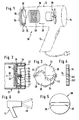
- a hairdryer 10 has a housing 12 and a handle 15 formed thereon.
- the housing 12 has an air inlet opening 14, an air duct 18 and an air outlet 16.
- a blower 20 and a heater 46 for generating an air flow 26 or a warm air flow.
- a rotor element 22 is provided in the air duct 18 between the air inlet opening 14 and the air outlet opening 16.
- a diaphragm 30 is assigned to the rotor element 22. Both components, the rotor element 22 and the diaphragm 30 are adapted to the circular cross section of the air duct 18 and formed as disks which are arranged transversely in the air duct 18. Both components essentially cover the air duct 18.
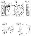
- the rotor element 22 has openings 24. These openings are either distributed uniformly over a circular ring of the rotor element 22 (FIG. 8) or are provided in individual sectors 40 (FIG. 3) which are arranged adjacent to unbroken sectors 38.
- the rotor element 22 has a plurality of air guide elements, in particular blades 28, distributed over the circumference.
- the diaphragm 30, which is arranged directly adjacent to the rotor element 22, has passage openings 32, which are preferably designed as an elongated, central slot 36 or as a sector-like section.
- the openings 24 in the rotor element 22 can have a cylindrical shape or a conical shape 242, wherein a tube axis 34 of the opening 241 can also be inclined to the air flow 26.
- the rotor element 22 is rotatably mounted on a support 60 provided in the air guide duct 18 and consisting of several arms 56 via a bearing 52 by means of an axis 54.
- the aperture 30 and the rotor element 22 are arranged essentially concentrically in FIG.
- the housing 12 or the air duct 18 have means for generating a secondary air flow 42, the strength of which can be varied by means of a schematically indicated control 44.
- the rotor element 22 is acted upon either radially or axially by the secondary air flow 42. It is also possible to apply a secondary air flow 42 to the rotor element 22 in addition to the main air flow 26 or exclusively to a secondary air flow 42 for driving the rotor element 22. It is also within the scope of the invention to design the secondary air flow as a means for braking the rotor element 22 driven by the main air flow.
- the blower 20 is put into operation and generates an air flow which partially or completely acts on the correspondingly inclined blades 28 of the rotor element 22 and generates a torque which sets the rotor element 22 in rotation.
- the speed of rotation of the rotor element 22 can be varied by the controller 44 or by other measures.
- the various openings 24 of the rotor element 22 come into congruence with the passage opening 32 of the diaphragm 30 at different times and at this time open the diaphragm / rotor element combination for the main air flow 26.
- Aperture 30 can achieve different temporal and / or spatial variations in the air flow exiting the hair dryer 10.
- an airflow vibration 50 is generated.
- the two air streams swing towards and away from each other in a fan shape. Due to the uniform distribution of the openings 24 (FIG. 8), there is essentially only a slight pulsing of the air flow, since for each angle of rotation of the rotor element 22 with respect to the aperture 32, an aperture 24 or a part thereof coincides with the slot 36 of the aperture 30.
- openings 24 and the passage openings 32 are within the scope of the invention.
- the speed of the rotor element can be set to values that take into account the individual needs of the user. In practice, speeds in the range from 1 to 50 Hz, in particular 10 to 20 Hz, have proven to be advantageous.
Landscapes
- Cleaning And Drying Hair (AREA)
- Cosmetics (AREA)
- Drying Of Solid Materials (AREA)
Claims (10)
- Sèche-cheveux (10) comportant un boîtier (12) qui présente un orifice d'entrée d'air (14), un canal de guidage d'air (18) et un orifice de sortie d'air (16), dans lequel est agencé dans le canal de guidage d'air (18) un ventilateur (20) pour la production d'un écoulement d'air (26) et un élément de rotor (22) qui est monté de manière à pouvoir tourner, qui présente au moins un passage (24) et qui comporte des moyens par lesquels l'élément de rotor (22) peut être mis en rotation lors d'une sollicitation par l'écoulement d'air (26), caractérisé en qu'un obturateur (30) fixe est adjoint à l'élément de rotor (22), l'obturateur (30) fermant au moins partiellement le canal de guidage d'air (18) et présentant des orifices de passage (32) de façon que, pendant le fonctionnement du sèche-cheveux (10), des passages (24) de l'élément de rotor (22) mis en rotation et des orifices de passage (32) de l'obturateur (30) soient temporairement en coïncidence l'un avec l'autre.
- Sèche-cheveux suivant la revendication 1, caractérisé en ce que l'élément de rotor (22) est réalisé sous la forme d'un disque et présente des passages (24) qui sont agencés par paires de façon opposée sur l'élément de rotor (22).
- Sèche-cheveux suivant la revendication 1 ou 2, caractérisé en ce que les passages (24) sont réalisés en forme de tuyau et en ce que l'axe de tuyau (34) présente de préférence une inclinaison par rapport à l'axe de rotation de l'élément de rotor (22).
- Sèche-cheveux suivant l'une au moins des revendications précédentes, caractérisé en ce que les passages (24) sont agencés de façon régulièrement répartie sensiblement sur le pourtour sur une couronne de l'élément de rotor (22) et en ce que l'obturateur (30) présente de préférence un orifice de passage (32) avec une forme d'orifice de façon que dans chaque position angulaire de l'élément de rotor (22) par rapport à l'obturateur (30) des passages (24) et des orifices de passage (32) viennent au moins partiellement en coïncidence l'un avec l'autre.
- Sèche-cheveux suivant au moins l'une des revendications 1 à 3, caractérisé en ce que l'élément de rotor (22) présente des secteurs avec des passages (40) et des secteurs sans passages (38) qui sont agencés de préférence au voisinage l'un de l'autre et en ce que l'obturateur présente de préférence un orifice de passage (32) avec une forme d'orifice de façon que sur une zone d'angle de rotation déterminée les passages (24) et les orifices de passage (32) ne viennent pas en coïncidence l'un avec l'autre.
- Sèche-cheveux suivant l'une au moins des revendications précédentes, caractérisé en ce que des passages (24) voisins suivant le pourtour présentent une distance radiale différente par rapport à l'axe de rotation sur l'élément de rotor (22) et en ce que les orifices de passage (32) sont réalisés de préférence sous la forme d'une fente (36) centrée allongée ou d'un tronçon en genre de secteur.
- Sèche-cheveux suivant l'une au moins des revendications précédentes, caractérisé en ce que les moyens sur l'élément de rotor (22) sont réalisés sous la forme d'éléments de guidage d'air, en particulier d'ailettes (28), qui sont répartis sur le pourtour et par lesquels l'écoulement d'air (26, 42) peut être dévié pour la production d'un couple de rotation.
- Sèche-cheveux suivant l'une au moins des revendications précédentes, caractérisé en ce que les moyens sur l'élément de rotor (22) sont sollicités par un écoulement d'air secondaire (42).
- Sèche-cheveux suivant la revendication 8, caractérisé en ce que la force de l'écoulement d'air secondaire (42) peut être modifiée au moyen d'une commande (44) par l'intermédiaire par exemple d'un ajutage réglable.
- Sèche-cheveux suivant l'une au moins des revendications précédentes, caractérisé en ce que des moyens sont prévus pour le freinage de l'élément de rotor (22).
Applications Claiming Priority (2)
| Application Number | Priority Date | Filing Date | Title |
|---|---|---|---|
| DE9016029U DE9016029U1 (de) | 1990-11-24 | 1990-11-24 | Föhndüse |
| DE9016029U | 1990-11-24 |
Publications (3)
| Publication Number | Publication Date |
|---|---|
| EP0487933A2 EP0487933A2 (fr) | 1992-06-03 |
| EP0487933A3 EP0487933A3 (en) | 1993-02-03 |
| EP0487933B1 true EP0487933B1 (fr) | 1995-03-01 |
Family
ID=6859669
Family Applications (2)
| Application Number | Title | Priority Date | Filing Date |
|---|---|---|---|
| EP91118695A Expired - Lifetime EP0487932B1 (fr) | 1990-11-24 | 1991-11-02 | Buse pour appareil de séchage de cheveux |
| EP91118696A Expired - Lifetime EP0487933B1 (fr) | 1990-11-24 | 1991-11-02 | Sèche-cheveux |
Family Applications Before (1)
| Application Number | Title | Priority Date | Filing Date |
|---|---|---|---|
| EP91118695A Expired - Lifetime EP0487932B1 (fr) | 1990-11-24 | 1991-11-02 | Buse pour appareil de séchage de cheveux |
Country Status (5)
| Country | Link |
|---|---|
| EP (2) | EP0487932B1 (fr) |
| AT (2) | ATE118997T1 (fr) |
| DE (3) | DE9016029U1 (fr) |
| ES (1) | ES2075303T3 (fr) |
| HK (2) | HK92896A (fr) |
Families Citing this family (9)
| Publication number | Priority date | Publication date | Assignee | Title |
|---|---|---|---|---|
| DE9016029U1 (de) * | 1990-11-24 | 1991-03-14 | Fedtke, Stephen, 2000 Hamburg | Föhndüse |
| DE4236036C2 (de) * | 1992-10-24 | 1998-11-26 | Braun Ag | Luftdurchströmbares Gerät zur Haartrocknung oder Haarformung |
| DE4321573C2 (de) * | 1993-06-29 | 2000-02-03 | Braun Gmbh | Luftleitvorrichtung für einen Haartrockner |
| GB2281035A (en) * | 1993-08-18 | 1995-02-22 | John Mcarthur | Hair dryer deflector nozzle |
| DE4344109A1 (de) * | 1993-12-23 | 1995-06-29 | Braun Ag | Verstellbarer Pulsator |
| US5473824A (en) * | 1994-03-21 | 1995-12-12 | Conair Corporation | Rotating outlet for hair dryers |
| GB2374801B (en) * | 2001-04-27 | 2003-03-26 | Richards Morphy N I Ltd | Improvements to hairdryers |
| CN100391381C (zh) * | 2005-04-21 | 2008-06-04 | 王昌满 | 密封式吹风机外壳体 |
| US8082679B1 (en) * | 2009-06-22 | 2011-12-27 | Carol Arnim | Magnetically directed hair dryer nozzle |
Family Cites Families (7)
| Publication number | Priority date | Publication date | Assignee | Title |
|---|---|---|---|---|
| US4132360A (en) * | 1977-08-22 | 1979-01-02 | General Electric Company | Pulsating hair dryer |
| US4295283A (en) * | 1979-05-21 | 1981-10-20 | Conair Corporation | Air diffuser for a hair dryer |
| CA1183345A (fr) * | 1981-07-13 | 1985-03-05 | Sunbeam Corporation | Seche-cheveux a air pulse |
| JPH0614648Y2 (ja) * | 1989-04-07 | 1994-04-20 | 株式会社吉原 | 温風パルス発生器 |
| CH680978A5 (en) * | 1990-02-09 | 1992-12-31 | Spemot Ag | Pulsator for airflow in hair-drier - has rotor disc with vanes and fixed disc both with segments cut=out, and uses centrifugal brakes to control rotor speed |
| DE9016029U1 (de) * | 1990-11-24 | 1991-03-14 | Fedtke, Stephen, 2000 Hamburg | Föhndüse |
| CH682291A5 (fr) * | 1991-02-13 | 1993-08-31 | Spemot Ag |
-
1990
- 1990-11-24 DE DE9016029U patent/DE9016029U1/de not_active Expired - Lifetime
-
1991
- 1991-11-02 AT AT91118696T patent/ATE118997T1/de active
- 1991-11-02 EP EP91118695A patent/EP0487932B1/fr not_active Expired - Lifetime
- 1991-11-02 DE DE59105979T patent/DE59105979D1/de not_active Expired - Fee Related
- 1991-11-02 ES ES91118695T patent/ES2075303T3/es not_active Expired - Lifetime
- 1991-11-02 AT AT91118695T patent/ATE124851T1/de not_active IP Right Cessation
- 1991-11-02 DE DE59104778T patent/DE59104778D1/de not_active Expired - Fee Related
- 1991-11-02 EP EP91118696A patent/EP0487933B1/fr not_active Expired - Lifetime
-
1996
- 1996-05-30 HK HK92896A patent/HK92896A/xx not_active IP Right Cessation
- 1996-05-30 HK HK92996A patent/HK92996A/xx not_active IP Right Cessation
Also Published As
| Publication number | Publication date |
|---|---|
| EP0487932B1 (fr) | 1995-07-12 |
| DE9016029U1 (de) | 1991-03-14 |
| DE59104778D1 (de) | 1995-04-06 |
| ES2075303T3 (es) | 1995-10-01 |
| HK92996A (en) | 1996-06-07 |
| EP0487933A2 (fr) | 1992-06-03 |
| DE59105979D1 (de) | 1995-08-17 |
| EP0487932A3 (en) | 1993-02-03 |
| ATE124851T1 (de) | 1995-07-15 |
| ATE118997T1 (de) | 1995-03-15 |
| HK92896A (en) | 1996-06-07 |
| EP0487932A2 (fr) | 1992-06-03 |
| EP0487933A3 (en) | 1993-02-03 |
Similar Documents
| Publication | Publication Date | Title |
|---|---|---|
| EP0439781B1 (fr) | Séchoir à cheveux | |
| DE2837543C2 (de) | Dunstabzugsvorrichtung | |
| DE4321573C2 (de) | Luftleitvorrichtung für einen Haartrockner | |
| EP0487933A2 (fr) | Sèche-cheveux | |
| DE1561654A1 (de) | Vorrichtung zum Sieben eines in Fluessigkeit verteilten Gemisches von Feststoffen | |
| DE4429473C2 (de) | Windsichter | |
| DE19514723A1 (de) | Färbemaschine für textile Fasern | |
| EP0421182B1 (fr) | Mélangeur d'air | |
| DE4131748A1 (de) | Heiss-umluftgeraet zum garen von lebensmitteln | |
| DE3426206C2 (fr) | ||
| EP0735831A1 (fr) | Pulsateur reglable | |
| DE2731289A1 (de) | Gestaltung des schmutzgaseinlasses fuer einen zyklonabscheider | |
| WO1982003026A1 (fr) | Procede et dispositif de pulverisation d'un liquide ou d'une suspension | |
| DE2148051A1 (de) | Einrichtung fuer den waerme- und/oder stoffaustausch zwischen substanzen und gasen | |
| EP0465607B1 (fr) | Desintegrateur a percussion | |
| EP0503210A1 (fr) | Pulsateur à fréquence variable pour la disposition du domaine d'entrée de l'air dans un séchoir à cheveux | |
| CH682293A5 (en) | Pulsator for electric hair-dryer air channel - uses baffle lamella elements and rotor with rotation axis perpendicular to air flow direction | |
| DE19501309A1 (de) | Verwirbelung der Einzelfilamente multifiler Fäden | |
| DE2348314C3 (de) | Haartrocknungsgerät | |
| DE2559507A1 (de) | Luftdrosseleinrichtung fuer durchzugsbelueftete elektrische maschinen | |
| DE812408C (de) | Sirene zur Erzeugung gerichteter Schallwellen | |
| DE2408080A1 (de) | Verfahren und vorrichtung zum gleichmaessigen ablegen von synthesefasern | |
| EP0832996A1 (fr) | Méthode et dispositif de fabrication d'un fil ayant des zones épaisses et fines | |
| DE1500605A1 (de) | Vorrichtung zum Zerstaeuben von Fluessigkeiten an der Luft oder in einem Gas | |
| DE7047915U (de) | Trommelmaschine zum Behandeln von Textilien |
Legal Events
| Date | Code | Title | Description |
|---|---|---|---|
| PUAI | Public reference made under article 153(3) epc to a published international application that has entered the european phase |
Free format text: ORIGINAL CODE: 0009012 |
|
| AK | Designated contracting states |
Kind code of ref document: A2 Designated state(s): AT BE CH DE DK ES FR GB GR IT LI LU NL SE |
|
| PUAL | Search report despatched |
Free format text: ORIGINAL CODE: 0009013 |
|
| AK | Designated contracting states |
Kind code of ref document: A3 Designated state(s): AT BE CH DE DK ES FR GB GR IT LI LU NL SE |
|
| 17P | Request for examination filed |
Effective date: 19930114 |
|
| 17Q | First examination report despatched |
Effective date: 19940425 |
|
| GRAA | (expected) grant |
Free format text: ORIGINAL CODE: 0009210 |
|
| AK | Designated contracting states |
Kind code of ref document: B1 Designated state(s): AT BE CH DE DK ES FR GB GR IT LI LU NL SE |
|
| PG25 | Lapsed in a contracting state [announced via postgrant information from national office to epo] |
Ref country code: GR Free format text: LAPSE BECAUSE OF FAILURE TO SUBMIT A TRANSLATION OF THE DESCRIPTION OR TO PAY THE FEE WITHIN THE PRESCRIBED TIME-LIMIT Effective date: 19950301 Ref country code: IT Free format text: LAPSE BECAUSE OF FAILURE TO SUBMIT A TRANSLATION OF THE DESCRIPTION OR TO PAY THE FEE WITHIN THE PRE;WARNING: LAPSES OF ITALIAN PATENTS WITH EFFECTIVE DATE BEFORE 2007 MAY HAVE OCCURRED AT ANY TIME BEFORE 2007. THE CORRECT EFFECTIVE DATE MAY BE DIFFERENT FROM THE ONE RECORDED.SCRIBED TIME-LIMIT Effective date: 19950301 Ref country code: DK Effective date: 19950301 Ref country code: ES Free format text: THE PATENT HAS BEEN ANNULLED BY A DECISION OF A NATIONAL AUTHORITY Effective date: 19950301 |
|
| REF | Corresponds to: |
Ref document number: 118997 Country of ref document: AT Date of ref document: 19950315 Kind code of ref document: T |
|
| GBT | Gb: translation of ep patent filed (gb section 77(6)(a)/1977) |
Effective date: 19950227 |
|
| REF | Corresponds to: |
Ref document number: 59104778 Country of ref document: DE Date of ref document: 19950406 |
|
| PG25 | Lapsed in a contracting state [announced via postgrant information from national office to epo] |
Ref country code: SE Effective date: 19950601 |
|
| ET | Fr: translation filed | ||
| RAP2 | Party data changed (patent owner data changed or rights of a patent transferred) |
Owner name: BRAUN AKTIENGESELLSCHAFT |
|
| PGFP | Annual fee paid to national office [announced via postgrant information from national office to epo] |
Ref country code: AT Payment date: 19951114 Year of fee payment: 5 Ref country code: BE Payment date: 19951114 Year of fee payment: 5 |
|
| REG | Reference to a national code |
Ref country code: CH Ref legal event code: PFA Free format text: BRAUN AKTIENGESELLSCHAFT TRANSFER- BRAUN AKTIENGESELLSCHAFT |
|
| PGFP | Annual fee paid to national office [announced via postgrant information from national office to epo] |
Ref country code: NL Payment date: 19951123 Year of fee payment: 5 |
|
| PG25 | Lapsed in a contracting state [announced via postgrant information from national office to epo] |
Ref country code: LU Free format text: LAPSE BECAUSE OF NON-PAYMENT OF DUE FEES Effective date: 19951130 |
|
| NLT2 | Nl: modifications (of names), taken from the european patent patent bulletin |
Owner name: BRAUN AKTIENGESELLSCHAFT |
|
| PLBE | No opposition filed within time limit |
Free format text: ORIGINAL CODE: 0009261 |
|
| STAA | Information on the status of an ep patent application or granted ep patent |
Free format text: STATUS: NO OPPOSITION FILED WITHIN TIME LIMIT |
|
| 26N | No opposition filed | ||
| PG25 | Lapsed in a contracting state [announced via postgrant information from national office to epo] |
Ref country code: AT Effective date: 19961102 |
|
| PGFP | Annual fee paid to national office [announced via postgrant information from national office to epo] |
Ref country code: FR Payment date: 19961114 Year of fee payment: 6 |
|
| PG25 | Lapsed in a contracting state [announced via postgrant information from national office to epo] |
Ref country code: BE Effective date: 19961130 |
|
| PGFP | Annual fee paid to national office [announced via postgrant information from national office to epo] |
Ref country code: CH Payment date: 19961219 Year of fee payment: 6 |
|
| BERE | Be: lapsed |
Owner name: BRAUN A.G. Effective date: 19961130 |
|
| PG25 | Lapsed in a contracting state [announced via postgrant information from national office to epo] |
Ref country code: NL Effective date: 19970601 |
|
| NLV4 | Nl: lapsed or anulled due to non-payment of the annual fee |
Effective date: 19970601 |
|
| PGFP | Annual fee paid to national office [announced via postgrant information from national office to epo] |
Ref country code: DE Payment date: 19971015 Year of fee payment: 7 |
|
| PGFP | Annual fee paid to national office [announced via postgrant information from national office to epo] |
Ref country code: GB Payment date: 19971023 Year of fee payment: 7 |
|
| PG25 | Lapsed in a contracting state [announced via postgrant information from national office to epo] |
Ref country code: FR Free format text: THE PATENT HAS BEEN ANNULLED BY A DECISION OF A NATIONAL AUTHORITY Effective date: 19971130 Ref country code: CH Free format text: LAPSE BECAUSE OF NON-PAYMENT OF DUE FEES Effective date: 19971130 Ref country code: LI Free format text: LAPSE BECAUSE OF NON-PAYMENT OF DUE FEES Effective date: 19971130 |
|
| REG | Reference to a national code |
Ref country code: CH Ref legal event code: PL |
|
| REG | Reference to a national code |
Ref country code: FR Ref legal event code: ST |
|
| PG25 | Lapsed in a contracting state [announced via postgrant information from national office to epo] |
Ref country code: GB Free format text: LAPSE BECAUSE OF NON-PAYMENT OF DUE FEES Effective date: 19981102 |
|
| GBPC | Gb: european patent ceased through non-payment of renewal fee |
Effective date: 19981102 |
|
| PG25 | Lapsed in a contracting state [announced via postgrant information from national office to epo] |
Ref country code: DE Free format text: LAPSE BECAUSE OF NON-PAYMENT OF DUE FEES Effective date: 19990901 |