EP0487939A1 - Ouvre-boîtes - Google Patents
Ouvre-boîtes Download PDFInfo
- Publication number
- EP0487939A1 EP0487939A1 EP91118756A EP91118756A EP0487939A1 EP 0487939 A1 EP0487939 A1 EP 0487939A1 EP 91118756 A EP91118756 A EP 91118756A EP 91118756 A EP91118756 A EP 91118756A EP 0487939 A1 EP0487939 A1 EP 0487939A1
- Authority
- EP
- European Patent Office
- Prior art keywords
- motor
- drive shaft
- housing
- state
- drive
- Prior art date
- Legal status (The legal status is an assumption and is not a legal conclusion. Google has not performed a legal analysis and makes no representation as to the accuracy of the status listed.)
- Granted
Links
- 230000006835 compression Effects 0.000 claims abstract description 15
- 238000007906 compression Methods 0.000 claims abstract description 15
- 239000011324 bead Substances 0.000 claims description 18
- 238000004804 winding Methods 0.000 claims description 5
- 238000002788 crimping Methods 0.000 claims description 3
- 238000003780 insertion Methods 0.000 claims description 3
- 230000037431 insertion Effects 0.000 claims description 3
- 229910000831 Steel Inorganic materials 0.000 description 1
- 230000002457 bidirectional effect Effects 0.000 description 1
- 230000000994 depressogenic effect Effects 0.000 description 1
- 238000010586 diagram Methods 0.000 description 1
- 230000000750 progressive effect Effects 0.000 description 1
- 239000010959 steel Substances 0.000 description 1
Images
Classifications
-
- B—PERFORMING OPERATIONS; TRANSPORTING
- B67—OPENING, CLOSING OR CLEANING BOTTLES, JARS OR SIMILAR CONTAINERS; LIQUID HANDLING
- B67B—APPLYING CLOSURE MEMBERS TO BOTTLES JARS, OR SIMILAR CONTAINERS; OPENING CLOSED CONTAINERS
- B67B7/00—Hand- or power-operated devices for opening closed containers
- B67B7/40—Devices for engaging tags, strips, or tongues for opening by tearing, e.g. slotted keys for opening sardine tins
-
- B—PERFORMING OPERATIONS; TRANSPORTING
- B67—OPENING, CLOSING OR CLEANING BOTTLES, JARS OR SIMILAR CONTAINERS; LIQUID HANDLING
- B67B—APPLYING CLOSURE MEMBERS TO BOTTLES JARS, OR SIMILAR CONTAINERS; OPENING CLOSED CONTAINERS
- B67B7/00—Hand- or power-operated devices for opening closed containers
- B67B7/38—Power-operated cutting devices
Definitions
- the invention relates to can openers comprising, in a housing, an electric motor capable of driving in rotation, by means of at least one toothed wheel, a drive shaft of which one end projects transversely to the one of the walls of the housing and carries a caster comprising a drive zone intended to come into contact with the crimping flange of a box, as well as a cutting wheel which is mounted idly around an axis disposed transversely to the 'drive shaft and of which a cutting sector protrudes from said wall practically opposite said drive zone of the caster and is intended to come and cut said bead.
- the invention relates, more precisely, can openers in which said drive shaft is mounted both rotatable and axially movable in the housing by means, on the one hand, of a bi-directional driving mechanism comprising a spring compression threaded on the drive shaft and bearing both on a wall of the housing and on the toothed wheel, and, on the other hand, a device for reversing the direction of rotation of the shaft d drive comprising two electrical switches, a so-called start switch and a so-called stop switch, which are mounted in the motor supply circuit so as to swap the connection connections of said motor to reverse its direction of rotation, so that the motor can take, via a control button actuated by the user, two states, ie a "forward" state for which the wheel applies the bead of the box against the wheel , or a "reverse” state for which the wheel allows the insertion or removal of the box.
- a bi-directional driving mechanism comprising a spring compression threaded on the drive shaft and bearing both on a wall of the housing
- Such a can opener has been described for example in French patent applications No. 8,916,043 and No. 8,918,203 filed on 05 12 1989 and 07 12 1989 respectively by plaintiff. It includes a bi-directional driving mechanism, the compression spring of which has the function of causing the caster to translate so as either to introduce the bead of the box between the caster and the wheel before opening or to remove it after opening, or to maintain the bead against the wheel during opening.
- the can opener includes a reversing device constituted by an electric circuit which fulfills the function of reversing the direction of rotation of the motor and delaying the duration heard between the command by the user. shifting the engine into reverse, and stopping the engine. The time delay is ensured by an electric circuit connected to the motor supply circuit.
- the invention aims to simplify the reversing device.
- the compression spring has two parts, a cylindrical part with contiguous turns whose internal surfaces are mounted in friction on the drive shaft and a frustoconical part with non-contiguous turns whose free end is likely to come occupy two positions, either a rest position for which it is in abutment against a finger arranged on a wall of the housing, or a working position for which it presses the stop switch so as to cut off the power to the motor, the spring having a winding direction such that, when the motor occupies its "forward” state, the turns of the cylindrical part of the spring spin on the drive shaft so that the free end is brought into the rest position, while, when the motor occupies its "reverse” state, the turns of the cylindrical part are clamped on the drive shaft. so as to drive the free end of the frusto-conical part towards its working position.
- the compression spring fulfills two functions: a function of moving the wheel forwards and a timing function defined by the angular distance between the finger and the stop switch.
- the timing is performed by a mechanical device, the electrical circuit is therefore simplified, which reduces the cost of the device.
- the compression spring does not show any wear since the tightening is modulated according to the direction of rotation.
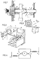
- FIG. 1 shows a schematic section of a can opener according to the invention
- FIG. 2 represents a partial perspective view illustrating the compression spring of which the free end is in the stop position on the stop switch
- Figure 3 is a schematic view of the compression spring in the stop position
- FIG. 4 represents the electrical diagram of the reversing device according to the invention.
- the can opener shown in Figure 1 comprises, in a housing 1, an electric motor (shown schematically at 2 in Figure 4) capable of driving in rotation, via at least one toothed wheel 3, a drive shaft 4, one end of which projects transversely from one of the walls 5, 6, 6 of the housing 1 and carries a roller 7 comprising a drive zone 8 intended to come into contact with the upper internal lateral region of the bead of crimping of the cover of a box (not shown), as well as a cutting wheel 9 which is mounted idly around an axis 10 disposed transversely to the drive shaft 4 and of which a cutting sector It projects from said wall 5 practically opposite said drive zone 8 of the caster 7 and is intended to cut the external lateral region of said bead.
- an electric motor shown schematically at 2 in Figure 4
- a drive shaft 4 capable of driving in rotation, via at least one toothed wheel 3
- a drive shaft 4 one end of which projects transversely from one of the walls 5, 6, 6 of the housing 1 and carries a roller
- the drive shaft 4 is mounted both rotatably and axially movable in the housing 1 by means of a bidirectional drive mechanism which comprises a lug 12, integral with the drive shaft 4 and capable of moving along an inclined lumen 13 (shown in dashed lines) formed on the toothed wheel 3, as well as a compression coil spring 14 preferably made of steel threaded on the drive shaft 4 and supported by its ends, d on the one hand, on a wall 6 of the housing 1 and, on the other hand, on the toothed wheel 3.
- a bidirectional drive mechanism which comprises a lug 12, integral with the drive shaft 4 and capable of moving along an inclined lumen 13 (shown in dashed lines) formed on the toothed wheel 3, as well as a compression coil spring 14 preferably made of steel threaded on the drive shaft 4 and supported by its ends, d on the one hand, on a wall 6 of the housing 1 and, on the other hand, on the toothed wheel 3.
- the lug 12 can drive the shaft 4 in rotation and in translation so that the drive shaft 4 can occupy, in the direction of rotation of said wheel 3, is an inactive position ( Figure 1) for which the caster 7 is moved away from the wheel 9 so as to allow the engagement or disengagement of the bead from the box, ie an active position (not shown) for which the caster 7 is brought closer to the wheel 9 so as to come into engagement with the bead and allow the cutting of the external lateral region of said bead.
- Figure 1 for which the caster 7 is moved away from the wheel 9 so as to allow the engagement or disengagement of the bead from the box
- an active position not shown
- the compression spring 14 is chosen so as to exert an axial compression force large enough to oppose the rise of the lug 12 along the lumen 13 when the caster 7 rotates in a vacuum, thus maintaining the shaft drive 4 in its inactive position (Figure 1), and low enough to allow the lug 12 to rise along the lumen 13, when the drive area 8 of the roller 7 is in contact with the bead of a box, thus maintaining the drive shaft 4 in its active position.
- the can opener further comprises a device for reversing the direction of rotation of the drive shaft 4 comprising two electrical switches 16, 17, a so-called switch 16 and a so-called stop switch 17, which are mounted in the motor supply circuit so as to swap the connection connections of said motor 2 to reverse its direction of rotation, so that the motor 2 can take , via a control button 18 actuated by the user, two states, either a "forward" state for which the roller 7 applies the bead of the box against the wheel 9, or a "reverse” state "for which the roller 7 allows the insertion or removal of the box.
- a device for reversing the direction of rotation of the drive shaft 4 comprising two electrical switches 16, 17, a so-called switch 16 and a so-called stop switch 17, which are mounted in the motor supply circuit so as to swap the connection connections of said motor 2 to reverse its direction of rotation, so that the motor 2 can take , via a control button 18 actuated by the user, two states, either a "forward" state for which the roller 7 applies the bead
- the electric motor 2 shown diagrammatically in FIG. 4, is a collector series motor which is connected to terminals A and B of an AC voltage sector and whose armature windings can, for example, be swapped in a manner known per se, so as to allow the motor to rotate in both meaning.
- the compression spring 14 has two parts, a cylindrical part 19 with contiguous turns whose internal surfaces 20 are frictionally mounted on the drive shaft 4 and a frustoconical part 21 with non-contiguous turns free 22 is capable of coming to occupy two positions, either a rest position (shown in broken lines in Figures 2 and 3) for which it is in abutment against a finger 23 arranged on the wall 6 of the housing 1, or a position of work (shown in solid lines in FIGS.
- the spring 14 having a winding direction such that, when the motor 2 occupies its "forward” state, the turns of the cylindrical part 19 of the spring 14 slip on the drive shaft 4 so that the free end 22 is brought into the rest position, while, lo rsque the motor 2 occupies its "reverse” state, the turns of the cylindrical part 19 are clamped on the drive shaft 4 so as to drive the free end 22 of the frusto-conical part 21 towards its working position.
- the control button 18 can occupy two positions, a depressed position (shown in dashed lines in FIG.
- Each switch 16, 17 can each occupy two states, a state called “low” (shown in solid lines in Figure 4) and a state called “high” (shown in broken lines in Figure 4).
- the run switch 16 has been chosen to so that its "high” state corresponds to a non-actuation of its key while the stop switch 17 has been chosen so that its "high” state corresponds to the actuation of its key.
- control button 18 In an initial step, the control button 18 is in the released position (solid lines in Figure 2), the on and off switches 16 are in their "high” state (broken lines in Figure 4); engine 2 is stopped. The spring is tightened on the drive shaft 4.
- a "forward” step the user inserts the bead of the box between the wheel 9 and the roller 7 and then starts the device.
- the button 18 then presses the key of the on switch 16, which changes to its "low” state (solid lines in FIG. 4) and keeps the stop switch 17 in its “high” state.
- the lug 12 rises along the light 13 against the axial force exerted by the spring of compression 14, which brings the shaft 4 into translation in the active position, the lug 12 then drives the shaft 4 in rotation, thus allowing the cutting of the bead.
- the spring clamped on the shaft by its cylindrical part 19 will be rotated by the shaft until the free end 22 abuts against the finger 23. At this stage, by friction, the movement will tend to open the turns of the spring, it will not oppose significant force to the rotation of the shaft.
- the spring is driven by the shaft 4 due to the direction of winding chosen so that the cylindrical part 19 of the spring is tightened all the more strongly that one opposes the movement.
- the free end of the frustoconical part is therefore rotated until it comes into contact with the button of the stop switch 17, which changes state and then occupies its "low” state.
- the engine power is cut, we find our at the initial stage.
- an angular distance between the finger 23 and the button of the stop switch 17 is chosen of approximately 45 °; the time elapsing between the reversal of the direction of rotation of the motor 2 and the interruption of the supply is approximately one second.
Landscapes
- Engineering & Computer Science (AREA)
- Mechanical Engineering (AREA)
- Lock And Its Accessories (AREA)
- Devices For Opening Bottles Or Cans (AREA)
- Glass Compositions (AREA)
- Control And Other Processes For Unpacking Of Materials (AREA)
- Catching Or Destruction (AREA)
- Table Devices Or Equipment (AREA)
Abstract
Description
- L'invention se rapporte aux ouvre-boîtes comprenant, dans un boîtier, un moteur électrique susceptible d'entraîner en rotation, par l'intermédiaire d'au moins une roue dentée, un arbre d'entraînement dont une extrémité fait saillie transversalement à l'une des parois du boîtier et porte une roulette comportant une zone d'entraînement destinée à venir en contact avec le bourrelet de sertissage d'une boîte, ainsi qu'une molette coupante qui est montée folle autour d'un axe disposé transversalement à l'arbre d'entraînement et dont un secteur tranchant fait saillie de ladite paroi pratiquement en regard de ladite zone d'entraînement de la roulette et est destiné à venir découper ledit bourrelet.
- L'invention concerne, plus précisement, les ouvre-boîtes dans lesquels ledit arbre d'entraînement est monté à la fois rotatif et mobile axialement dans le boîtier au moyen, d'une part, d'un mécanisme entraîneur bi-directionnel comportant un ressort de compression enfilé sur l'arbre d'entraînement et prenant appui à la fois sur une paroi du boîtier et sur la roue dentée, et, d'autre part, d'un dispositif d'inversion du sens de rotation de l'arbre d'entraînement comportant deux commutateurs électriques, un commutateur dit de marche et un commutateur dit d'arrêt, qui sont montés dans le circuit d'alimentation du moteur de manière à permuter les connexions de branchement dudit moteur pour inverser son sens de rotation, de telle sorte que le moteur puisse prendre, par l'intermédiaire d'un bouton de commande actionné par l'usager, deux états, soit un état "marche avant" pour lequel la roulette applique le bourrelet de la boîte contre la molette, soit un état "marche arrière" pour lequel la roulette permet l'insertion ou l'enlèvement de la boîte.
- Un tel ouvre-boîtes a été décrit par exemple dans les demandes de brevet français N° 8 916 043 et N° 8 918 203 déposées respectivement le 05 12 1989 et le 07 12 1989 par la
demanderesse. Il comporte un mécanisme entraîneur bi-directionnel dont le ressort de compression a pour fonction de provoquer une translation de la roulette de façon, soit à introduire le bourrelet de la boîte entre la roulette et la molette avant ouverture ou à le retirer après ouverture, soit à maintenir le bourrelet contre la molette pendant l'ouverture.
D'autre part, l'ouvre-boîtes comporte un dispositif d'inversion constitué par un circuit électrique qui remplit la fonction d'inversion du sens de rotation du moteur et de temporisation de la durée s'écoutant entre la commande par l'usager faisant passer le moteur en marche arrière, et l'arrêt du moteur. La temporisation est assurée par un circuit électrique branché sur le circuit d'alimentation du moteur. - L'invention a pour but de simplifier le dispositif d'inversion.
- Selon l'invention, le ressort de compression comporte deux parties, une partie cylindrique à spires jointives dont les surfaces internes sont montées en friction sur l'arbre d'entraînement et une partie tronconique à spires non jointives dont une extrémité libre est susceptible de venir occuper deux positions, soit une position de repos pour laquelle elle est en butée contre un doigt agencé sur une paroi du boîtier, soit une position de travail pour laquelle elle appuie sur le commutateur d'arrêt de manière à couper l'alimentation du moteur, le ressort ayant un sens d'enroulement tel que, lorsque le moteur occupe son état "marche avant", les spires de la partie cylindrique du ressort patinent sur l'arbre d'entraînement de manière que l'extrémité libre soit amenée en position de repos, tandis que, lorsque le moteur occupe son état "marche arrière", les spires de la partie cylindrique sont serrées sur l'arbre d'entraînement de manière à entraîner l'extrémité libre de la partie tronconique vers sa position de travail.
- Grâce à ce dispositif, on comprendra que, dès que l'usager appuie sur le bouton de commande pour faire passer le moteur dans son état "marche arrière", l'arbre d'entraînement est entraîné automatiquement en sens inverse, provoquant ainsi le serrage progressif des spires autour de l'arbre et au bout d'un certain temps le contact entre l'extrémité libre du ressort et le commutateur d'arrêt qui coupe l'alimentation du moteur.
Ainsi, le ressort de compression remplit deux fonctions : une fonction de déplacement vers l'avant de la molette et une fonction de temporisation définie par la distance angulaire entre le doigt et le commutateur d'arrêt. La temporisation étant réalisée par un dispositif mécanique, le circuit électrique est donc simplifié, ce qui diminue le coût de l'appareil. De plus, grâce à sa forme particulière, le ressort de compression n'accuse pas d'usure puisque le serrage est modulé selon le sens de rotation. - Les caractéristiques et avantages de l'invention ressortiront d'ailleurs de la description qui va suivre, à titre d'exemple, en référence au dessin annexé dans lequel :
la figure 1 représente une coupe schématique d'un ouvre-boîtes selon l'invention ; la figure 2 représente une vue en perspective partielle illustrant le ressort de compression dont l'extrémité libre est en position d'arrêt sur le commutateur d'arrêt ; la figure 3 est une vue schématique du ressort de compression en positon d'arrêt ; la figure 4 représente le schéma électrique du dispositif d'inversion selon l'invention. - L'ouvre-boîtes représenté sur la Figure 1 comprend, dans un boîtier 1, un moteur électrique (schématisé en 2 sur la Figure 4) susceptible d'entraîner en rotation, par l'intermédiaire d'au moins une roue dentée 3, un arbre d'entraînement 4 dont une extrémité fait saillie transversalement à l'une 5 des parois 5,6 du boîtier 1 et porte une roulette 7 comportant une zone d'entraînement 8 destinée à venir en contact avec la région supérieure latérale interne du bourrelet de sertissage du couvercle d'une boîte (non représentée), ainsi qu'une molette coupante 9 qui est montée folle autour d'un axe 10 disposé transversalement à l'arbre d'entraînement 4 et dont un secteur tranchant Il fait saillie de ladite paroi 5 pratiquement en regard de ladite zone d'entraînement 8 de la roulette 7 et est destiné à venir découper la région latérale externe dudit bourrelet.
- L'arbre d'entraînement 4 est monté à la fois rotatif et mobile axialement dans le boîtier 1 au moyen d'un mécanisme entraîneur bidirectionnel qui comporte un ergot 12, solidaire de l'arbre d'entraînement 4 et susceptible de se déplacer le long d'une lumière inclinée 13 (représentée en traits interrompus) pratiquée sur la roue dentée 3, ainsi qu'un ressort de compression à boudin 14 de préférence en acier enfilé sur l'arbre d'entraînement 4 et prenant appui par ses extrémités, d'une part, sur une paroi 6 du boîtier 1 et, d'autre part, sur la roue dentée 3.
- Entre la roue dentée 3 et la paroi 5 du boîtier 1 sont interposées de manière connue en soi des rondelles 15, du type Belleville.
- L'ergot 12 peut entraîner l'arbre 4 en rotation et en translation de manière que l'arbre d'entraînement 4 puisse occuper, suivant le sens de rotation de ladite roue 3, soit une position inactive (Figure 1) pour laquelle la roulette 7 est éloignée de la molette 9 de manière à permettre l'engagement ou le désengagement du bourrelet de la boîte, soit une position active (non représentée) pour laquelle la roulette 7 est rapprochée de la molette 9 de manière à venir en prise avec le bourrelet et permettre le découpage de la région latérale externe dudit bourrelet.
Le ressort de compression 14 est choisi de manière à exercer une force de compression axiale suffisamment importante pour s'opposer à la montée de l'ergot 12 le long de la lumière 13 lorsque la roulette 7 tourne dans le vide, maintenant ainsi l'arbre d'entraînement 4 dans sa position inactive (Figure 1), et suffisamment faible pour autoriser l'ergot 12 à monter le long de la lumière 13, lorsque la zone d'entraînement 8 de la roulette 7 est en contact avec le bourrelet d'une boîte, maintenant ainsi l'arbre d'entraînement 4 dans sa position active. - Comme on le voit mieux sur les Figures 2, 3 et 4, l'ouvre-boîtes comporte en outre un dispositif d'inversion du sens de rotation de l'arbre d'entraînement 4 comportant deux commutateurs électriques 16, 17, un commutateur dit de marche 16 et un commutateur dit d'arrêt 17, qui sont montés dans le circuit d'alimentation du moteur de manière à permuter les connexions de branchement dudit moteur 2 pour inverser son sens de rotation, de telle sorte que le moteur 2 puisse prendre, par l'intermédiaire d'un bouton de commande 18 actionné par l'usager, deux états, soit un état "marche avant" pour lequel la roulette 7 applique le bourrelet de la boîte contre la molette 9, soit un état "marche arrière" pour lequel la roulette 7 permet l'insertion ou l'enlèvement de la boîte.
- Le moteur électrique 2, schématisé sur la Figure 4 est un moteur série à collecteur qui est branché aux bornes A et B d'un secteur à tension alternative et dont, par exemple, les enroulements d'induit peuvent être permutés de façon connue en soi, de manière à autoriser la rotation du moteur dans les deux sens.
- Selon l'invention, le ressort de compression 14 comporte deux parties, une partie cylindrique 19 à spires jointives dont les surfaces internes 20 sont montées en friction sur l'arbre d'entraînement 4 et une partie tronconique 21 à spires non jointives dont une extrémité libre 22 est susceptible de venir occuper deux positions, soit une position de repos (représentée en traits interrrompus sur les Figures 2 et 3) pour laquelle elle est en butée contre un doigt 23 agencé sur la paroi 6 du boîtier 1, soit une position de travail (représentée en traits pleins sur les Figures 2 et 3) pour laquelle elle appuie sur la touche du commutateur d'arrêt 17 de manière à couper l'alimentation du moteur 2, le ressort 14 ayant un sens d'enroulement tel que, lorsque le moteur 2 occupe son état "marche avant", les spires de la partie cylindrique 19 du ressort 14 patinent sur l'arbre d'entraînement 4 de manière que l'extrémité libre 22 soit amenée en position de repos, tandis que, lorsque le moteur 2 occupe son état "marche arrière", les spires de la partie cylindrique 19 sont serrées sur l'arbre d'entraînement 4 de manière à entraîner l'extrémité libre 22 de la partie tronconique 21 vers sa position de travail.
Le bouton de commande 18 peut occuper deux positions, une position enfoncée (représentée en traits interrompus sur la Figure 2) pour laquelle l'usager maintient appuyé ledit bouton à l'encontre de moyens élastiques (non représentés) et une position relâchée (représentée en traits pleins sur la Figure 2) en laquelle il est maintenu par les moyens élastiques quand l'usager le relâche.
Chaque commutateur 16, 17 peut occuper chacun deux états, un état dit "bas" (représenté en traits pleins sur la Figure 4) et un état dit "haut" (représenté en traits interrompus sur la Figure 4). Le commutateur de marche 16 a été choisi de manière que son état "haut" corresponde à un non actionnement de sa touche alors que le commutateur d'arrêt 17 a été choisi de manière que son état "haut" corresponde à l'actionnement de sa touche. - Dans un but de clarté on va préciser le fonctionnement du mécanisme décrit ci-dessus, que l'on peut décomposer en trois étapes.
- Dans une étape initiale, le bouton de commande 18 est en position relachée (traits pleins Figure 2), les commutateurs de marche 16 et d'arrêt 17 sont dans leur état "haut" (traits interrompus Figure 4) ; le moteur 2 est arrêté. Le ressort est serré sur l'arbre d'entraînement 4.
- Dans une étape "marche avant", l'utilisateur insère le bourrelet de la boîte entre la molette 9 et la roulette 7 puis il met en marche l'appareil. Pour celà, l'utilisateur appuie sur le bouton de commande 18 qui passe à son état enfoncé (traits interrompus Figure 2). Le bouton 18 appuie alors sur la touche du commutateur de marche 16, qui passe à son état "bas" (traits pleins Figure 4) et maintient le commutateur d'arrêt 17 dans son état "haut". Le moteur 2 étant alimenté, il passe dans son état "marche avant". Le moteur entraîne alors la roue dentée 3 en rotation. Grâce à la friction exercée par le bourrelet sur la roulette 7 et la force exercée par la lumière 13 sur l'ergot 12, l'ergot 12 monte le long de la lumière 13 à l'encontre de la force axiale exercée par le ressort de compression 14, ce qui amène par translation l'arbre 4 en position active, l'ergot 12 entraîne ensuite l'arbre 4 en rotation permettant ainsi le découpage du bourrelet. Simultanément, le ressort serré sur l'arbre par sa partie cylindrique 19 va être entraîné en rotation par l'arbre jusqu'à ce que l'extrémité libre 22 vienne en butée contre le doigt 23. A ce stade, par friction, le mouvement va tendre à ouvrir les spires du ressort, celui-ci n'opposera pas d'effort important à la rotation de l'arbre.
- Dans une étape "marche arrière", quand le découpage est terminé, l'utilisateur relâche sa pression sur le bouton de commande 18 qui passe dans sa position relâchée (traits pleins, Figure 2), les deux commutateurs de marche 16 et d'arrêt 17 changent d'état : le commutateur de marche 16 est dans son état "haut" (traits interrompus Figure 4) et le commutateur d'arrêt 17 est dans son état "bas" (traits pleins Figure 4). L'alimentation du moteur est inversée, le moteur occupe son état "marche arrière". La roue 3 tournant dans l'autre sens, l'ergot 12 descend le long de la lumière 13 de manière que la roulette 7 soit éloignée de la molette 9 par translation, libérant ainsi le bourrelet, ce qui permet à l'utilisateur d'ôter la boîte. Simultanément, le ressort se trouve entraîné par l'arbre 4 du fait du sens d'enroulement choisi de manière que la partie cylindrique 19 du ressort soit serrée d'autant plus fort que l'on s'oppose au mouvement. L'extrémité libre de la partie tronconique est donc entraînée en rotation jusqu'à venir en contact avec la touche du commutateur d'arrêt 17, qui change d'état et occupe alors son état "bas". L'alimentation du moteur est coupée, on se retrouve à l'étape initiale.
- Dans un mode de réalisation préférée, on choisit une distance angulaire entre le doigt 23 et la touche du commutateur d'arrêt 17 d'environ 45° ; le temps s'écoulant entre l'inversion du sens de rotation du moteur 2 et la coupure de l'alimentation est d'environ une seconde.
Claims (1)
- Ouvre-boîtes comprenant, dans un boîtier (1), un moteur électrique (2) susceptible d'entraîner en rotation, par l'intermédiaire d'au moins une roue dentée (3), un arbre d'entraînement (4) dont une extrémité fait saillie transversalement à l'une (5) des parois (5, 6) du boîtier (1) et porte une roulette (7) comportant une zone d'entraînement (8) destinée à venir en contact avec le bourrelet de sertissage d'une boîte, ainsi qu'une molette coupante (9) qui est montée folle autour d'un axe (10) disposé transversalement à l'arbre d'entraînement (4) et dont un secteur tranchant (11) fait saillie de ladite paroi (5) pratiquement en regard de ladite zone d'entraînement (8) de la roulette (7) et est destiné à venir découper ledit bourrelet, ledit arbre d'entraînement (4) étant monté à la fois rotatif et mobile axialement dans le boîtier (1) au moyen, d'une part, d'un mécanisme entraîneur bi-directionnel comportant un ressort de compression (14) enfilé sur l'arbre d'entraînement (4) et prenant appui à la fois sur une paroi (6) du boîtier (1) et sur la roue dentée (3), et, d'autre part, d'un dispositif d'inversion du sens de rotation de l'arbre d'entraînement (4) comportant deux commutateurs électriques (16, 17), un commutateur dit de marche (16) et un commutateur dit d'arrêt (17), qui sont montés dans le circuit d'alimentation du moteur (2) de manière à permuter les connexions de branchement dudit moteur (2) pour inverser son sens de rotation, de telle sorte que le moteur (2) puisse prendre, par l'intermédiaire d'un bouton de commande (18) actionné par l'usager, deux états, soit un état "marche avant" pour lequel la roulette (7) applique le bourrelet de la boîte contre la molette (9), soit un état "marche arrière" pour lequel la roulette (7) permet l'insertion ou l'enlèvement de la boîte,
caractérisé en ce que le ressort de compression (14) comporte deux parties (19, 20) une partie cylindrique (19) à spires jointives dont les surfaces internes (20) sont montées en friction sur l'arbre d'entraînement (4) et une partie tronconique (21) à spires non jointives dont une extrémité libre (22) est susceptible de venir occuper deux positions, soit une position de repos pour laquelle elle est en butée contre un doigt (23) agencé sur la paroi (6) du boîtier (1), soit une position de travail pour laquelle elle appuie sur le commutateur d'arrêt (17), de manière à couper l'alimentation du moteur (2), le ressort (14) ayant un sens d'enroulement tel que, lorsque le moteur (2) occupe son état "marche avant", les spires de la partie cylindrique (19) du ressort (14) patinent sur l'arbre d'entraînement (4) de manière que l'extrémité libre (22) soit amenée en position de repos, tandis que, lorsque le moteur (2) occupe son état "marche arrière", les spires de la partie cylindrique (19) sont serrées sur l'arbre d'entraînement (4) de manière à entraîner l'extrémité libre (22) de la partie tronconique (20) vers sa position de travail.
Priority Applications (1)
| Application Number | Priority Date | Filing Date | Title |
|---|---|---|---|
| AT91118756T ATE93814T1 (de) | 1990-11-29 | 1991-11-04 | Dosenoeffner. |
Applications Claiming Priority (2)
| Application Number | Priority Date | Filing Date | Title |
|---|---|---|---|
| FR9014944 | 1990-11-29 | ||
| FR9014944A FR2669912B1 (fr) | 1990-11-29 | 1990-11-29 | Ouvre-boites. |
Publications (2)
| Publication Number | Publication Date |
|---|---|
| EP0487939A1 true EP0487939A1 (fr) | 1992-06-03 |
| EP0487939B1 EP0487939B1 (fr) | 1993-09-01 |
Family
ID=9402725
Family Applications (1)
| Application Number | Title | Priority Date | Filing Date |
|---|---|---|---|
| EP91118756A Expired - Lifetime EP0487939B1 (fr) | 1990-11-29 | 1991-11-04 | Ouvre-boîtes |
Country Status (13)
| Country | Link |
|---|---|
| US (1) | US5170565A (fr) |
| EP (1) | EP0487939B1 (fr) |
| KR (1) | KR100215521B1 (fr) |
| AT (1) | ATE93814T1 (fr) |
| AU (1) | AU643336B2 (fr) |
| BR (1) | BR9105124A (fr) |
| CA (1) | CA2056764A1 (fr) |
| DE (1) | DE69100330T2 (fr) |
| EG (1) | EG18826A (fr) |
| ES (1) | ES2044671T3 (fr) |
| FR (1) | FR2669912B1 (fr) |
| MX (1) | MX9102278A (fr) |
| PT (1) | PT8873U (fr) |
Cited By (2)
| Publication number | Priority date | Publication date | Assignee | Title |
|---|---|---|---|---|
| CN112230358A (zh) * | 2020-10-31 | 2021-01-15 | 贵州电网有限责任公司 | 一种模块化应急跳纤收纳装置 |
| CN112230357A (zh) * | 2020-10-31 | 2021-01-15 | 贵州电网有限责任公司 | 一种便携式应急跳纤盘 |
Families Citing this family (10)
| Publication number | Priority date | Publication date | Assignee | Title |
|---|---|---|---|---|
| US5289638A (en) * | 1993-02-19 | 1994-03-01 | Jack Chase | Safety can opener |
| US5802725A (en) * | 1995-04-06 | 1998-09-08 | Hydro-Thermal Corporation | Portable metal drum opening apparatus |
| US6119352A (en) * | 1998-06-09 | 2000-09-19 | Adamczak; Gregory Mark | Manual left or right hand can opener |
| US6189221B1 (en) | 1998-12-31 | 2001-02-20 | The Rival Company | Can opener appliance having a side-cutting mechanism |
| US7574808B2 (en) * | 2005-12-12 | 2009-08-18 | Daka Research Inc. (Br. Virg. Isl Corp.) | Mechanism for can opener |
| US7596874B2 (en) * | 2005-12-12 | 2009-10-06 | Daka Research Inc. | Mechanism for can opener |
| US9221665B1 (en) * | 2013-12-05 | 2015-12-29 | Gregory Mark Adamczak | Manual left or right hand can opener with tilt and rotating spherical joint |
| US20180265341A1 (en) * | 2017-03-17 | 2018-09-20 | Gregory Mark Adamczak | Electric can opener with rotating spherical joint |
| CN113526430B (zh) * | 2021-08-12 | 2023-03-10 | 珠海横琴鑫润智能制造有限公司 | 开罐器及其控制方法 |
| USD964132S1 (en) | 2021-10-26 | 2022-09-20 | Edlund Company, Llc | Can opener drive gear |
Citations (4)
| Publication number | Priority date | Publication date | Assignee | Title |
|---|---|---|---|---|
| DE2365736A1 (de) * | 1972-06-30 | 1976-02-05 | Etud Sa | Dosenoeffner zum automatischen oeffnen von metallischen dosen |
| DE9003115U1 (de) * | 1989-03-28 | 1990-05-17 | Moulinex S.A., Bagnolet, Seine | Dosenöffner |
| EP0431516A1 (fr) * | 1989-12-07 | 1991-06-12 | Moulinex | Dispositif de commande d'un ouvre-boîtes |
| EP0431517A1 (fr) * | 1989-12-05 | 1991-06-12 | Moulinex | Ouvre-boîtes |
Family Cites Families (4)
| Publication number | Priority date | Publication date | Assignee | Title |
|---|---|---|---|---|
| US2670449A (en) * | 1952-10-04 | 1954-02-23 | Thomas J Mcmahon | Electric motor |
| US3689999A (en) * | 1970-11-03 | 1972-09-12 | Dynamics Corp America | Can opener |
| US3781989A (en) * | 1972-06-01 | 1974-01-01 | Westinghouse Electric Corp | Can opener |
| ES2023225B3 (es) * | 1987-02-27 | 1992-01-01 | Braun Ag | Abridor de latas, principalmente con mecanismo electrico |
-
1990
- 1990-11-29 FR FR9014944A patent/FR2669912B1/fr not_active Expired - Fee Related
-
1991
- 1991-11-04 ES ES91118756T patent/ES2044671T3/es not_active Expired - Lifetime
- 1991-11-04 DE DE91118756T patent/DE69100330T2/de not_active Expired - Fee Related
- 1991-11-04 EP EP91118756A patent/EP0487939B1/fr not_active Expired - Lifetime
- 1991-11-04 AT AT91118756T patent/ATE93814T1/de not_active IP Right Cessation
- 1991-11-14 US US07/791,314 patent/US5170565A/en not_active Expired - Fee Related
- 1991-11-19 AU AU87970/91A patent/AU643336B2/en not_active Ceased
- 1991-11-24 EG EG71891A patent/EG18826A/xx active
- 1991-11-26 BR BR919105124A patent/BR9105124A/pt not_active IP Right Cessation
- 1991-11-28 CA CA002056764A patent/CA2056764A1/fr not_active Abandoned
- 1991-11-28 MX MX9102278A patent/MX9102278A/es not_active IP Right Cessation
- 1991-11-28 KR KR1019910021522A patent/KR100215521B1/ko not_active Expired - Fee Related
-
1993
- 1993-08-30 PT PT8873U patent/PT8873U/pt not_active IP Right Cessation
Patent Citations (4)
| Publication number | Priority date | Publication date | Assignee | Title |
|---|---|---|---|---|
| DE2365736A1 (de) * | 1972-06-30 | 1976-02-05 | Etud Sa | Dosenoeffner zum automatischen oeffnen von metallischen dosen |
| DE9003115U1 (de) * | 1989-03-28 | 1990-05-17 | Moulinex S.A., Bagnolet, Seine | Dosenöffner |
| EP0431517A1 (fr) * | 1989-12-05 | 1991-06-12 | Moulinex | Ouvre-boîtes |
| EP0431516A1 (fr) * | 1989-12-07 | 1991-06-12 | Moulinex | Dispositif de commande d'un ouvre-boîtes |
Cited By (4)
| Publication number | Priority date | Publication date | Assignee | Title |
|---|---|---|---|---|
| CN112230358A (zh) * | 2020-10-31 | 2021-01-15 | 贵州电网有限责任公司 | 一种模块化应急跳纤收纳装置 |
| CN112230357A (zh) * | 2020-10-31 | 2021-01-15 | 贵州电网有限责任公司 | 一种便携式应急跳纤盘 |
| CN112230357B (zh) * | 2020-10-31 | 2022-10-21 | 贵州电网有限责任公司 | 一种便携式应急跳纤盘 |
| CN112230358B (zh) * | 2020-10-31 | 2022-10-21 | 贵州电网有限责任公司 | 一种模块化应急跳纤收纳装置 |
Also Published As
| Publication number | Publication date |
|---|---|
| KR100215521B1 (ko) | 1999-08-16 |
| DE69100330T2 (de) | 1994-01-13 |
| EG18826A (en) | 1994-03-30 |
| BR9105124A (pt) | 1992-07-21 |
| FR2669912B1 (fr) | 1993-07-30 |
| PT8873U (pt) | 1996-02-29 |
| FR2669912A1 (fr) | 1992-06-05 |
| EP0487939B1 (fr) | 1993-09-01 |
| AU8797091A (en) | 1992-06-04 |
| DE69100330D1 (de) | 1993-10-07 |
| US5170565A (en) | 1992-12-15 |
| AU643336B2 (en) | 1993-11-11 |
| MX9102278A (es) | 1992-10-01 |
| ES2044671T3 (es) | 1994-01-01 |
| PT8873T (pt) | 1994-01-31 |
| KR920009685A (ko) | 1992-06-25 |
| CA2056764A1 (fr) | 1992-05-30 |
| ATE93814T1 (de) | 1993-09-15 |
Similar Documents
| Publication | Publication Date | Title |
|---|---|---|
| EP0487939B1 (fr) | Ouvre-boîtes | |
| FR2579002A1 (fr) | Dispositif d'insertion et d'ejection automatique de disques | |
| EP2332158B1 (fr) | Dispositif d'arret d'urgence | |
| EP2602804A1 (fr) | Dispositif de commande des pôles dans un appareil de commande électrique moyenne tension | |
| EP0053146A1 (fr) | Dispositif pour couper automatiquement l'alimentation electrique d'un moteur et son utilisation. | |
| FR2629521A1 (fr) | ||
| FR2719720A1 (fr) | Dispositif de sécurité pour un élément électrique mobile et barbecue électrique équipé d'un tel dispositif. | |
| EP0069032B1 (fr) | Dispositif de freinage de sécurité, interposé entre un arbre moteur et un organe de travail rotatif | |
| FR2500043A1 (fr) | Dispositif de commande electrique d'un organe d'actionnement | |
| EP2605256A1 (fr) | Dispositif de commande de la motorisation du dispositif de rearmement du dispositif de fermeture des contacts dans un appareil de protection electrique et appareil le comportant | |
| FR2695765A1 (fr) | Dispositif de freinage pour moteur électrique. | |
| EP0431517B1 (fr) | Ouvre-boîtes | |
| EP0723756B1 (fr) | Appareil électroménager, du type comportant un bol de travail, équipé d'un dispositif de mise en oeuvre d'un procédé de nettoyage de la paroi interne du bol | |
| FR2608143A1 (fr) | Tire-bouchon a moteur electrique | |
| FR2645140A1 (fr) | Ouvre-boites | |
| FR2571783A1 (fr) | Dispositif de commande d'engrenement du pignon du lanceur pour un demarreur de moteur a combustion interne | |
| FR2718566A1 (fr) | Appareil électrique à poussoir. | |
| EP0012046A1 (fr) | Démarreur électrique pour moteurs à combustion interne, notamment de véhicules automobiles | |
| EP2575150A1 (fr) | Dispositif de débrayage de la motorisation du dispositif de réarmement du dispositif de fermeture des contacts dans un appareil de protection électrique et appareil le comportant | |
| BE534095A (fr) | ||
| EP0100245A1 (fr) | Commutateur électrique miniature | |
| FR2873868A1 (fr) | Ensemble de commande, notamment pour un dispositif de coupur e et de fermeture du circuit d'une batterie electrique | |
| FR2518176A1 (fr) | Dispositif d'accouplement pour moteurs de lancement de moteurs a combustion interne | |
| FR2624575A2 (fr) | Embrayage centrifuge pour actionneur de condamnation d'une serrure de porte de vehicule automobile | |
| EP0431516A1 (fr) | Dispositif de commande d'un ouvre-boîtes |
Legal Events
| Date | Code | Title | Description |
|---|---|---|---|
| PUAI | Public reference made under article 153(3) epc to a published international application that has entered the european phase |
Free format text: ORIGINAL CODE: 0009012 |
|
| 17P | Request for examination filed |
Effective date: 19920401 |
|
| AK | Designated contracting states |
Kind code of ref document: A1 Designated state(s): AT BE CH DE ES GB LI NL SE |
|
| 17Q | First examination report despatched |
Effective date: 19920729 |
|
| GRAA | (expected) grant |
Free format text: ORIGINAL CODE: 0009210 |
|
| AK | Designated contracting states |
Kind code of ref document: B1 Designated state(s): AT BE CH DE ES GB LI NL SE |
|
| REF | Corresponds to: |
Ref document number: 93814 Country of ref document: AT Date of ref document: 19930915 Kind code of ref document: T |
|
| REF | Corresponds to: |
Ref document number: 69100330 Country of ref document: DE Date of ref document: 19931007 |
|
| GBT | Gb: translation of ep patent filed (gb section 77(6)(a)/1977) |
Effective date: 19930928 |
|
| PG25 | Lapsed in a contracting state [announced via postgrant information from national office to epo] |
Ref country code: LI Effective date: 19931130 Ref country code: CH Effective date: 19931130 Ref country code: BE Effective date: 19931130 |
|
| REG | Reference to a national code |
Ref country code: ES Ref legal event code: FG2A Ref document number: 2044671 Country of ref document: ES Kind code of ref document: T3 |
|
| BERE | Be: lapsed |
Owner name: MOULINEX Effective date: 19931130 |
|
| PLBE | No opposition filed within time limit |
Free format text: ORIGINAL CODE: 0009261 |
|
| STAA | Information on the status of an ep patent application or granted ep patent |
Free format text: STATUS: NO OPPOSITION FILED WITHIN TIME LIMIT |
|
| REG | Reference to a national code |
Ref country code: CH Ref legal event code: PL |
|
| 26N | No opposition filed | ||
| EAL | Se: european patent in force in sweden |
Ref document number: 91118756.5 |
|
| PGFP | Annual fee paid to national office [announced via postgrant information from national office to epo] |
Ref country code: GB Payment date: 19991026 Year of fee payment: 9 |
|
| PGFP | Annual fee paid to national office [announced via postgrant information from national office to epo] |
Ref country code: SE Payment date: 19991115 Year of fee payment: 9 |
|
| PGFP | Annual fee paid to national office [announced via postgrant information from national office to epo] |
Ref country code: ES Payment date: 19991119 Year of fee payment: 9 |
|
| PGFP | Annual fee paid to national office [announced via postgrant information from national office to epo] |
Ref country code: NL Payment date: 19991130 Year of fee payment: 9 |
|
| PG25 | Lapsed in a contracting state [announced via postgrant information from national office to epo] |
Ref country code: GB Free format text: LAPSE BECAUSE OF NON-PAYMENT OF DUE FEES Effective date: 20001104 |
|
| PG25 | Lapsed in a contracting state [announced via postgrant information from national office to epo] |
Ref country code: ES Free format text: LAPSE BECAUSE OF NON-PAYMENT OF DUE FEES Effective date: 20001105 |
|
| PGFP | Annual fee paid to national office [announced via postgrant information from national office to epo] |
Ref country code: AT Payment date: 20001115 Year of fee payment: 10 |
|
| PG25 | Lapsed in a contracting state [announced via postgrant information from national office to epo] |
Ref country code: SE Free format text: THE PATENT HAS BEEN ANNULLED BY A DECISION OF A NATIONAL AUTHORITY Effective date: 20001129 |
|
| PG25 | Lapsed in a contracting state [announced via postgrant information from national office to epo] |
Ref country code: NL Free format text: LAPSE BECAUSE OF NON-PAYMENT OF DUE FEES Effective date: 20010601 |
|
| GBPC | Gb: european patent ceased through non-payment of renewal fee |
Effective date: 20001104 |
|
| EUG | Se: european patent has lapsed |
Ref document number: 91118756.5 |
|
| NLV4 | Nl: lapsed or anulled due to non-payment of the annual fee |
Effective date: 20010601 |
|
| PG25 | Lapsed in a contracting state [announced via postgrant information from national office to epo] |
Ref country code: AT Free format text: LAPSE BECAUSE OF NON-PAYMENT OF DUE FEES Effective date: 20011104 |
|
| PGFP | Annual fee paid to national office [announced via postgrant information from national office to epo] |
Ref country code: DE Payment date: 20011127 Year of fee payment: 11 |
|
| PG25 | Lapsed in a contracting state [announced via postgrant information from national office to epo] |
Ref country code: DE Free format text: LAPSE BECAUSE OF NON-PAYMENT OF DUE FEES Effective date: 20030603 |
|
| REG | Reference to a national code |
Ref country code: ES Ref legal event code: FD2A Effective date: 20011214 |