EP0488003B1 - Neural networks as for video signal processing - Google Patents
Neural networks as for video signal processing Download PDFInfo
- Publication number
- EP0488003B1 EP0488003B1 EP91119594A EP91119594A EP0488003B1 EP 0488003 B1 EP0488003 B1 EP 0488003B1 EP 91119594 A EP91119594 A EP 91119594A EP 91119594 A EP91119594 A EP 91119594A EP 0488003 B1 EP0488003 B1 EP 0488003B1
- Authority
- EP
- European Patent Office
- Prior art keywords
- perceptrons
- signal
- video signal
- samples
- processing apparatus
- Prior art date
- Legal status (The legal status is an assumption and is not a legal conclusion. Google has not performed a legal analysis and makes no representation as to the accuracy of the status listed.)
- Expired - Lifetime
Links
Images



Classifications
-
- H—ELECTRICITY
- H04—ELECTRIC COMMUNICATION TECHNIQUE
- H04N—PICTORIAL COMMUNICATION, e.g. TELEVISION
- H04N7/00—Television systems
- H04N7/01—Conversion of standards, e.g. involving analogue television standards or digital television standards processed at pixel level
- H04N7/0135—Conversion of standards, e.g. involving analogue television standards or digital television standards processed at pixel level involving interpolation processes
-
- G—PHYSICS
- G06—COMPUTING OR CALCULATING; COUNTING
- G06N—COMPUTING ARRANGEMENTS BASED ON SPECIFIC COMPUTATIONAL MODELS
- G06N3/00—Computing arrangements based on biological models
- G06N3/02—Neural networks
- G06N3/04—Architecture, e.g. interconnection topology
- G06N3/049—Temporal neural networks, e.g. delay elements, oscillating neurons or pulsed inputs
-
- H—ELECTRICITY
- H04—ELECTRIC COMMUNICATION TECHNIQUE
- H04N—PICTORIAL COMMUNICATION, e.g. TELEVISION
- H04N7/00—Television systems
- H04N7/01—Conversion of standards, e.g. involving analogue television standards or digital television standards processed at pixel level
- H04N7/0117—Conversion of standards, e.g. involving analogue television standards or digital television standards processed at pixel level involving conversion of the spatial resolution of the incoming video signal
- H04N7/012—Conversion between an interlaced and a progressive signal
Definitions
- This invention relates to the use of neural networks in a television signal processing system.
- video signal processing circuitry is designed by assuming a desired transfer function and then determining the circuit elements necessary to realize the function. For example, in designing a low pass filter certain "necessary" parameters are assumed such as bandwidth, phase linearity ripple, etc. Then with the aid of design tools the filter is synthesized and finally tested to determine whether it provides the assumed response characteristics. The problem with this approach is that the preliminary assumptions may not comport with the desired response.
- a better approach is to assemble circuitry capable of a variety of responses, and then train it to produce desired output signals for a representative set of input signals.
- the training set must truly represent the conditions found in actual operation, and the system should be sufficiently flexible to generalize to input signals not present during training. Once the training has been accomplished. the circuit parameters may be utilized to fabricate circuitry to emulate the "trained" system.
- neural networks A class of circuitry termed “neural networks” is capable of being trained to produce desired output responses to sets of input signals.
- a generalized description of such networks may be found in "Neural Nets for Adaptive Filtering and Adaptive Pattern Recognition” by Bernard Widrow et al., Computer, March 1988, pp. 25-39, and "An Introduction to Computing with Neural Nets” by Richard P. Lippmann, IEEE ASSP Magazine, April 1987, pp. 4-22.
- Japanese publication JP-A-2 284 590 describes an image signal prediction device, using neural network technology, to reduce deterioration of picture quality.
- Neural networks are conducive to recognizing patterns or particular signal signatures and have typically been utilized in pattern recognition application.
- neural networks have not been employed as linear signal processing elements, since the component parts (perceptrons) are inherently non-linear.
- neural networks may be advantageously applied in processing of video signals, in both linear and non-linear signal paths.
- the present invention is a real time television signal processing apparatus including neural circuitry for processing input video signals which includes a first neural network having a first plurality of perceptrons arranged to be operative on said video signal in one dimension (e.g. horizontal); means for combining signals provided by said first plurality of perceptrons to provide an intermediate signal; a second neural network having a second plurality of perceptrons arranged to be operative on said intermediate signal in two dimensions (e.g. horizontal and vertical); and means for combining signals provided by said second plurality of perceptrons to form a processed video signal.
- a first neural network having a first plurality of perceptrons arranged to be operative on said video signal in one dimension (e.g. horizontal); means for combining signals provided by said first plurality of perceptrons to provide an intermediate signal; a second neural network having a second plurality of perceptrons arranged to be operative on said intermediate signal in two dimensions (e.g. horizontal and vertical); and means for combining signals provided by said second plurality of perceptrons to form
- the present invention is a video signal processing circuit including at least one neural network in a signal processing path.
- a neural network is implemented to detect signal defects in a composite video signal.
- a neural network is arranged to provide interpolated signal values to be substituted for defective signal or as interstitial lines in an interlace-to-noninterlace scan converter.
- FIGURE 1 is a block diagram of a television receiver including a neural network embodying the invention.
- FIGURE 2 is a block diagram of a neural network for passing signal components having the appearance of signal defects.
- FIGURE 3 is a block diagram of a neural network for performing a correlation function.
- FIGURE 4 is a block diagram of a neural network for performing signal interpolation.
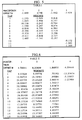
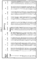
- FIGURES 5-8 are tables of coefficients used in exemplary embodiments of the networks illustrated in FIGURES 2-4.
- the invention will be described in the environment of in impulse noise or signal defect detection and correction system for processing composite video signals, however it will readily be recognized that the concepts may be applied to more general video signal processing applications.
- the assumption is made that the video signals are in sampled data format. in binary or PCM form, and with the samples occurring at a rate f S equal to four times the color subcarrier frequency.
- a neural network is a multi-layered combination of perceptrons.
- Each perceptron includes a summing node for summing a plurality of weighted samples, and applying an offset ⁇ . The output of the summing node is then applied to a non-linear circuit with a sigmoidal response.
- the function Zi is generally "S" shaped and is designated herein as a sigmoidal function.
- An alterntive sigmoidal function to equation (2) is the hyperbolic tangent, tanh(y i (x)/2).
- the perceptrons in a given layer all operate on the same set of input samples xj.
- the perceptrons in successive layers operate on output values generated by a prior layer of perceptrons.
- the architecture of the network that is the number of nodes, their interconnections and the external inputs are design choices as are the definitions of the desired output signals.
- the weights and offset values are determined in the laboratory in a training environment similar to the application in which the network will be implemented.
- the neural network will approximate a function which gives a statistical relationship between the inputs and outputs, such as the mean output given the input, the most probable output given the input, etc.
- the person training the network must choose a set of examples, the so-called "training set”, appropriately.
- the weights and thresholds of the network are adjusted to best approximate the training set according to some measure of the error of the approximation, most commonly the mean squared error on the training set.
- Methods for adjusting the weights and thresholds are currently a very active area of research, but almost all methods involve gradient descent. To do this, the gradient of the network's error for each example with respect to the weights and thresholds is computed. The errors and gradients for each example can then be averaged, giving the mean error and its gradient, and one can then apply classical optimization techniques, such as one of the conjugate gradient methods. Or one can perform a crude method of gradient descent called back-propagation.
- each weight and threshold is adjusted by simply adding to it a small constant multiplied by the negative of the derivative of the network error with respect to the weight or threshold in question.
- the error can be either the error for a particular example, the error averaged over some subset of the training set, or the error averaged over the whole training set.
- a common modification of this procedure is to compute a decaying average for each derivative, in which the average is taken over the recently computed errors, whether they are for single examples, or sets of examples. These averages are then used to adjust the weights and thresholds instead of the derivatives for the most recently computed error.
- the calculation of the gradient of the network's error with respect to the weights and thresholds is simplified by the structure of the network.
- the function computed by the network is a composition of several functions, each of which is realized by a layer in the network.
- the chain rule then gives the derivatives of the network's error with respect to this layer's weights and thresholds, but also it is useful for calculating the derivatives of the network's error with respect to the outputs of the nodes in the previous layer.
- This derivative for a node in the previous layer is the sum over the current layer's nodes of the current layer node's error multiplied by the derivative of the current layer node's output with respect to the previous layer node's output.
- FIGURE 1 shows a portion of a television signal processing system including several neural networks for performing various functions.
- a sampled data composite video signal is provided by a source 10.
- the source 10 may include an antenna, tuner and IF circuitry and a signal sampling circuit (e.g., an analog-to-digital converter).
- the source 10 may include a recorded medium and pickup circuitry.
- the signal provided by the source 10 is presumed to be susceptible of including defects such as impulse noise or signal drop outs.
- the signal from source 10 is coupled to a defect detector 11 and a defect corrector 12.
- the detector 11 generates a control signal which is applied to control the defect corrector 12.
- the defect corrector 12 includes a multiplexor and an interpolator. Signal from the source 10 is applied to one input of the multiplexor and to the interpolator. Interpolated samples generated by the interpolator are coupled to a second input of the multiplexor. The multiplexor is conditioned by the control signal to pass signal from the source 10 in the absence of signal defects and to pass interpolated samples on the occurrence of signal defects. The signal provided by the multiplexor is the signal output by the defect corrector 12. Note, respective compensating delay elements may have to be included in the defect corrector to temporally align the interpolated and real signal, and the control signal with corresponding defects.
- Output signal from the defect corrector 12 is applied to conventional video signal processing circuitry 13 which may include luminance/chrominance separating circuitry, chrominance demodulators, saturation-control, peaking, etc.
- the luminance and chrominance signals from the processor 13 are coupled to an interlace-to-noninterlace scan converter 15 and to a memory device 14.
- the memory device 14 provides samples to a neural network interpolating filter 16 which generates interstitial lines of video signal. These interstitial lines of signal are also applied to the scan converter 15 wherein real lines of video signal from the processor 13 are alternated with interpolated lines of video signal from the filter 16, which alternating lines are time compressed to form a twice rate non-interlaced signal.
- Output signal from the scan converter is provided to a display device (not shown).
- FIGURES 2 and 3 illustrate portions of the neural network defect detector 11.
- the neural network of FIGURE 2 operates on successive groupings of samples within a video line and is trained to recognize occurrences of defect like signal occurrences.
- the signal provided by this network is a sequence of pulses, one pulse for each defect-like occurrence.
- Certain images generate horizontal signal components similar to signal defects of the impulse/dropout type, which will be recognized as defects by the circuitry of FIGURE 2 and generate false detection pulses.
- these horizontal signal components are normally redundant line-to-line, that is, they are spatially correlated.
- Defects of the impulse/dropout type are random and spatially non-correlated.
- the circuitry of FIGURE 3 operates on a two-dimensional matrix of samples provided by the circuitry of FIGURE 2, and is trained to recognize only spatially non-correlated signal defect occurrences. While the output signal from the FIGURE 2 circuitry may be used directly as a defect indicating signal for controlling the defect corrector 12, inclusion of the FIGURE 3 circuitry greatly reduces the potential for false defect detection.
- signal from the source 10 is applied to a tapped delay line 20 having output taps A-I, each tap providing successive incremental delay of for example one signal sample period.
- Signals from the taps are applied to three similar perceptrons (PERCEPTRON 1, PERCEPTRON 2 AND PERCEPTRON 3).
- the signals from the taps A-I are applied to respective weighting circuits W1-W9 wherein these respective signals are scaled by different weighting values.
- the weighted signals are applied to a summing circuit 22.
- An offset value ⁇ is also applied to summing circuit 22 which generates successive samples y i (x) as defined by equation (2).
- the y i (x) samples are coupled to a nonlinear or sigmoidal element 24 which provides perceptron output samples according to the function defined by equation (1).
- Element 24 will typically be realized using a read-only-memory (ROM) which is preprogrammed with the function defined by equation 1.
- ROM read-only-memory
- the y i (x) values or sums are applied as address codes to the address input port of the ROM and Z i output values corresponding to the applied y i values are available at the ROM's output port.
- n-bit words y i , y i can assume 2 n -1 different values and hence 2 n -1 different ROM addresses.
- n is equal to, e.g., 6, there are 64 possible y i values.
- the number of stored values or effective addresses may be limited to a much smaller number.
- Samples are continuously loaded into the delay line 20 at the sample rate F S and the three perceptrons generate output values from groupings of nine successive samples. It has been determined for the defect detection function that it is only necessary to examine every other set of nine samples. That is, if the successive samples are numbered 1-15, the respective sets of nine samples processed by the three perceptrons are samples (1-9), (3-11), (5-13), (7-15), etc. As such the three perceptrons may be arranged to operate at one half the sample rate or F S /2.
- Output samples provided by PERCEPTRON 1, PERCEPTRON 2 AND PERCEPTRON 3 are coupled to a fourth perceptron 26 (PERCEPTRON 4) wherein they are respectively weighted, summed, offset and processed by the nonlinear sigmoidal element.
- PERCEPTRON 4 may be arranged to operate at one quarter of the input sample rate or F S /4.
- Output samples from the fourth perceptron are lowpass filtered (28) to remove high frequency components and then latched (30) to temporally stabilize output samples.
- Exemplary weighting coefficients and offset values utilized in the perceptrons of FIGURE 2 are listed in TABLE 1 wherein the taps 1-9 correspond to signals A-I respectively.
- the taps 10, 11 and 12 correspond to the outputs of PERCEPTRONS 1-3, respectively.
- the columns labeled 1-4 list the respective weights and offset values for PERCEPTRONS 1-4, respectively.
- FIGURE 3 illustrates a neural network for detecting non-spatially correlated pulses provided by the neural net of FIGURE 2.
- Samples from the latch 30 are coupled to a storage device 50 which concurrently provides five samples from each of three successive horizontal lines L n-1 , L n and L n+1 .
- These 15 samples S1-S15 are applied to each of three perceptrons P1, P2 and P3.
- These perceptrons are constructed similar to the PERCEPTRON 1 of FIGURE 2 except that there are 15 input signal paths with 15 weighting circuits rather than nine. It has been found that it is only necessary to examine alternate blocks of 15 samples, hence the perceptrons P1, P2 and P3 may be arranged to operate at half the sample rate of latch 30 or F S /8.
- Output samples from the perceptrons P1, P2 and P3 are applied to a three input perceptron P4 which provides the defect control signal applied to the defect corrector 12.
- Perceptron P4 is also similar to the perceptron 26 of FIGURE 2.
- Exemplary offset values and weighting coefficients applied to the perceptrons P1-P4 are listed in TABLE II.
- the taps labeled 1-15 correspond to samples S1-S15 respectively with respect to P1-P3.
- the taps labeled 1-3 correspond to the signals provided by the perceptrons P1-P3 respectively.
- FIGURE 4 illustrates an exemplary neural network which may be implemented as the interpolator in the defect corrector 12.
- This particular network is configured to provide interpolated samples for a composite NTSC video signal including a chrominance component modulated in quadrature on a subcarrier which alternates in phase from horizontal line-to-horizontal line.
- Interpolated samples are generated at the sample rate F S from five samples from each of two lines L n-2 , L n-1 preceding the current line L n and from five samples from each of two lines L n+1 , L n+2 , following the current line.
- the spatial point for which a current sample is interpolated is indicated by the open circle.
- the twenty samples used in the calculation are designated X1-X20.
- Input samples from the signal source 10 are applied to a storage element 70 which concurrently provides the 20 samples X1-X20 from segments of four horizontal lines. These twenty samples are coupled to each of 10 perceptrons P1A-P10A.
- the ten output samples F1-F10 generated by the respective perceptron P1A-P10A are applied to each of five perceptrons P1B-P5B.
- the five output samples F1A-F5A generated by the perceptrons P1B-P5B are coupled to a five input perceptron P6B which provides the interpolated sample.
- Each of the perceptrons in the FIGURE 4 embodiment are similar to PERCEPTRON 1 of FIGURE 2 modified to accommodate the number of input signals applied respectively thereto.
- the offset values and weighting coefficients for the perceptrons P1A-P10A are listed in TABLE IIIA.
- the offset values and weighting coefficients for perceptrons P1B-P6B are listed in TABLE IIIB.
- the tap numbers 1-20 correspond respectively to the samples designated X1-X20.
- the taps numbered 1-10 correspond to the output signals provided by the perceptrons P1A-P10A respectively.
- the taps numbered 1-5 correspond to output signals provided by the perceptrons P1B-P5B respectively.
- the interpolating neural network illustrated in FIGURE 4 appears to be relatively complex, however it provides excellent substitution samples.
- the complexity is a consequence of the signal being composite video. Separate, simpler interpolators operating on component signals may be implemented subsequent to luminance/chrominance separation. However, the overall complexity will be about the same, and due to effects of the defects on the luminance/chrominance separation circuitry, performance may be compromised.
- the FIGURE 4 circuitry is exemplary. Circuitry arranged to process a different matrix of samples are contemplated which include for example a neural network utilizing samples from lines L n-1 , L n and L n+1 . Regardless of the choice of the sample matrix processed either vertical or horizontal resolution will be somewhat compromised and this compromise is typically determinative of the circuitry selected for a particular application,
- the neural network of FIGURE 4 operates continuously and thus produces interpolated samples for every sample point in line L n .
- circuitry of this type is amenable to providing interstitial lines of video signal for interlace-to-noninterlace scan conversion.
- the matrix illustrated in element 70 would typically represent samples of a component signal.
- the line L n is an interstitial line being generated.
- Lines L n-1 and L n+1 represent lines from the current field of interlaced signal and lines L n-2 and L n+2 may represent lines from the previous field of interlaced signal.
- Nominally interlace-to-noninterlace scan converters use lines from the previous field for interstitial lines except where motion exists between fields/frames.
- interpolated values generated from samples within the current field are substituted for the interstitial line.
- An interpolating filter of the form shown in FIGURE 4 and operating on samples from the current and previous field may be arranged for generating interstitial lines. More typically however, the neural network interpolating filter will be arranged to process samples from two adjacent lines (L n-1 , L n+1 ) from the current field of interlaced video signal.
- a corresponding neural network interpolating filter for generating interstitial lines for scan conversion may take the form of the FIGURE 4 interpolator but with the number of inputs to the first layer of perceptrons (P1A-P10A) reduced to, e.g., ten (X6-X15).
- the weighting coefficients and offset values for the entire network will be determined by a training exercise.
Landscapes
- Engineering & Computer Science (AREA)
- Physics & Mathematics (AREA)
- Computer Graphics (AREA)
- Theoretical Computer Science (AREA)
- Signal Processing (AREA)
- Multimedia (AREA)
- General Health & Medical Sciences (AREA)
- Mathematical Physics (AREA)
- Data Mining & Analysis (AREA)
- Evolutionary Computation (AREA)
- Biophysics (AREA)
- Molecular Biology (AREA)
- Computing Systems (AREA)
- General Engineering & Computer Science (AREA)
- General Physics & Mathematics (AREA)
- Computational Linguistics (AREA)
- Software Systems (AREA)
- Biomedical Technology (AREA)
- Artificial Intelligence (AREA)
- Life Sciences & Earth Sciences (AREA)
- Health & Medical Sciences (AREA)
- Picture Signal Circuits (AREA)
- Television Systems (AREA)
Applications Claiming Priority (2)
| Application Number | Priority Date | Filing Date | Title |
|---|---|---|---|
| US617908 | 1984-06-06 | ||
| US61790890A | 1990-11-26 | 1990-11-26 |
Publications (3)
| Publication Number | Publication Date |
|---|---|
| EP0488003A2 EP0488003A2 (en) | 1992-06-03 |
| EP0488003A3 EP0488003A3 (en) | 1992-09-16 |
| EP0488003B1 true EP0488003B1 (en) | 1996-10-23 |
Family
ID=24475549
Family Applications (1)
| Application Number | Title | Priority Date | Filing Date |
|---|---|---|---|
| EP91119594A Expired - Lifetime EP0488003B1 (en) | 1990-11-26 | 1991-11-16 | Neural networks as for video signal processing |
Country Status (6)
| Country | Link |
|---|---|
| EP (1) | EP0488003B1 (es) |
| JP (1) | JP3563080B2 (es) |
| KR (1) | KR100216486B1 (es) |
| DE (1) | DE69122839T2 (es) |
| ES (1) | ES2094782T3 (es) |
| SG (1) | SG71656A1 (es) |
Families Citing this family (7)
| Publication number | Priority date | Publication date | Assignee | Title |
|---|---|---|---|---|
| US5376962A (en) * | 1993-03-31 | 1994-12-27 | Panasonic Technologies, Inc. | Neural network video image processor |
| EP0680224B1 (en) * | 1994-04-27 | 2002-11-13 | Co.Ri.M.Me. Consorzio Per La Ricerca Sulla Microelettronica Nel Mezzogiorno | Noise reduction filtering and scan rate conversion interpolation of digital video signals controlled by inter-field correlation information obtained using fuzzy logic inference |
| EP0684726B1 (en) * | 1994-04-27 | 2003-10-08 | Co.Ri.M.Me. Consorzio Per La Ricerca Sulla Microelettronica Nel Mezzogiorno | Fuzzy logic based scanning rate converter |
| DE19701909C2 (de) * | 1997-01-21 | 1999-02-25 | Siemens Ag | Verfahren und Schaltungsanordnung zur Flimmerreduktion eines Bildsignals |
| DE19802261A1 (de) * | 1998-01-22 | 1999-07-29 | Daimler Chrysler Ag | Verfahren zur Signalverarbeitung von Zeitfolgen digitalisierter Bilder |
| DE19805493A1 (de) * | 1998-02-11 | 1999-08-12 | Siemens Ag | Anordnung und Verfahren zur Unterdrückung von Zeilenflimmern auf Anzeigen mit zeitlich zeilenversetzter Teilbildanzeige |
| CN104735520A (zh) * | 2015-04-01 | 2015-06-24 | 百度在线网络技术(北京)有限公司 | 电视节目的播放控制方法、装置和电视机 |
-
1991
- 1991-11-16 ES ES91119594T patent/ES2094782T3/es not_active Expired - Lifetime
- 1991-11-16 DE DE69122839T patent/DE69122839T2/de not_active Expired - Fee Related
- 1991-11-16 EP EP91119594A patent/EP0488003B1/en not_active Expired - Lifetime
- 1991-11-16 SG SG1996003072A patent/SG71656A1/en unknown
- 1991-11-25 KR KR1019910021062A patent/KR100216486B1/ko not_active Expired - Fee Related
- 1991-11-25 JP JP33625291A patent/JP3563080B2/ja not_active Expired - Fee Related
Also Published As
| Publication number | Publication date |
|---|---|
| KR100216486B1 (ko) | 1999-08-16 |
| ES2094782T3 (es) | 1997-02-01 |
| EP0488003A3 (en) | 1992-09-16 |
| JPH0728769A (ja) | 1995-01-31 |
| DE69122839T2 (de) | 1997-03-13 |
| SG71656A1 (en) | 2000-04-18 |
| JP3563080B2 (ja) | 2004-09-08 |
| EP0488003A2 (en) | 1992-06-03 |
| DE69122839D1 (de) | 1996-11-28 |
| KR920011283A (ko) | 1992-06-27 |
Similar Documents
| Publication | Publication Date | Title |
|---|---|---|
| US5161014A (en) | Neural networks as for video signal processing | |
| EP0549681B1 (en) | Video image processing | |
| EP0037212B1 (en) | Methods and apparatuses for concealing error sample signals in digital television signals | |
| Plaziac | Image interpolation using neural networks | |
| Lukac | Adaptive color image filtering based on center-weighted vector directional filters | |
| US4788589A (en) | Method and apparatus for transmitting video data | |
| US4296436A (en) | Noise reducing system | |
| US4661853A (en) | Interfield image motion detector for video signals | |
| US5111511A (en) | Image motion vector detecting apparatus | |
| EP0393906B1 (en) | Video signal interpolation | |
| EP0396229A2 (en) | Spatial interpolation of digital video signals | |
| EP0488003B1 (en) | Neural networks as for video signal processing | |
| JPH03217184A (ja) | 動きベクトル検出装置 | |
| JPH0721946B2 (ja) | デイジタルテレビジヨン信号の誤り修正方法 | |
| GB2226207A (en) | Video signal processing for luminance-chrominance signal separator | |
| JP3291597B2 (ja) | 動き検出回路及びノイズ低減回路 | |
| US4636840A (en) | Adaptive luminance-chrominance separation apparatus | |
| JPH06326976A (ja) | 動き補償ビデオ信号処理方式 | |
| EP0561561A2 (en) | Digital video signal processing | |
| GB2202706A (en) | Video signal processing | |
| EP0680224A1 (en) | Fuzzy logic based filter architecture for video applications and corresponding filtering method | |
| JPH01269378A (ja) | 動き検出方法および動き検出器 | |
| Patterson et al. | Orbital mosaic IR image simulation and processing | |
| JP3214660B2 (ja) | 動きベクトル検出装置 | |
| Karloff et al. | A low-cost, real-time, hardware-based image demosaicking algorithm |
Legal Events
| Date | Code | Title | Description |
|---|---|---|---|
| PUAI | Public reference made under article 153(3) epc to a published international application that has entered the european phase |
Free format text: ORIGINAL CODE: 0009012 |
|
| AK | Designated contracting states |
Kind code of ref document: A2 Designated state(s): DE ES FR GB IT |
|
| PUAL | Search report despatched |
Free format text: ORIGINAL CODE: 0009013 |
|
| AK | Designated contracting states |
Kind code of ref document: A3 Designated state(s): DE ES FR GB IT |
|
| RAP1 | Party data changed (applicant data changed or rights of an application transferred) |
Owner name: RCA THOMSON LICENSING CORPORATION |
|
| 17P | Request for examination filed |
Effective date: 19930224 |
|
| 17Q | First examination report despatched |
Effective date: 19950102 |
|
| GRAG | Despatch of communication of intention to grant |
Free format text: ORIGINAL CODE: EPIDOS AGRA |
|
| GRAH | Despatch of communication of intention to grant a patent |
Free format text: ORIGINAL CODE: EPIDOS IGRA |
|
| GRAH | Despatch of communication of intention to grant a patent |
Free format text: ORIGINAL CODE: EPIDOS IGRA |
|
| GRAA | (expected) grant |
Free format text: ORIGINAL CODE: 0009210 |
|
| AK | Designated contracting states |
Kind code of ref document: B1 Designated state(s): DE ES FR GB IT |
|
| REF | Corresponds to: |
Ref document number: 69122839 Country of ref document: DE Date of ref document: 19961128 |
|
| ITF | It: translation for a ep patent filed | ||
| ET | Fr: translation filed | ||
| REG | Reference to a national code |
Ref country code: ES Ref legal event code: FG2A Ref document number: 2094782 Country of ref document: ES Kind code of ref document: T3 |
|
| PLBE | No opposition filed within time limit |
Free format text: ORIGINAL CODE: 0009261 |
|
| STAA | Information on the status of an ep patent application or granted ep patent |
Free format text: STATUS: NO OPPOSITION FILED WITHIN TIME LIMIT |
|
| 26N | No opposition filed | ||
| REG | Reference to a national code |
Ref country code: GB Ref legal event code: 732E |
|
| REG | Reference to a national code |
Ref country code: GB Ref legal event code: IF02 |
|
| REG | Reference to a national code |
Ref country code: FR Ref legal event code: D6 |
|
| REG | Reference to a national code |
Ref country code: GB Ref legal event code: 746 Effective date: 20030228 |
|
| PGFP | Annual fee paid to national office [announced via postgrant information from national office to epo] |
Ref country code: GB Payment date: 20061009 Year of fee payment: 16 |
|
| PGFP | Annual fee paid to national office [announced via postgrant information from national office to epo] |
Ref country code: FR Payment date: 20061012 Year of fee payment: 16 |
|
| PGFP | Annual fee paid to national office [announced via postgrant information from national office to epo] |
Ref country code: DE Payment date: 20061117 Year of fee payment: 16 |
|
| PGFP | Annual fee paid to national office [announced via postgrant information from national office to epo] |
Ref country code: ES Payment date: 20061129 Year of fee payment: 16 |
|
| PGFP | Annual fee paid to national office [announced via postgrant information from national office to epo] |
Ref country code: IT Payment date: 20061130 Year of fee payment: 16 |
|
| GBPC | Gb: european patent ceased through non-payment of renewal fee |
Effective date: 20071116 |
|
| PG25 | Lapsed in a contracting state [announced via postgrant information from national office to epo] |
Ref country code: DE Free format text: LAPSE BECAUSE OF NON-PAYMENT OF DUE FEES Effective date: 20080603 |
|
| REG | Reference to a national code |
Ref country code: FR Ref legal event code: ST Effective date: 20080930 |
|
| PG25 | Lapsed in a contracting state [announced via postgrant information from national office to epo] |
Ref country code: GB Free format text: LAPSE BECAUSE OF NON-PAYMENT OF DUE FEES Effective date: 20071116 |
|
| REG | Reference to a national code |
Ref country code: ES Ref legal event code: FD2A Effective date: 20071117 |
|
| PG25 | Lapsed in a contracting state [announced via postgrant information from national office to epo] |
Ref country code: FR Free format text: LAPSE BECAUSE OF NON-PAYMENT OF DUE FEES Effective date: 20071130 Ref country code: ES Free format text: LAPSE BECAUSE OF NON-PAYMENT OF DUE FEES Effective date: 20071117 |
|
| PG25 | Lapsed in a contracting state [announced via postgrant information from national office to epo] |
Ref country code: IT Free format text: LAPSE BECAUSE OF NON-PAYMENT OF DUE FEES Effective date: 20071116 |