EP0488056A1 - Verstärkerschaltung mit Entstörisolierung - Google Patents
Verstärkerschaltung mit Entstörisolierung Download PDFInfo
- Publication number
- EP0488056A1 EP0488056A1 EP91119867A EP91119867A EP0488056A1 EP 0488056 A1 EP0488056 A1 EP 0488056A1 EP 91119867 A EP91119867 A EP 91119867A EP 91119867 A EP91119867 A EP 91119867A EP 0488056 A1 EP0488056 A1 EP 0488056A1
- Authority
- EP
- European Patent Office
- Prior art keywords
- input terminal
- emitter follower
- terminal
- ground
- output terminal
- Prior art date
- Legal status (The legal status is an assumption and is not a legal conclusion. Google has not performed a legal analysis and makes no representation as to the accuracy of the status listed.)
- Granted
Links
- 238000002955 isolation Methods 0.000 claims abstract description 19
- 239000003990 capacitor Substances 0.000 claims description 23
- 230000005236 sound signal Effects 0.000 claims description 6
- 239000000872 buffer Substances 0.000 description 5
- 238000010586 diagram Methods 0.000 description 4
- 238000012986 modification Methods 0.000 description 1
- 230000004048 modification Effects 0.000 description 1
Images

Classifications
-
- H—ELECTRICITY
- H03—ELECTRONIC CIRCUITRY
- H03F—AMPLIFIERS
- H03F3/00—Amplifiers with only discharge tubes or only semiconductor devices as amplifying elements
-
- H—ELECTRICITY
- H03—ELECTRONIC CIRCUITRY
- H03F—AMPLIFIERS
- H03F3/00—Amplifiers with only discharge tubes or only semiconductor devices as amplifying elements
- H03F3/68—Combinations of amplifiers, e.g. multi-channel amplifiers for stereophonics
-
- H—ELECTRICITY
- H03—ELECTRONIC CIRCUITRY
- H03F—AMPLIFIERS
- H03F1/00—Details of amplifiers with only discharge tubes, only semiconductor devices or only unspecified devices as amplifying elements
- H03F1/30—Modifications of amplifiers to reduce influence of variations of temperature or supply voltage or other physical parameters
- H03F1/302—Modifications of amplifiers to reduce influence of variations of temperature or supply voltage or other physical parameters in bipolar transistor amplifiers
-
- H—ELECTRICITY
- H03—ELECTRONIC CIRCUITRY
- H03F—AMPLIFIERS
- H03F3/00—Amplifiers with only discharge tubes or only semiconductor devices as amplifying elements
- H03F3/45—Differential amplifiers
- H03F3/45071—Differential amplifiers with semiconductor devices only
- H03F3/45479—Differential amplifiers with semiconductor devices only characterised by the way of common mode signal rejection
Definitions
- the present invention relates to an isolation amplifier circuit, and particularly, to an isolation amplifier circuit employed for a noise cancel circuit, etc. of an audio apparatus such as a stereo sound system, etc.
- noise induced by an engine, etc. easily intrudes into an audio power amplifier since a car body is used as a ground portion of a circuit, whereby sound quality is deteriorated. Thus, it is required to cancel the noise on the way to the audio power amplifier.
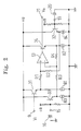
- Fig. 1 shows a conventional car audio circuit having a noise cancel circuit.
- the numeral 1 is a tuner deck having amplifiers 4 and 5 respectively connected to input terminals 2 and 3 to which audio signals of an L and R channels of a stereo are inputted. An output thereof is connected to input terminals 9 and 10 of a noise cancel circuit 8 through capacitors 6 and 7.
- the noise cancel circuit 8 is formed with an integrated circuit (IC).
- the input terminals 9 and 10 are connected to plus terminals of buffers 11 and 12.
- Output terminals of the buffers 11 and 12 are connected to plus terminals of operation amplifiers 13 and 14 through resistors R3 and R3'.
- Minus input terminals of the operation amplifiers 13 and 14 are connected to output terminals through resistors R2 and R2'.
- first common ground terminal 15 through resistors R1 and R1'.
- a capacitor 16 is connected to the first common ground terminal 15.
- the other end of the capacitor 16 is connected, together with the tuner block 1, to a car body 18 at a ground point 17.
- Plus input terminals of the operation amplifiers 13 and 14 are connected to a second common ground terminal 19 through resistors R4 and R4'.
- a capacitor 20 is connected to the second common ground terminal 19, a capacitor 20 is connected.
- the output terminals of the operation amplifiers 13 and 14 are connected to output terminals 21 and 22.
- the output terminals 21 and 22 are connected to audio power amplifiers 25 and 26 through capacitors 23 and 24.
- speakers 27 and 28 are connected as shown in the figure.
- Noise from a noise source 29 equivalently exists in the car body 1.
- the noise is divided into: noise which intrudes from the ground point 17 into the plus input terminal of the operation amplifier 13 for the L channel by way of the tuner deck 1, the amplifier 4, the terminal 9, and the buffer 11; noise which intrudes from the ground point 17 into the plus input terminal of the operation amplifier 14 for the R channel by way of the tuner deck 1, the amplifier 5, the terminal 10, and the buffer 12; noise which intrudes from the ground point 17 into the minus input terminal of the operation amplifier 13 for the L channel by way of the capacitor 16, the first common terminal 15, and the resistor R1; and noise which intrudes from the ground point 17 into the minus input terminal of the operation amplifier 14 for the R channel by way of the capacitor 16, the first common terminal 15, and the resistor R1'.
- noise cancel is interfered with when impedance connected to the first common ground terminal 15 is large.
- An object of the present invention is to provide an isolation amplifier circuit where a condition for noise cancel are fulfilled even if impedance connected to common ground terminals of an L and R channels is large.
- the isolation amplifier circuit is provided with: an operation amplifier having a first and second input terminals, an output terminal, and a feedback resistor for connecting the output terminal and second input terminal a first emitter follower, for inputting a signal, connected to the first input terminal; a second emitter follower connected between the output terminal and the feedback resistor; a third emitter follower connected between the second input terminal and a first ground impedance; a fourth emitter follower connected between the first input terminal and a second ground impedance; and means for making dynamic resistance of each of the first, second, third, and fourth emitter followers identical with one another.
- the isolation amplifier circuit for a car audio apparatus is provided with: an operation amplifier, for an L channel of a car stereo sound system, provided with a first and second input terminals, a first output terminal, and a first feedback resistor for connecting the first output terminal and a second output terminal; a first emitter follower, for inputting an L-channel audio signal, connected to the first input terminal; a second emitter follower connected between the first output terminal and the first feedback resistor; a third emitter follower connected between the second input terminal and a first ground impedance; a fourth emitter follower connected between the first input terminal and a second ground impedance; an operation amplifier, for an R channel of a car stereo apparatus, provided with a third and fourth input terminals, a second output terminal, and a second feedback resistor for connecting the second output terminal and the fourth input terminal; a fifth emitter follower, for inputting an R-channel audio signal, connected to the third input terminal; a sixth emitter follower connected between the second output terminal and
- the first and second ground impedances are equivalently converted into low impedance by the third and fourth emitter followers even if impedance thereof is high, impedance on the output side of the third and fourth emitter followers is not affected.
- a condition for canceling noise which intrudes into, for example, the first and second input terminals is never broken by the first and second ground impedances.
- an input signal is applied from an input terminal 9 to a plus input terminal (a first input terminal) of an operation amplifier 13 via an emitter follower 31 and a resistor R1.
- An output of the operation amplifier 13 is returned to a minus input terminal (a second input terminal) via an emitter follower 34 and a feedback resistor R4 connected to an output terminal as well as is directed to an output terminal 21.
- the minus input terminal is connected to a ground terminal 15 through a resistor R3 and an emitter follower 33.
- a capacitor 16 for grounding is connected.
- the plus input terminal is connected to a ground terminal 19 through a resistor R2 and a fourth emitter follower 32.
- To the ground terminal 19, a capacitor 20 is connected.
- capacity values of the capacitors 16 and 20 are small.
- impedance of the capacitors 16 and 20 is larger, sizes of the resistors R2 and R3 are hardly affected, since the impedance of each of the capacitors 16 and 20 is impedance-converted by the emitter followers 32 and 33 so that it becomes low on the output side (emitter side) of the emitter followers 32 and 33.
- the resistors R1, R2, R3, and R4 are connected to the emitter followers 31, 32, 33, and 34, respectively.
- the emitter followers 31, 32, 33, and 34 are provided to all of the resistors R1, R2, R3, and R4 in order to remove an influence of the dynamic resistance re.
- constant current sources 81, 82, 83, and 84 on the emitter side are identical in order to make identical dynamic resistors re1, re2, re3, and re4 of the emitter followers 31, 32, 33, and 34.
- the dynamic resistances are set by constant current sources, etc. provided to the emitters.
- an input signal from the input terminal 9 is inputted to the operation amplifier 13 through the emitter follower 31.
- the structure thereof is simpler compared to that of the conventional circuit (shown in Fig. 1) where the buffer 11 consists of an operation amplifier.
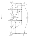
- Fig. 3 shows the above-described isolation amplifier circuit of Fig. 2 employed as a noise cancel circuit of a car audio apparatus.
- the numerals 4 and 25 are a preamplifier and an audio power amplifier, respectively. They are connected, together with a capacitor, to a car body 18 at ground points 17a and 17b.
- es a signal voltage outputted from an output terminal of the preamplifier 4
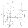
- Fig. 4 shows an embodiment where the isolation amplifier circuit of Fig. 2 is employed for both of the stereo L and R channels of a car audio apparatus.
- the ground terminals 15 and 19, and the third and fourth emitter followers 32 and 33 are used for both of the L and R channels.
- the numeral 13' is an operation amplifier for the R channel
- the numeral 33' is a fifth emitter follower to which an R-channel audio signal from an input terminal 10 is inputted
- the numeral 34' is a sixth emitter follower in a feedback path of the operation amplifier 13'.
- the capacitors 16 and 20 are connected to the ground terminals 15 and 19 in the above-described embodiments of Figs. 2, 3, and 4, it is not always necessary to connect capacitors to the ground terminals 15 and 19 in implementing the present invention.
- the ground terminal 15 may be connected through a line pattern. In that case, if a distance from the ground terminal 15 to a ground point is long, the line pattern has an adequate resistance, so that impedance becomes high. Thus, an implementation of the present invention is effective also in this case.
- the first and second ground impedances are equivalently converted into low impedance by the third and fourth emitter followers even if impedance thereof is high, impedance on the output side of the fourth emitter follower is not affected. Thus, a condition for canceling noise which intrudes into the first and second input terminals is never broken by the first and second ground impedances. Moreover, since the first and second impedances may be great, when capacitors are used as the first and second impedances, the capacity values of the capacitors can be small.
- the isolation amplifier circuit is employed for a noise cancel circuit of a car audio apparatus, high-quality sound is obtained which is not affected by noise from an engine, etc. and where there is no distortion.
- the whole circuit can be designed so as to be of simple structure.
Landscapes
- Engineering & Computer Science (AREA)
- Power Engineering (AREA)
- Amplifiers (AREA)
Applications Claiming Priority (2)
| Application Number | Priority Date | Filing Date | Title |
|---|---|---|---|
| JP2319999A JP2516706B2 (ja) | 1990-11-24 | 1990-11-24 | アンプ |
| JP319999/90 | 1990-11-24 |
Publications (2)
| Publication Number | Publication Date |
|---|---|
| EP0488056A1 true EP0488056A1 (de) | 1992-06-03 |
| EP0488056B1 EP0488056B1 (de) | 1996-01-17 |
Family
ID=18116623
Family Applications (1)
| Application Number | Title | Priority Date | Filing Date |
|---|---|---|---|
| EP91119867A Expired - Lifetime EP0488056B1 (de) | 1990-11-24 | 1991-11-21 | Verstärkerschaltung mit Entstörisolierung |
Country Status (5)
| Country | Link |
|---|---|
| US (1) | US5191298A (de) |
| EP (1) | EP0488056B1 (de) |
| JP (1) | JP2516706B2 (de) |
| KR (1) | KR0156942B1 (de) |
| DE (1) | DE69116526T2 (de) |
Cited By (3)
| Publication number | Priority date | Publication date | Assignee | Title |
|---|---|---|---|---|
| EP0809353A3 (de) * | 1996-05-20 | 1999-07-14 | Kabushiki Kaisha Toshiba | Verstärker zur Unterdrückung von Störgeräusch zwischen Schaltungssystemen |
| EP1052878A1 (de) * | 1999-05-10 | 2000-11-15 | Peugeot Citroen Automobiles SA | Vorrichtung zum Anschluss einer Quelle an eine Audioabstrahleinrichtung, insbesondere eines Kraftfahrzeuges |
| DE102009057225A1 (de) * | 2009-12-02 | 2011-08-04 | Sauermann, Gerd, Dipl.-Ing.(FH), 53117 | Spannungsakkurater Konstantstromverstärker |
Families Citing this family (5)
| Publication number | Priority date | Publication date | Assignee | Title |
|---|---|---|---|---|
| US8476010B2 (en) * | 2003-07-10 | 2013-07-02 | App Pharmaceuticals Llc | Propofol formulations with non-reactive container closures |
| JP2007088931A (ja) * | 2005-09-22 | 2007-04-05 | Mitsubishi Precision Co Ltd | アナログ・アイソレーション回路 |
| US8222590B2 (en) * | 2007-03-29 | 2012-07-17 | Nec Corporation | Signal amplifier for optical receiver circuit |
| US10044447B2 (en) * | 2016-04-04 | 2018-08-07 | Biosense Webster (Israel) Ltd. | Linear isolation amplifier with output DC voltage cancellation |
| CN116626327B (zh) * | 2023-04-28 | 2025-07-11 | 苏州东菱智能减振降噪技术有限公司 | 一种转速信号调节电路 |
Citations (3)
| Publication number | Priority date | Publication date | Assignee | Title |
|---|---|---|---|---|
| US3394269A (en) * | 1964-12-21 | 1968-07-23 | Navy Usa | Ground loop signal cancellation |
| US3947695A (en) * | 1974-10-21 | 1976-03-30 | The United States Of America As Represented By The Secretary Of The Department Of Transportation | Signal conditioner front-end |
| FR2614741A1 (fr) * | 1987-04-30 | 1988-11-04 | Sgs Thomson Microelectronics | Amplificateur d'audiofrequence du type dit symetrique pour recepteur radiophonique d'automobile |
Family Cites Families (3)
| Publication number | Priority date | Publication date | Assignee | Title |
|---|---|---|---|---|
| JPS56115012A (en) * | 1980-02-18 | 1981-09-10 | Hitachi Denshi Ltd | Feedback circuit for integrated circuit |
| US4378467A (en) * | 1980-07-01 | 1983-03-29 | Roanwell Corporation | Audio amplifier |
| JP2680569B2 (ja) * | 1986-10-17 | 1997-11-19 | 三洋電機株式会社 | 増幅器 |
-
1990
- 1990-11-24 JP JP2319999A patent/JP2516706B2/ja not_active Expired - Lifetime
-
1991
- 1991-11-21 EP EP91119867A patent/EP0488056B1/de not_active Expired - Lifetime
- 1991-11-21 DE DE69116526T patent/DE69116526T2/de not_active Expired - Fee Related
- 1991-11-21 US US07/795,432 patent/US5191298A/en not_active Expired - Lifetime
- 1991-11-22 KR KR1019910020863A patent/KR0156942B1/ko not_active Expired - Fee Related
Patent Citations (3)
| Publication number | Priority date | Publication date | Assignee | Title |
|---|---|---|---|---|
| US3394269A (en) * | 1964-12-21 | 1968-07-23 | Navy Usa | Ground loop signal cancellation |
| US3947695A (en) * | 1974-10-21 | 1976-03-30 | The United States Of America As Represented By The Secretary Of The Department Of Transportation | Signal conditioner front-end |
| FR2614741A1 (fr) * | 1987-04-30 | 1988-11-04 | Sgs Thomson Microelectronics | Amplificateur d'audiofrequence du type dit symetrique pour recepteur radiophonique d'automobile |
Cited By (5)
| Publication number | Priority date | Publication date | Assignee | Title |
|---|---|---|---|---|
| EP0809353A3 (de) * | 1996-05-20 | 1999-07-14 | Kabushiki Kaisha Toshiba | Verstärker zur Unterdrückung von Störgeräusch zwischen Schaltungssystemen |
| EP1052878A1 (de) * | 1999-05-10 | 2000-11-15 | Peugeot Citroen Automobiles SA | Vorrichtung zum Anschluss einer Quelle an eine Audioabstrahleinrichtung, insbesondere eines Kraftfahrzeuges |
| FR2793622A1 (fr) * | 1999-05-10 | 2000-11-17 | Peugeot Citroen Automobiles Sa | Dispositif de raccordement d'une source a un equipement de diffusion audiophonique notamment d'un vehicule automobile |
| DE102009057225A1 (de) * | 2009-12-02 | 2011-08-04 | Sauermann, Gerd, Dipl.-Ing.(FH), 53117 | Spannungsakkurater Konstantstromverstärker |
| DE102009057225B4 (de) * | 2009-12-02 | 2012-10-31 | Gerd Sauermann | Elektronische Leistungsverstärkerstufe und Leistungsverstärkerendstufe |
Also Published As
| Publication number | Publication date |
|---|---|
| DE69116526D1 (de) | 1996-02-29 |
| JP2516706B2 (ja) | 1996-07-24 |
| KR0156942B1 (ko) | 1998-12-15 |
| US5191298A (en) | 1993-03-02 |
| KR920011051A (ko) | 1992-06-27 |
| EP0488056B1 (de) | 1996-01-17 |
| JPH04192607A (ja) | 1992-07-10 |
| DE69116526T2 (de) | 1996-09-12 |
Similar Documents
| Publication | Publication Date | Title |
|---|---|---|
| US4414433A (en) | Microphone output transmission circuit | |
| JP4310383B2 (ja) | 差動オーディオ線受信器 | |
| JP3222149B2 (ja) | グランド・アイソレート回路 | |
| USRE37130E1 (en) | Signal conditioning apparatus | |
| EP0482291B1 (de) | Trennschaltung für ein Audiosystem | |
| EP0488056A1 (de) | Verstärkerschaltung mit Entstörisolierung | |
| JPH03802B2 (de) | ||
| US4626678A (en) | Light detecting circuit | |
| US4521741A (en) | Impedance transformer circuit | |
| CN1035858C (zh) | 具有高信号输出的汽车音响系统 | |
| EP0706729B1 (de) | Signalkonditionierungsgerät | |
| US4034166A (en) | Transmission networks for telephone system | |
| US5694081A (en) | Signal conditioning apparatus | |
| US6842525B1 (en) | Signal amplification circuit and process for neutralizing noise from a power supply voltage | |
| US4258329A (en) | Noise suppression system | |
| JP2523937B2 (ja) | 高周波信号分配回路 | |
| KR100539625B1 (ko) | 임피던스변환회로, 영상기기, 오디오기기 및 통신장치 | |
| US12542538B1 (en) | Low-noise short-offset transient electromagnetic receiving conditioning circuit and receiver | |
| JPH0326668Y2 (de) | ||
| JP2900394B2 (ja) | アイソレーション回路 | |
| JPS60191525A (ja) | コモンモ−ドノイズ減衰器 | |
| JP2658950B2 (ja) | 光アナログ伝送用受信回路 | |
| JP2538659Y2 (ja) | Fm受信機 | |
| GB2050771A (en) | Car-mounted audio equipment | |
| JPS6223137Y2 (de) |
Legal Events
| Date | Code | Title | Description |
|---|---|---|---|
| PUAI | Public reference made under article 153(3) epc to a published international application that has entered the european phase |
Free format text: ORIGINAL CODE: 0009012 |
|
| AK | Designated contracting states |
Kind code of ref document: A1 Designated state(s): DE FR GB IT NL |
|
| 17P | Request for examination filed |
Effective date: 19920427 |
|
| 17Q | First examination report despatched |
Effective date: 19940729 |
|
| GRAA | (expected) grant |
Free format text: ORIGINAL CODE: 0009210 |
|
| AK | Designated contracting states |
Kind code of ref document: B1 Designated state(s): DE FR GB IT NL |
|
| PG25 | Lapsed in a contracting state [announced via postgrant information from national office to epo] |
Ref country code: IT Free format text: LAPSE BECAUSE OF FAILURE TO SUBMIT A TRANSLATION OF THE DESCRIPTION OR TO PAY THE FEE WITHIN THE PRESCRIBED TIME-LIMIT;WARNING: LAPSES OF ITALIAN PATENTS WITH EFFECTIVE DATE BEFORE 2007 MAY HAVE OCCURRED AT ANY TIME BEFORE 2007. THE CORRECT EFFECTIVE DATE MAY BE DIFFERENT FROM THE ONE RECORDED. Effective date: 19960117 |
|
| ET | Fr: translation filed | ||
| REF | Corresponds to: |
Ref document number: 69116526 Country of ref document: DE Date of ref document: 19960229 |
|
| PG25 | Lapsed in a contracting state [announced via postgrant information from national office to epo] |
Ref country code: GB Effective date: 19961121 |
|
| PLBE | No opposition filed within time limit |
Free format text: ORIGINAL CODE: 0009261 |
|
| STAA | Information on the status of an ep patent application or granted ep patent |
Free format text: STATUS: NO OPPOSITION FILED WITHIN TIME LIMIT |
|
| 26N | No opposition filed | ||
| GBPC | Gb: european patent ceased through non-payment of renewal fee |
Effective date: 19961121 |
|
| PGFP | Annual fee paid to national office [announced via postgrant information from national office to epo] |
Ref country code: FR Payment date: 19991109 Year of fee payment: 9 |
|
| PGFP | Annual fee paid to national office [announced via postgrant information from national office to epo] |
Ref country code: DE Payment date: 19991119 Year of fee payment: 9 |
|
| PGFP | Annual fee paid to national office [announced via postgrant information from national office to epo] |
Ref country code: NL Payment date: 19991130 Year of fee payment: 9 |
|
| PG25 | Lapsed in a contracting state [announced via postgrant information from national office to epo] |
Ref country code: NL Free format text: LAPSE BECAUSE OF NON-PAYMENT OF DUE FEES Effective date: 20010601 |
|
| PG25 | Lapsed in a contracting state [announced via postgrant information from national office to epo] |
Ref country code: FR Free format text: LAPSE BECAUSE OF NON-PAYMENT OF DUE FEES Effective date: 20010731 |
|
| NLV4 | Nl: lapsed or anulled due to non-payment of the annual fee |
Effective date: 20010601 |
|
| PG25 | Lapsed in a contracting state [announced via postgrant information from national office to epo] |
Ref country code: DE Free format text: LAPSE BECAUSE OF NON-PAYMENT OF DUE FEES Effective date: 20010801 |
|
| REG | Reference to a national code |
Ref country code: FR Ref legal event code: ST |