EP0488350A2 - Procédé et dispositif pour la commande d'un moteur - Google Patents
Procédé et dispositif pour la commande d'un moteur Download PDFInfo
- Publication number
- EP0488350A2 EP0488350A2 EP91120488A EP91120488A EP0488350A2 EP 0488350 A2 EP0488350 A2 EP 0488350A2 EP 91120488 A EP91120488 A EP 91120488A EP 91120488 A EP91120488 A EP 91120488A EP 0488350 A2 EP0488350 A2 EP 0488350A2
- Authority
- EP
- European Patent Office
- Prior art keywords
- motor
- acceleration
- speed
- rotational speed
- rotational
- Prior art date
- Legal status (The legal status is an assumption and is not a legal conclusion. Google has not performed a legal analysis and makes no representation as to the accuracy of the status listed.)
- Withdrawn
Links
Images


Classifications
-
- G—PHYSICS
- G05—CONTROLLING; REGULATING
- G05B—CONTROL OR REGULATING SYSTEMS IN GENERAL; FUNCTIONAL ELEMENTS OF SUCH SYSTEMS; MONITORING OR TESTING ARRANGEMENTS FOR SUCH SYSTEMS OR ELEMENTS
- G05B19/00—Program-control systems
- G05B19/02—Program-control systems electric
- G05B19/18—Numerical control [NC], i.e. automatically operating machines, in particular machine tools, e.g. in a manufacturing environment, so as to execute positioning, movement or co-ordinated operations by means of program data in numerical form
- G05B19/19—Numerical control [NC], i.e. automatically operating machines, in particular machine tools, e.g. in a manufacturing environment, so as to execute positioning, movement or co-ordinated operations by means of program data in numerical form characterised by positioning or contouring control systems, e.g. to control position from one programmed point to another or to control movement along a programmed continuous path
- G05B19/21—Numerical control [NC], i.e. automatically operating machines, in particular machine tools, e.g. in a manufacturing environment, so as to execute positioning, movement or co-ordinated operations by means of program data in numerical form characterised by positioning or contouring control systems, e.g. to control position from one programmed point to another or to control movement along a programmed continuous path using an incremental digital measuring device
- G05B19/23—Numerical control [NC], i.e. automatically operating machines, in particular machine tools, e.g. in a manufacturing environment, so as to execute positioning, movement or co-ordinated operations by means of program data in numerical form characterised by positioning or contouring control systems, e.g. to control position from one programmed point to another or to control movement along a programmed continuous path using an incremental digital measuring device for point-to-point control
- G05B19/231—Numerical control [NC], i.e. automatically operating machines, in particular machine tools, e.g. in a manufacturing environment, so as to execute positioning, movement or co-ordinated operations by means of program data in numerical form characterised by positioning or contouring control systems, e.g. to control position from one programmed point to another or to control movement along a programmed continuous path using an incremental digital measuring device for point-to-point control the positional error is used to control continuously the servomotor according to its magnitude
- G05B19/232—Numerical control [NC], i.e. automatically operating machines, in particular machine tools, e.g. in a manufacturing environment, so as to execute positioning, movement or co-ordinated operations by means of program data in numerical form characterised by positioning or contouring control systems, e.g. to control position from one programmed point to another or to control movement along a programmed continuous path using an incremental digital measuring device for point-to-point control the positional error is used to control continuously the servomotor according to its magnitude with speed feedback only
-
- H—ELECTRICITY
- H02—GENERATION; CONVERSION OR DISTRIBUTION OF ELECTRIC POWER
- H02P—CONTROL OR REGULATION OF ELECTRIC MOTORS, ELECTRIC GENERATORS OR DYNAMO-ELECTRIC CONVERTERS; CONTROLLING TRANSFORMERS, REACTORS OR CHOKE COILS
- H02P23/00—Arrangements or methods for the control of AC motors characterised by a control method other than vector control
- H02P23/18—Controlling the angular speed together with angular position or phase
- H02P23/186—Controlling the angular speed together with angular position or phase of one shaft by controlling the prime mover
-
- H—ELECTRICITY
- H02—GENERATION; CONVERSION OR DISTRIBUTION OF ELECTRIC POWER
- H02P—CONTROL OR REGULATION OF ELECTRIC MOTORS, ELECTRIC GENERATORS OR DYNAMO-ELECTRIC CONVERTERS; CONTROLLING TRANSFORMERS, REACTORS OR CHOKE COILS
- H02P23/00—Arrangements or methods for the control of AC motors characterised by a control method other than vector control
- H02P23/20—Controlling the acceleration or deceleration
-
- G—PHYSICS
- G03—PHOTOGRAPHY; CINEMATOGRAPHY; ANALOGOUS TECHNIQUES USING WAVES OTHER THAN OPTICAL WAVES; ELECTROGRAPHY; HOLOGRAPHY
- G03G—ELECTROGRAPHY; ELECTROPHOTOGRAPHY; MAGNETOGRAPHY
- G03G2215/00—Apparatus for electrophotographic processes
- G03G2215/00172—Apparatus for electrophotographic processes relative to the original handling
- G03G2215/00177—Apparatus for electrophotographic processes relative to the original handling for scanning
- G03G2215/00181—Apparatus for electrophotographic processes relative to the original handling for scanning concerning the original's state of motion
- G03G2215/00185—Apparatus for electrophotographic processes relative to the original handling for scanning concerning the original's state of motion original at rest
Definitions
- the present invention relates generally to a method of and a device for driving and controlling a motor, and more particularly, to a method of and a device for driving and controlling a motor so adapted as to reduce the shock experienced by a motor and/or a load driven by the motor when the motor speed is varied (the motor is initiated, accelerated, decelerated or stopped).
- the acceleration of the motor (the slope of a line V-t in Fig. 2) changes during the deceleration.
- the acceleration (the slope of the line V-t) reaches its maximum at the time of starting the deceleration, and the acceleration (the slope of the line V-t) reaches its minimum immediately before the stop.
- the acceleration at the time of starting the deceleration must be very high.
- the acceleration at the time of starting the deceleration is low, it takes longer to stop the motor.
- the motor control device is a control device for, for example, a servomotor for driving an optical system in a copying machine
- the optical system in the copying machine includes members which cannot withstand the shock such as a halogen lamp for illuminating a document and a reflecting mirror and the members which cannot withstand the shock are liable to be, for example, damaged if the acceleration is largely varied.
- the conventional motor control device has the disadvantage in that it takes longer to vary the speed. Particularly it has the disadvantage in that it takes longer to carry out the deceleration control of the servomotor in a state where the optical system is returned. Therefore, it is difficult to increase the processing speed of the copying machine.
- the present invention has been made to solve the problem of the prior art and has for its object to provide a motor control device capable of efficiently varying the speed in a short time at a constant acceleration.
- Fig. 5 is a block diagram showing an example of the construction of a motor for driving an optical system 10 in a copying machine and its control circuit.
- the optical unit 10 is provided with an illuminating lamp 11 and a reflecting mirror 12. This optical unit 10 is fixed to a wire 13, and is moved forward in the direction indicated by an arrow A1 and is returned in the direction indicated by an arrow A2 by the wire 13.
- the wire 13 is stretched between two pulleys 14 and 15.
- the pulley 14 is rotated by a DC servomotor 1 to rotate the wire 13.
- a rotary encoder 2 serving as means for detecting the rotating state of the DC servomotor 1 for driving an optical system is connected to the axis of rotation of the DC servomotor 1.
- the rotary encoder 2 outputs pulses every time the DC servomotor 1 is rotated through a predetermined very small angle.
- B-phase and A-phase pulses, for example, which are equal in period and are 90° out of phase are outputted from the rotary encoder 2 in the present embodiment. Pulses having the respective phases, for example, 200 pulses are outputted by one rotation of the DC servomotor 1.
- the rotary encoder 2 may be replaced with another equipment for outputting pulses which are periodically synchronized with the rotation of the DC servomotor 1, for example, a frequency generator.
- a control circuit 3 includes a microcomputer 4, a memory 5, and a drive circuit 6.
- the microcomputer 4 calculates rotational speed data of the DC servomotor 1 and rotational position data ⁇ of the DC servomotor 1 on the basis of the pulses applied from the rotary encoder 2, and calculates a command speed V on the basis of an acceleration A stored in the memory 5, as described later.
- the command speed V calculated by the microcomputer 4 is applied to the drive circuit 6.
- the rotational speed of the DC servomotor 1 is controlled by the drive circuit 6.
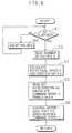
- Fig. 6 is a flow chart showing the contents of control of the microcomputer 4 shown in Fig. 5.
- the number of pulses applied from the rotary encoder 2 is counted by the microcomputer 4, and the number of pulses n in a predetermined very small time period ⁇ t is read in the microcomputer 4 for each time period ⁇ t (steps S1, S2 and S3).
- a rotational speed N of the servomotor 1 is calculated on the basis of the number of pulses n read per very small time period ⁇ t, and the rotational position data ⁇ of the motor is calculated (step S4).
- the rotational position data ⁇ can be found by multiplying an accumulated value of the number of pulses n by a pulse angle.
- the calculation may be done using a system disclosed in, for example, United States Patent Application Serial Number 07/550,722 which is a prior application of the present applicant.
- the microcomputer 4 carries out such control that the rotational speed N of the DC servomotor 1 reaches this command speed V. Therefore, a control voltage k (V - N) (where k is a proportional constant) proportional to the difference (V - N) between the actual rotational speed N of the DC servomotor 1 calculated in the step S4 and the above command speed V is applied to the drive circuit 6. Accordingly, control is carried out such that the rotational speed N of the motor 1 reaches the command speed V by the drive circuit 6 (step S6).
- the control voltage applied to the drive circuit 6 may be not the voltage k (V - N) proportional to the difference between the command speed V and the rotational speed N but a voltage obtained by adding a control element proportional to the difference between the signal phase of the command speed V and the signal phase of the rotational speed N to the above control voltage k (V - N) proportional to the difference in speed.
- Output pulses of the rotary encoder 2 are counted for each predetermined very small time period ⁇ t and are read in the microcomputer 4. Accordingly, the command speed V is varied (decreased or increased, for example) at the acceleration A under constant conditions as the servomotor 1 is rotated.
- the speed of the DC servomotor 1 can be varied (the DC servomotor 1 is initiated, accelerated, decelerated or stopped) at a constant acceleration, thereby to make it possible to reduce the shock experienced by the DC servomotor 1 or the optical system 10 in the copying machine which is driven by the motor 1 at the time of varying the speed and to carry out efficient control in a relatively short time.
- the acceleration A is stored in the memory 5, and the command speed V is calculated utilizing the acceleration A.
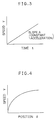
- a function based on a constant acceleration A for example, a function (characteristic curve) of the position ⁇ and the speed V as shown in Fig. 4 may be stored in the memory 5 to calculate the command speed V by applying the rotational position data ⁇ calculated to this characteristic curve.
- a plurality of accelerations A1, A2, A3, ... may be previously stored in the memory 5, and the acceleration used may be changed depending on the contents of control.
- A1 is taken as an acceleration used at the time of acceleration control
- A2 is taken as an acceleration used at the time of deceleration control.
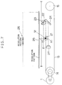
- Fig. 7 is an illustration showing the construction of an optical system in a copying machine and the construction of a position data detecting mechanism according to another embodiment of the present invention.
- the embodiment shown in Fig. 7 describes such construction as to detect position data of a load moved by a motor, that is, an optical system in place of the above described rotational position data ⁇ of the motor.
- the optical system is provided with a first frame 21 comprising an illuminating lamp 11 and a first mirror 12.
- the first frame 21 is fixed to a wire 13.
- the first frame 21 is moved forward in a direction indicated by an arrow A1 and is returned in the opposite direction by the wire 13.
- the optical system is provided with a second frame 22 moved by the wire 13.
- the second frame 22 comprises a second mirror 23 and a third mirror 24. Assuming that the first frame 21 is moved in the direction indicated by the arrow A1 at a speed of v, the second frame 22 is moved in the same direction at a speed of v/2, as is known.
- a document (not shown) mounted on a transparent platen 25 illuminated by the illuminating lamp 11 and a predetermined resolution pattern 26 affixed to, for example, a side part on the lower surface of the transparent platen 25 are introduced into a CCD 26 by the first mirror 12, the second mirror 23 and the third mirror 24.
- the wire 13 is stretched between two pulleys 14 and 15, and the pulley 14 is rotated by a DC servomotor 1.
- the resolution pattern 26 affixed to the side part on the lower surface of the transparent platen 25 is, for example, a pattern of equally spaced black and white stripes, and is affixed to the side part of the transparent platen 25 throughout in the direction of main scanning A1.
- This resolution pattern 26 may be an arbitrary pattern, for example, a pattern of black and white stripes which differ in thickness, for example, a bar code.
- the present position of the first frame 21 can be accurately detected.
- position data x of the optical system to be controlled may be detected on the basis of the resolution pattern 26 detected by the CCD 26 in place of the rotary encoder connected to the DC servomotor 1.
Landscapes
- Engineering & Computer Science (AREA)
- Power Engineering (AREA)
- Human Computer Interaction (AREA)
- Manufacturing & Machinery (AREA)
- Physics & Mathematics (AREA)
- General Physics & Mathematics (AREA)
- Automation & Control Theory (AREA)
- Control Of Electric Motors In General (AREA)
- Control Or Security For Electrophotography (AREA)
- Control Of Position Or Direction (AREA)
- Exposure Or Original Feeding In Electrophotography (AREA)
Applications Claiming Priority (2)
| Application Number | Priority Date | Filing Date | Title |
|---|---|---|---|
| JP34002590 | 1990-11-30 | ||
| JP340025/90 | 1990-11-30 |
Publications (2)
| Publication Number | Publication Date |
|---|---|
| EP0488350A2 true EP0488350A2 (fr) | 1992-06-03 |
| EP0488350A3 EP0488350A3 (en) | 1992-10-21 |
Family
ID=18333027
Family Applications (1)
| Application Number | Title | Priority Date | Filing Date |
|---|---|---|---|
| EP19910120488 Withdrawn EP0488350A3 (en) | 1990-11-30 | 1991-11-29 | Method of and device for driving and controlling a motor |
Country Status (2)
| Country | Link |
|---|---|
| EP (1) | EP0488350A3 (fr) |
| JP (1) | JPH0522975A (fr) |
Cited By (1)
| Publication number | Priority date | Publication date | Assignee | Title |
|---|---|---|---|---|
| DE19620706C1 (de) * | 1996-05-23 | 1997-07-24 | Thomas Dipl Ing Knauf | Numerisches Verfahren zur Regelung für lineare Regelvorgänge, insbesondere geeignet zur schnellen und exakten Lage- und Drehzahlregelung von Elektromotoren |
Families Citing this family (4)
| Publication number | Priority date | Publication date | Assignee | Title |
|---|---|---|---|---|
| DE69317815T2 (de) * | 1992-06-15 | 1998-12-10 | Mita Industrial Co., Ltd., Osaka | Papierfördervorrichtung |
| JP3544789B2 (ja) * | 1996-07-17 | 2004-07-21 | 株式会社リコー | モータ制御装置及び画像読み取り装置の走行体駆動装置 |
| JP4568343B2 (ja) * | 2008-04-03 | 2010-10-27 | ファナック株式会社 | 機械可動部の加減速制御方法 |
| JP6440984B2 (ja) * | 2014-07-22 | 2018-12-19 | ファナック株式会社 | 停止距離による加減速制御を行う数値制御装置 |
Family Cites Families (3)
| Publication number | Priority date | Publication date | Assignee | Title |
|---|---|---|---|---|
| JPS58151885A (ja) * | 1982-03-03 | 1983-09-09 | Hitachi Ltd | モ−タの位置制御方法 |
| JPS59175947A (ja) * | 1983-03-22 | 1984-10-05 | Toshiba Mach Co Ltd | トランスフア装置 |
| FR2624988B1 (fr) * | 1987-12-18 | 1990-08-31 | Bocher Noel | Dispositif d'asservissement d'un parametre, notamment de la position d'un moteur electrique |
-
1991
- 1991-11-29 EP EP19910120488 patent/EP0488350A3/en not_active Withdrawn
- 1991-11-29 JP JP3316906A patent/JPH0522975A/ja active Pending
Cited By (1)
| Publication number | Priority date | Publication date | Assignee | Title |
|---|---|---|---|---|
| DE19620706C1 (de) * | 1996-05-23 | 1997-07-24 | Thomas Dipl Ing Knauf | Numerisches Verfahren zur Regelung für lineare Regelvorgänge, insbesondere geeignet zur schnellen und exakten Lage- und Drehzahlregelung von Elektromotoren |
Also Published As
| Publication number | Publication date |
|---|---|
| JPH0522975A (ja) | 1993-01-29 |
| EP0488350A3 (en) | 1992-10-21 |
Similar Documents
| Publication | Publication Date | Title |
|---|---|---|
| US5047871A (en) | Direction scaling method and apparatus for image scanning resolution control | |
| US5671076A (en) | Image display device using vibrating mirror | |
| US4332461A (en) | Electrical drive for scanning optics in a continuously variable reduction copier | |
| KR960036273A (ko) | 고주파수 클럭을 이용한 스위치된 자기저항 드라이브용 각도 제어기 | |
| JPS6336240B2 (fr) | ||
| GB2127193A (en) | Control system for a serial printer | |
| US5250884A (en) | Drive controlling apparatus | |
| US4731657A (en) | Control apparatus | |
| US6906488B2 (en) | Position control system for use in driving system transmitting driving force of driving source to driven member through power transmission mechanism, image forming apparatus, position control method, program for performing the position control method, and storage medium having the program stored thereon | |
| EP0488350A2 (fr) | Procédé et dispositif pour la commande d'un moteur | |
| US4315199A (en) | Control circuit for a positioning device using a d-c motor | |
| EP0409185A2 (fr) | Méthode pour calculer la tension de commande d'un moteur et appareil pour commander le moteur avec cette méthode | |
| EP0082713B1 (fr) | Dispositif pour balayer un original pour copieurs à rapport d'agrandissement variable | |
| JP2738802B2 (ja) | キャリア・ジャム検出制御方法 | |
| US5941359A (en) | Positioning apparatus | |
| US5442267A (en) | Device for controlling the reverse rotation of a motor and method of judging time point where the motor is actually rotated in a reverse direction | |
| EP1719631B1 (fr) | Profile de vitesse pour moteur pas à pas avec S courbe dynamique | |
| US4864211A (en) | Drive control for DC electric motor | |
| US4110675A (en) | Return and position control for a DC servo system | |
| JP3710925B2 (ja) | 速度制限装置 | |
| EP0574931A1 (fr) | Dispositif pour commander la rotation en sens inverse d'un moteur et méthode pour déterminer l'instant ou le moteur effectivement en sens inverse | |
| JPH06113576A (ja) | モータ制御装置 | |
| JP3513350B2 (ja) | 画像読取装置 | |
| JP3716594B2 (ja) | 画像読取装置 | |
| JPH0764203A (ja) | モータの駆動制御方法および装置 |
Legal Events
| Date | Code | Title | Description |
|---|---|---|---|
| PUAI | Public reference made under article 153(3) epc to a published international application that has entered the european phase |
Free format text: ORIGINAL CODE: 0009012 |
|
| AK | Designated contracting states |
Kind code of ref document: A2 Designated state(s): DE FR GB IT |
|
| PUAL | Search report despatched |
Free format text: ORIGINAL CODE: 0009013 |
|
| AK | Designated contracting states |
Kind code of ref document: A3 Designated state(s): DE FR GB IT |
|
| 17P | Request for examination filed |
Effective date: 19921214 |
|
| 17Q | First examination report despatched |
Effective date: 19941209 |
|
| STAA | Information on the status of an ep patent application or granted ep patent |
Free format text: STATUS: THE APPLICATION IS DEEMED TO BE WITHDRAWN |
|
| 18D | Application deemed to be withdrawn |
Effective date: 19950410 |