EP0488421B1 - Dispositif d'emballage continu - Google Patents
Dispositif d'emballage continu Download PDFInfo
- Publication number
- EP0488421B1 EP0488421B1 EP91120662A EP91120662A EP0488421B1 EP 0488421 B1 EP0488421 B1 EP 0488421B1 EP 91120662 A EP91120662 A EP 91120662A EP 91120662 A EP91120662 A EP 91120662A EP 0488421 B1 EP0488421 B1 EP 0488421B1
- Authority
- EP
- European Patent Office
- Prior art keywords
- net
- cylindrical
- cylindrical net
- packing apparatus
- inner sliding
- Prior art date
- Legal status (The legal status is an assumption and is not a legal conclusion. Google has not performed a legal analysis and makes no representation as to the accuracy of the status listed.)
- Expired - Lifetime
Links
- 238000012856 packing Methods 0.000 title claims description 47
- 230000000903 blocking effect Effects 0.000 claims 4
- 238000010438 heat treatment Methods 0.000 claims 1
- 238000002844 melting Methods 0.000 claims 1
- 230000008018 melting Effects 0.000 claims 1
- 235000009508 confectionery Nutrition 0.000 description 5
- 239000000463 material Substances 0.000 description 3
- 239000000853 adhesive Substances 0.000 description 1
- 230000001070 adhesive effect Effects 0.000 description 1
- 230000003247 decreasing effect Effects 0.000 description 1
- 235000013399 edible fruits Nutrition 0.000 description 1
- 230000001788 irregular Effects 0.000 description 1
- 238000000034 method Methods 0.000 description 1
- 229920013716 polyethylene resin Polymers 0.000 description 1
- 238000004804 winding Methods 0.000 description 1
Images


Classifications
-
- B—PERFORMING OPERATIONS; TRANSPORTING
- B65—CONVEYING; PACKING; STORING; HANDLING THIN OR FILAMENTARY MATERIAL
- B65B—MACHINES, APPARATUS OR DEVICES FOR, OR METHODS OF, PACKAGING ARTICLES OR MATERIALS; UNPACKING
- B65B9/00—Enclosing successive articles, or quantities of material, e.g. liquids or semiliquids, in flat, folded, or tubular webs of flexible sheet material; Subdividing filled flexible tubes to form packages
-
- B—PERFORMING OPERATIONS; TRANSPORTING
- B65—CONVEYING; PACKING; STORING; HANDLING THIN OR FILAMENTARY MATERIAL
- B65B—MACHINES, APPARATUS OR DEVICES FOR, OR METHODS OF, PACKAGING ARTICLES OR MATERIALS; UNPACKING
- B65B9/00—Enclosing successive articles, or quantities of material, e.g. liquids or semiliquids, in flat, folded, or tubular webs of flexible sheet material; Subdividing filled flexible tubes to form packages
- B65B9/10—Enclosing successive articles, or quantities of material, in preformed tubular webs, or in webs formed into tubes around filling nozzles, e.g. extruded tubular webs
- B65B9/13—Enclosing successive articles, or quantities of material, in preformed tubular webs, or in webs formed into tubes around filling nozzles, e.g. extruded tubular webs the preformed tubular webs being supplied in a flattened state
Definitions
- the present invention relates to a continuous packing apparatus.
- a continuous packing apparatus including the features of the first portion of claim 1 is known form DE-A-2 517 214.
- the inner sliding member inserted in the cylindrical net is combined and interlocked with the outer support member, so that the cylindrical net can easily be supported and moved. Consequently, a series of packing operations can be performed.
- the inner sliding member may be formed so as to be vertically moved through the cylindrical net while expanding the same.
- Preferred examples of the shape of the inner sliding member include a cylinder integrated with a cone, the combinations of a cylinder and a hemisphere, a square pole and a square cone (of which corners are rounded off, for example, a square or rectangle), an elliptic cylinder and an elliptic cone, an elliptic cylinder and a semiellipse, a polygonal cylinder and a polygonal cone (of which corners are rounded off, for example, a regular or irregular polygonal cylinder), and the like.
- the inner sliding member is inserted in the cylindrical net and is vertically moved in the cylindrical net correspondingly to each step of the packing operations.
- the inner sliding member is directly or indirectly supported by the support member through the cylindrical net externally.
- the inner sliding member may directly be supported and lifted up through the cylindrical net by the support member (with which the inner sliding member comes in contact), and may then fall down by self-respect.
- the inner sliding member may indirectly be moved vertically by a magnetic force to be applied to the support member (with which the inner sliding member does not come in contact).
- the inner sliding member may directly be moved vertically through the cylindrical net by a roller as the support member (with which the inner sliding member comes in contact).
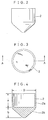
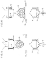
- an inner sliding member 2 having a smooth outer face shown in Figs. 2 to 4 and an operating device 17 shown in Fig. 5 as a continuous packing apparatus 15 for performing continuous packing by means of a cylindrical long packing net 1.
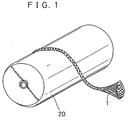
- the cylindrical long packing net 1 is supplied in the form of a thick string wound onto a roll 20.
- cylindrical long packing net 1 like a string is supplied from the lower roll 20 and is continuously pulled up to expand its aperture such that goods (confectionery) 16 to be packed can easily be put thereinto.
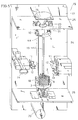
- the operating device 17 shown in Fig. 5 mainly comprises a ring-shaped support fitting 3, an elevator (with a built-in servomotor or air cylinder) 18 for causing the support fitting 3 to go up and down, a rail 19, a ring-shaped upper fitting 10, a holder 4 for pressing and supporting the cylindrical long packing net 1 together with the upper fitting 10 with the aperture of the cylindrical long packing net 1 expanded, a hopper 15 coaxially provided on the top of the holder 4, a stopper 5, a stator 11, a cutter 12, a heat source 13, and a saucer 14.
- the reference numeral 9 denotes a force pin erected on the support fitting 3.
- the reference numeral 4a denotes a flange of the holder 4 for pressing the aperture of the cylindrical long packing net 1 together with the upper fitting 10.
- the reference numeral 21 denotes a coil spring.
- the reference numeral 22 denotes a support shaft of the coil spring 21.
- the reference numeral 23 denotes a cylinder.
- the reference numeral 24 denotes a basic wall.
- the reference numeral 25 denotes an upper plate.
- the reference numeral 26 denotes a lower plate.
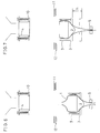
- the continuous packing apparatus 15 having the above-mentioned structure is operated by the operating device 17 as shown in Figs. 6 to 15.
- the cylindrical long packing net 1 supplied from the roll 20 has its aperture slightly expanded by inserting the inner sliding member 2 therein.
- the inner sliding member 2 is supported by the support fitting 3 through the cylindrical long packing net 1 externally.
- the support fitting 3 is pushed up to a constant height h together with the cylindrical long packing net 1 along the rail 19 by means of the elevator 18.
- the cylindrical long packing net 1 is fixed by the stopper 5. Sliding is caused between the cylindrical long packing net 1 and the inner sliding member 2, so that the aperture of the cylindrical long packing net 1 is greatly expanded in order to be easily fixed to the holder 4.
- the stopper 5 is opened and the cylindrical long packing net 1 having the aperture expanded is pulled up to a height H at which the upper fitting 10 is pushed up. Then, the elevator 18 falls down so that the cylindrical long packing net 1 is interposed between the upper fitting 10 and the holder 4 through which the goods (confectionery) 16 to be packed pass. Thereafter, the inner sliding member 2 slides down through the cylindrical long packing net 1 as shown in Fig. 9, and returns to a position in Fig. 6 as shown in Fig. 10.
- the middle portion of the cylindrical long packing net 1 having no inner sliding member 2 is held by the stator 11 (Fig. 11), and is then cut by the cutter 12 (Fig. 12). A cut portion is melted and sealed by the heat source 13. Consequently, the cylindrical long packing net 1 is transformed into a constant slender bag (see Fig. 13).
- a given quantity of goods (confectionery) 16 to be packed are put into the cylindrical long packing net 1 through the holder 4 as shown in Fig. 14, the cylindrical long packing net 1 is supported by the saucer 14 transferred in a transverse direction as shown in Fig. 15.
- the upper fitting 10 is lifted up by the cylinder 23 through the support shaft 22, so that the cylindrical long packing net 1 is removed from the upper fitting 10. Consequently, the state shown in Fig. 6 is returned.
- the goods 16 can also be packed by continuous operations with each means provided on the circumference differently from the operating device shown in Fig. 5.
- the goods 16 can be packed by the cylindrical long packing net 1 with the use of the inner sliding member 2 automatically, continuously and very quickly.
- Inner sliding member 2 (see Fig. 4) Same diameter portion a 6.5 cm Slanting portion b 8.0 cm Diameter D 13.0 cm Material Al (NiP treatment)
- Packing net 1 (see Fig. 1) Strand size 6 mm Mesh 5 mm x 5 mm Overall size in a natural state about 20 cm ⁇ Material Polyethylene resin
- Goods 16 to be packed Diameter of confectionery (drops) about 3 cm iv) Others h 10 cm (Fig. 7) H 35 cm (Fig. 8) c 15 cm (Fig. 12) m 15.5 cm (Fig. 12)
Landscapes
- Engineering & Computer Science (AREA)
- Mechanical Engineering (AREA)
- Containers And Plastic Fillers For Packaging (AREA)
- Supplying Of Containers To The Packaging Station (AREA)
Claims (6)
- Un dispositif d'empaquetement continu comprenant: une source (20) fournissant un filet cylindrique pour fournir un filet d'empaquetement (1) long cylindrique;
des moyens (2, 3, 5, 18, 19) pour déplacer le filet cylindrique et pour supporter à l'extérieur le filet cylindrique (1) fourni à partir de la source (20) de fourniture du filet cylindrique pour déplacer le même vers l'haut;
un élément de support supérieur (4, 4a, 10) pour supporter l'extrémité supérieure du filet cylindrique (1), quand il est déplacé vers l'haut, avec l'ouverture du filet cylindrique (1) en position d'ouverture;
des moyens (11, 12, 13) pour former des sacs de filets pour fixer d'une façon amovible la portion moyenne du filet cylindrique (1) quand il est déplacé vers l'haut, le moyen (11, 12, 13) de formation du sac en filet étant adapté de façon à couper une portion juste au dessous d'une position de fixage et pour bloquer une portion coupée supérieure de façon à former un sac en filet, et
une trémie (15) pour mettre des objets à être empaquetés dans le sac en filet (1) à travers l'ouverture de son extrémité supérieure;
des moyens (2, 3, 5, 18, 19) de mouvement d'un filet cylindrique comprenant un élément intérieur coulissant (2) à être introduit dans le filet cylindrique (1) de façon à être déplacé verticalement, un élément de support (3) pour supporter extérieurement l'élément coulissant intérieur (2) à travers le filet cylindrique (1) avec l'élément coulissant intérieur (2) introduit dans le filet cylindrique (1) et un élément mobile (18, 19) pour soulever l'élément de support (3),
caractérisé en ce que l'élément de support supérieur (4, 4a, 10) comporte un élément portant cylindrique (4), une bride extérieure (4a) formée sur l'extrémité inférieure de l'élément portant (4), et une armature (10) conformée en annueau, montée sur la bride (4a) dans une position de compression et de transmission cinématique pour comprimer et supporter l'ouverture de l'extrémité supérieure du filet cylindrique (1) avec la bride (4a). - Un dispositif d'empaquetement continu d'après la revendication 1, dans lequel l'élément intérieur coulissant (2) présente une portion cylindrique verticale (2a) et une portion conique invertie (2b) qui se prolonge, d'une seule pièce, vers le bas à partir de la portion verticale cylindrique.
- Un dispositif d'empaquetement continu d'après les revendications 1 ou 2, dans lequel les moyens (2, 3, 5, 18, 19) de déplacement du filet cylindrique comportent en outre un élément d'arrêt (5) pour fixer d'une façon forcée la portion inférieure d'un filet cylindrique (1) dans son état initial dans lequel le filet cylindrique (1) est déplacé vers l'haut.
- Un dispositif d'empaquetement continu d'après une ou plusieures des revendications précédentes, dans lequel les moyens (11, 12, 13) qui forment le sac en filet comportent un stator (11) pour fixer amoviblement la portion moyenne du filet cylindrique (1) déplacé vers l'haut, un organe de coupe (12) pour couper une portion juste au dessous de la position de fixage, et des moyens de blocage (13) pour bloquer une portion coupée supérieure.
- Un dispositif d'empaquetement continu d'après la revendication 4, dans lequel les moyens de blocage (13) comportent un dispositif de chauffage pour chauffer et faire fondre la portion supérieure coupée du filet cylindrique (1) et pour solidifier integralement le même.
- Un dispositif d'empaquetement continu d'après une ou plusieures des revendications précédentes, dans lequel l'élément de déplacement (18, 19) comporte un rail verticale (19) et un élévateur (18) pour porter l'élément de support (3) et pour déplacer verticalement le même le long du rail verticale (19) en vertu d'un auto-mouvement.
Applications Claiming Priority (2)
| Application Number | Priority Date | Filing Date | Title |
|---|---|---|---|
| JP2339931A JP2650115B2 (ja) | 1990-11-30 | 1990-11-30 | 連続包装装置 |
| JP339931/90 | 1990-11-30 |
Publications (2)
| Publication Number | Publication Date |
|---|---|
| EP0488421A1 EP0488421A1 (fr) | 1992-06-03 |
| EP0488421B1 true EP0488421B1 (fr) | 1995-02-01 |
Family
ID=18332116
Family Applications (1)
| Application Number | Title | Priority Date | Filing Date |
|---|---|---|---|
| EP91120662A Expired - Lifetime EP0488421B1 (fr) | 1990-11-30 | 1991-12-02 | Dispositif d'emballage continu |
Country Status (9)
| Country | Link |
|---|---|
| US (1) | US5172536A (fr) |
| EP (1) | EP0488421B1 (fr) |
| JP (1) | JP2650115B2 (fr) |
| KR (1) | KR920009665A (fr) |
| CN (1) | CN1026970C (fr) |
| AU (1) | AU649378B2 (fr) |
| DE (1) | DE69107179D1 (fr) |
| ES (1) | ES2067130T3 (fr) |
| TW (1) | TW197401B (fr) |
Families Citing this family (23)
| Publication number | Priority date | Publication date | Assignee | Title |
|---|---|---|---|---|
| DE4132852A1 (de) * | 1991-06-07 | 1992-12-10 | Windmoeller & Hoelscher | Verfahren zum herstellen, befuellen und verschliessen von saecken |
| ES2122869B1 (es) * | 1995-05-16 | 1999-06-16 | Daumar Talleres | Procedimiento para obtener paquetes llenos con productos, mediante tubo de malla continuo. |
| ES2127666B1 (es) * | 1995-09-22 | 1999-12-01 | Gimar Sa | Procedimiento de envasado de productos en bolsas de malla tubular. |
| US5847949A (en) * | 1997-10-07 | 1998-12-08 | Lucent Technologies Inc. | Boost converter having multiple outputs and method of operation thereof |
| EP1138596A1 (fr) * | 1999-03-19 | 2001-10-04 | Christian Reitterer | Produit de nettoyage en morceaux et emballage, ainsi que machine et procédé d'emballage |
| US20030208991A1 (en) * | 2002-05-08 | 2003-11-13 | Cad Industries, Inc. | Method and apparatus for product packaging |
| US20080110133A1 (en) * | 2006-08-16 | 2008-05-15 | Lorenzi Thomas E | Flexible Container Filling Device |
| US7441386B2 (en) * | 2006-10-27 | 2008-10-28 | Poly-Clip System Corp. | Apparatus for forming tubes in nets |
| CN100998300B (zh) * | 2007-01-04 | 2010-05-19 | 中国林业科学研究院林业研究所 | 轻基质网袋容器包装系统 |
| CN102303726B (zh) * | 2011-08-26 | 2013-11-06 | 上海宏曲电子科技有限公司 | 管状材料包装的控制装置 |
| CN102320390A (zh) * | 2011-08-26 | 2012-01-18 | 上海宏曲电子科技有限公司 | 管状材料包装的开口端形状保持装置 |
| CN102951306B (zh) * | 2011-08-26 | 2016-05-04 | 上海宏曲电子科技有限公司 | 管状材料的枕式包装装置 |
| CN102320391B (zh) * | 2011-08-26 | 2015-02-11 | 上海宏曲电子科技有限公司 | 管状材料包装的开口端固定装置 |
| CN102343990B (zh) * | 2011-08-26 | 2014-08-13 | 上海宏曲电子科技有限公司 | 管状材料包装的下封切装置 |
| CN102424149B (zh) * | 2011-08-26 | 2015-04-15 | 上海宏曲电子科技有限公司 | 管状材料包装的管状材料拉动装置 |
| CN103231818B (zh) * | 2013-04-23 | 2015-11-11 | 无锡市飞云球业有限公司 | 一种钢球自动包装装置 |
| CN106395005B (zh) * | 2016-11-30 | 2018-09-07 | 袁伟宏 | 一种塞心式球珠开膜装置 |
| CN106742200B (zh) * | 2017-01-11 | 2019-03-05 | 厦门南超机械有限公司 | 一种水果包装设备及方法 |
| CN107963267B (zh) * | 2017-11-22 | 2019-09-13 | 夏长峰 | 一种水果自动包装机 |
| CN108974431B (zh) * | 2018-08-02 | 2023-04-28 | 厦门理工学院 | 一种连续套网装置及套网方式 |
| CN109673344B (zh) * | 2019-01-28 | 2021-05-07 | 西安交通大学 | 一种苹果自动套袋装置 |
| CN111977048A (zh) * | 2020-07-13 | 2020-11-24 | 刘昕 | 一种空心筒形物品自动包装机 |
| CN116654355B (zh) * | 2023-07-24 | 2023-09-26 | 成都工业学院 | 一种石榴包装装置 |
Family Cites Families (10)
| Publication number | Priority date | Publication date | Assignee | Title |
|---|---|---|---|---|
| US2847806A (en) * | 1955-06-16 | 1958-08-19 | Wang Herman | Packing machines |
| US3070927A (en) * | 1959-12-30 | 1963-01-01 | Lundahl Lennart Viktor Samuel | Method of and apparatus for making and filling flexible-walled tubes |
| US3812642A (en) * | 1970-12-21 | 1974-05-28 | Industrial Knitting | Method and apparatus for packaging a product |
| JPS4837287A (fr) * | 1971-09-14 | 1973-06-01 | ||
| DE2517214A1 (de) * | 1975-04-16 | 1976-10-21 | Akira Hirai | Vorrichtung zur herstellung von verpackungsbeuteln aus einem schlauchartigen netzwerk |
| JPS526293A (en) * | 1975-07-03 | 1977-01-18 | Naoji Otake | Packaging method with flexible pipe |
| JPS5256689A (en) * | 1975-11-04 | 1977-05-10 | Teijin Seiki Co Ltd | Packing method |
| JPS5264385A (en) * | 1975-11-20 | 1977-05-27 | Toshiba Mach Co Ltd | Method and apparatsu for packaging |
| DE2807769A1 (de) * | 1978-02-23 | 1979-08-30 | Pack Verpackungsmaschinen Wern | Verfahren und vorrichtung zum verpacken von schuett- und stueckfoermigem gut |
| US4947625A (en) * | 1988-11-14 | 1990-08-14 | Zike Donald R | Bag-forming and filling apparatus and process |
-
1990
- 1990-11-30 JP JP2339931A patent/JP2650115B2/ja not_active Expired - Fee Related
-
1991
- 1991-11-27 US US07/798,909 patent/US5172536A/en not_active Expired - Fee Related
- 1991-11-29 KR KR1019910021634A patent/KR920009665A/ko not_active Withdrawn
- 1991-11-29 AU AU88282/91A patent/AU649378B2/en not_active Ceased
- 1991-11-30 CN CN91111916A patent/CN1026970C/zh not_active Expired - Fee Related
- 1991-12-02 DE DE69107179T patent/DE69107179D1/de not_active Expired - Lifetime
- 1991-12-02 ES ES91120662T patent/ES2067130T3/es not_active Expired - Lifetime
- 1991-12-02 EP EP91120662A patent/EP0488421B1/fr not_active Expired - Lifetime
-
1992
- 1992-07-08 TW TW081105406A patent/TW197401B/zh active
Also Published As
| Publication number | Publication date |
|---|---|
| JPH04242504A (ja) | 1992-08-31 |
| AU8828291A (en) | 1992-06-04 |
| EP0488421A1 (fr) | 1992-06-03 |
| CN1026970C (zh) | 1994-12-14 |
| CN1062701A (zh) | 1992-07-15 |
| JP2650115B2 (ja) | 1997-09-03 |
| KR920009665A (ko) | 1992-06-25 |
| ES2067130T3 (es) | 1995-03-16 |
| TW197401B (fr) | 1993-01-01 |
| US5172536A (en) | 1992-12-22 |
| AU649378B2 (en) | 1994-05-19 |
| DE69107179D1 (de) | 1995-03-16 |
Similar Documents
| Publication | Publication Date | Title |
|---|---|---|
| EP0488421B1 (fr) | Dispositif d'emballage continu | |
| EP3784576B1 (fr) | Emballage plié | |
| CA2857514C (fr) | Procede et machines pour integration de parties individuelles dans des recipients composites | |
| US3405744A (en) | Method and apparatus for packing material into containers | |
| KR102201339B1 (ko) | 종이상자 제조 시스템 | |
| EP0313421A2 (fr) | Réceptacle muni d'un dispositif de distribution de sacs de garniture | |
| EP0471670A4 (en) | Nested plastic bags, method of manufacture, and apparatus for manufacturing | |
| US5106449A (en) | Apparatus for forming container structures | |
| US6832425B2 (en) | Gasket singulation and insertion apparatus and methods | |
| JP2008518854A (ja) | 流動可能なダンネージの自動分配システム及び方法 | |
| US6560948B1 (en) | Tear-off cushions of loose fill packing material, and machine and method for making the same | |
| US2934872A (en) | Apparatus for packaging an edible article | |
| CN1198712C (zh) | 用于制造裹压货物的装置 | |
| EP0743251B1 (fr) | Procèdé pour obtenir des paquets remplis de produits au moyen d'un filet tubulaire continu | |
| CN202011844U (zh) | 一种工业粉状炸药装药机组 | |
| EP0742149B1 (fr) | Procédé pour obtenir des sacs remplis avec des produits à partir d'une provision de filet tubulaire | |
| JPH0851859A (ja) | 茸栽培用ブロックの製造装置 | |
| US20240099943A1 (en) | Method, machine and plant for the production of pasty or semisolid cosmetic products with a relief surface finishing | |
| JP2759619B2 (ja) | 菌床栽培用の培養容器の製造方法およびその装置 | |
| JP2799967B2 (ja) | 物品の箱詰装置 | |
| JP3053858U (ja) | シート材充填装置 | |
| US20040050021A1 (en) | Cushions of loose fill packing material | |
| US20200317416A1 (en) | Grouped screw bunch and related method and machine for production of the same | |
| JPH0692309A (ja) | 連続包装方法とその装置 | |
| JPS6367216A (ja) | フル−ツ包装材被覆装置 |
Legal Events
| Date | Code | Title | Description |
|---|---|---|---|
| PUAI | Public reference made under article 153(3) epc to a published international application that has entered the european phase |
Free format text: ORIGINAL CODE: 0009012 |
|
| AK | Designated contracting states |
Kind code of ref document: A1 Designated state(s): DE ES FR IT NL |
|
| 17P | Request for examination filed |
Effective date: 19921110 |
|
| 17Q | First examination report despatched |
Effective date: 19930921 |
|
| GRAA | (expected) grant |
Free format text: ORIGINAL CODE: 0009210 |
|
| AK | Designated contracting states |
Kind code of ref document: B1 Designated state(s): DE ES FR IT NL |
|
| PG25 | Lapsed in a contracting state [announced via postgrant information from national office to epo] |
Ref country code: IT Free format text: LAPSE BECAUSE OF FAILURE TO SUBMIT A TRANSLATION OF THE DESCRIPTION OR TO PAY THE FEE WITHIN THE PRE;WARNING: LAPSES OF ITALIAN PATENTS WITH EFFECTIVE DATE BEFORE 2007 MAY HAVE OCCURRED AT ANY TIME BEFORE 2007. THE CORRECT EFFECTIVE DATE MAY BE DIFFERENT FROM THE ONE RECORDED.SCRIBED TIME-LIMIT Effective date: 19950201 Ref country code: FR Effective date: 19950201 Ref country code: NL Effective date: 19950201 |
|
| REF | Corresponds to: |
Ref document number: 69107179 Country of ref document: DE Date of ref document: 19950316 |
|
| REG | Reference to a national code |
Ref country code: ES Ref legal event code: FG2A Ref document number: 2067130 Country of ref document: ES Kind code of ref document: T3 |
|
| PG25 | Lapsed in a contracting state [announced via postgrant information from national office to epo] |
Ref country code: DE Effective date: 19950503 |
|
| EN | Fr: translation not filed | ||
| NLV1 | Nl: lapsed or annulled due to failure to fulfill the requirements of art. 29p and 29m of the patents act | ||
| PLBE | No opposition filed within time limit |
Free format text: ORIGINAL CODE: 0009261 |
|
| STAA | Information on the status of an ep patent application or granted ep patent |
Free format text: STATUS: NO OPPOSITION FILED WITHIN TIME LIMIT |
|
| 26N | No opposition filed | ||
| PGFP | Annual fee paid to national office [announced via postgrant information from national office to epo] |
Ref country code: ES Payment date: 19981207 Year of fee payment: 8 |
|
| PG25 | Lapsed in a contracting state [announced via postgrant information from national office to epo] |
Ref country code: ES Free format text: LAPSE BECAUSE OF NON-PAYMENT OF DUE FEES Effective date: 20001203 |
|
| REG | Reference to a national code |
Ref country code: ES Ref legal event code: FD2A Effective date: 20010113 |