EP0488439B1 - Appareil permettant à la pâte de lever, comportant un transporteur sans fin et support s'y rapportant - Google Patents
Appareil permettant à la pâte de lever, comportant un transporteur sans fin et support s'y rapportant Download PDFInfo
- Publication number
- EP0488439B1 EP0488439B1 EP91202970A EP91202970A EP0488439B1 EP 0488439 B1 EP0488439 B1 EP 0488439B1 EP 91202970 A EP91202970 A EP 91202970A EP 91202970 A EP91202970 A EP 91202970A EP 0488439 B1 EP0488439 B1 EP 0488439B1
- Authority
- EP
- European Patent Office
- Prior art keywords
- carrier
- conveyor
- dough
- bearing pins
- transverse wall
- Prior art date
- Legal status (The legal status is an assumption and is not a legal conclusion. Google has not performed a legal analysis and makes no representation as to the accuracy of the status listed.)
- Expired - Lifetime
Links
- 239000000969 carrier Substances 0.000 title claims abstract description 19
- 238000006073 displacement reaction Methods 0.000 description 2
- 238000005096 rolling process Methods 0.000 description 2
- 230000000694 effects Effects 0.000 description 1
Images

Classifications
-
- A—HUMAN NECESSITIES
- A21—BAKING; EDIBLE DOUGHS
- A21C—MACHINES OR EQUIPMENT FOR MAKING OR PROCESSING DOUGHS; HANDLING BAKED ARTICLES MADE FROM DOUGH
- A21C13/00—Provers, i.e. apparatus permitting dough to rise
- A21C13/02—Provers, i.e. apparatus permitting dough to rise with endless conveyors, e.g. for moving the dough pieces progressively through the prover
Definitions
- the invention relates to a proving chamber comprising a chamber and a conveying system therein consisting of at least one endless conveyor running in an almost vertical plane and being guided therein over a number of return rollers, at which the conveyor serves for supporting a number of carriers each consisting of an almost tube-shaped holder the centre line of which is almost horizontally and square to the plane of the conveyor, which holder has been provided with a longitudinal opening for bringing a piece of dough, or a number of pieces of dough lying next to each other in longitudinal direction of the holder, into the carrier or for removing a piece of dough therefrom, which carriers have been closed at the ends by transverse walls and means being present between a transverse wall and a conveyor for supporting the carriers in relation to the conveyor.
- Such a proving chamber is known from NL-A-87 00439.
- this known proving chamber there are two conveyors running at a distance from each other and carriers being therebetween have been fixedly connected with these conveyors. Because of this, the longitudinal opening of a carrier is in a vertical plane with moving the carrier upwards or downwards. With moving the conveyors over a return roller, the carrier concerned is rotated over 180°. Owing to this, a piece of dough present in the carrier will start rolling by which forming of a film around the piece of dough and sticking of the piece of dough to the carrier will be prevented.
- a disadvantage of this known device is that the width of the longitudinal opening in the carrier is only somewhat larger than the size of a risen piece of dough, so that the carrier is not suitable for pieces of dough with variable dimensions, while in addition the feed and discharge of pieces of dough is hindered.
- the invention seeks to remove this difficulty and therefore provides for, that the means present between a transverse wall of a carrier and a conveyor are designed such that during the major part of the distance over which the carrier is displaced by means of the conveyor, a carrier will always take up a stable position with the opening of the carrier being directed upwards at a certain angle with the vertical and the carrier tilting from the one stable position to the other one when the conveyor moves over a return roller.
- the width of the opening can be large enough for enabling easily bringing a piece of dough into a carrier or removing a piece of dough therefrom.
- the means for supporting a carrier in relation to a conveyor can be a pair of bearing pins, which bearing pins are at some distance from each other and have been directed squarely to the plane of movement of the conveyor, in which during running of the parallel conveyor tracks the bearing pins of each pair are in a similar almost vertical plane and at least one of the bearing pins cooperates with a slot made in the transverse wall of the carrier being near the bearing pins.
- the one pin of a pair of bearing pins cooperates with a slot made in the transverse wall of a carrier and the other bearing pin of the pair has been pivotally connected with the same transverse wall.
- the device comprises only one endles conveyor with bearing pins projecting to one side. Due to this, the conveyor will naturally be loaded one-sidedly and could start tilting to some degree. This can be largely prevented by mounting bearing pins and a carrier at both sides of the conveyor. Therewith it is naturally desirable that both carriers are also provided with a piece of dough during operation of the proving chamber. Such a structure can be applied in particular when each carrier has been pivotally mounted on a bearing pin, so that the longitudinal axis of the carrier is kept square to the plane of movement of the conveyor.
- the conveying system comprises two endless conveyors, which run in mutually parallel planes, which conveyors have been provided with bearing pins lying in line for pivotably supporting carriers in relation to the bearing pins and being present between the conveyors.
- two endless conveyors as they are also applied with above-mentioned dutch patent application.
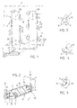
- Fig. 1 shows a proving chamber of which the chamber 1 has only been indicated with some dash lines.
- the conveying system 2 comprising two endless conveyors 3, which have been mounted one after the other in two vertical planes 4 running parallel (see also fig. 2).
- the conveyors 3 can be endless chains.
- the conveyors 3 run over return rollers 5A and 5B, which can be chain wheels. At the return rollers 5A the conveyors are led round over 180° and at the rollers 5B over 90°.
- the endless conveyors 3 have been provided with bearing pins 6.
- Each conveyor has a pair 7 of such bearing pins 6 per carrier.
- the bearing pins 6 of the two conveyors 3 run in line in pairs and are square to the planes 4.
- Two pairs 7 of such bearing pins 6 support one carrier 8, comprising a tube-shaped holder 9, which has been provided with a longitudinal opening 10 for bringing the pieces of dough 11 in and out of the holder.
- a carrier 8 For the purpose of receiving more than one piece of dough in a carrier 8, cross plates 12 can be mounted in the tube-shaped holder 9, while the holder 9 has been closed off at the ends by means of transverse walls 13. In the transverse walls 13 are slots 14 which cooperate with the bearing pins 6.
- the two slots 14 form such an angle with each other, that the carrier concerned can take up two stable positions on the pins 6.
- Fig. 5 shows a further possibility of both bearing pins 6 being displaceable in one single slot 14 in the transverse wall 13.
- a pushing mechanism 15 which can be activated at a certain moment.
- This pushing mechanism can be for example an air cilinder 16 provided with a piston rod 17 with a roller 18 thereto.
- the roller 18 can cooperate with a part of the transverse wall 13, so that the carrier 8 can suddenly be tilted from the one position to the other, as it will be described further.
- the carriers 8 will move upwards and take up the stable position, indicated with A, on the pins 6.
- the pins 6 will start to take up another position in relation to each other and the carrier 8 can for example take up the positon as indicated with B. This will depend on the friction that occurs between the pins 6 and the carrier 8 and on the position of the piece of dough 11 in the carrier. The piece of dough can stick to the wall of the carrier to a more or lesser degree.
- the carrier In the position B, indicated with dash lines, the carrier has not yet carried out a displacement in relation to the pins 6. However, a similar displacement can have taken place.
- the carrier 8 When the carrier 8 ends up at a lower return roller 5B, the carrier is rotated to the position such as illustrated at the left below in fig. 6 and indicated with F. In this position F, the carrier 8 still takes up a stable position in relation to the pins 6 and the piece of dough 11 will not yet be able to fall out of the carrier 8.
- the pushing mechanism 15 already described above can be activated by which the carrier 8 is suddenly tilted from the position F to the position as illustrated at the left in fig. 7 and has been indicated with G. At that moment, the piece of dough 11 falls out of the carrier to end up on a conveyor belt 19, which has been indicated in the figs. 1 and 6.
- the carrier 8 remains in the same position in relation to the pins 6 with moving of the conveyors 3 from the one return roller 5B to the other return roller 5B, as has been indicated in fig. 1.
- the carriers will take up approximately the same position as indicated in the figs. 6 and 7 when instead of the embodiment of the carriers according to fig. 3 the embodiments according to figs. 4 and 5 will be applied.
- the two conveyors 3 can be replaced by one single conveyor, which will then be provided with bearing pins 6 at both sides.
- the parts of the conveyors 3 running vertically in fig. 1 could also extend in horizontal direction.
- two cooperating pins 6 of a conveyor 3 will then also have to be in a vertical plane so that then the conveyors will have to be designed wider.
Landscapes
- Life Sciences & Earth Sciences (AREA)
- Engineering & Computer Science (AREA)
- Food Science & Technology (AREA)
- Manufacturing And Processing Devices For Dough (AREA)
- Structure Of Belt Conveyors (AREA)
Claims (6)
- Chambre de levage de pâte comportant une chambre (1) ayant à l'intérieur un dispositif de transport (2) constitué d'au moins un convoyeur sans fin (3) se déplaçant dans un plan (4) pratiquement vertical et étant guidé dans celui-ci par plusieurs rouleaux de renvoi (5a, 5b), au niveau duquel le convoyeur (3) sert à supporter plusieurs porteurs (8) constitués chacun d'un dispositif de retenue (9) ayant pratiquement la forme d'un tube dont l'axe central est à peu près horizontal et perpendiculaire au plan (4) du convoyeur (3), lequel dispositif de retenue (9) comporte une ouverture longitudinale (10) pour mettre un morceau de pâte (11), ou plusieurs morceaux de pâte situés l'un à côté de l'autre dans la direction longitudinale du dispositif de retenue, dans le porteur (8) ou pour enlever un morceau de pâte (11) à partir de celui-ci, lesquels porteurs (8) sont fermés au niveau des extrémités par des parois transversales (13), et des moyens (6, 7, 14) existant entre une paroi transversale (13) et un convoyeur (3) pour supporter les porteurs (8) par rapport au convoyeur (3), caractérisée en ce que les moyens (6, 7, 14) existant entre une paroi transversale (13) d'un porteur (8) et un convoyeur (3) sont conçus de telle sorte que la majeure partie de la distance sur laquelle le porteur est déplacé par l'intermédiaire du convoyeur (3), le porteur (8) prendra toujours une position stable dans laquelle l'ouverture (10) du porteur (8) est dirigée vers le haut en formant un certain angle (β) avec la verticale et le porteur (8) en basculant de la première position stable (A) vers l'autre (E) lorsque le convoyeur (3) passe sur un rouleau de renvoi (5a).
- Chambre de levage de pâte selon la revendication 1, caractérisée en ce qu'au niveau du dernier rouleau de renvoi (5b), là où existe un morceau de pâte (11) à décharger d'un porteur (8) se déplaçant vers le bas, des moyens (15) sont présents pour faire basculer de manière soudaine le porteur concerné (8), qui est déjà de manière possible mis quelque peu en rotation, depuis la première position stable (F) vers l'autre position stable (G) dans laquelle l'ouverture (10) du porteur (8) est dirigée vers le bas.
- Chambre de levage de pâte selon la revendication 1 ou 2, caractérisée en ce que les moyens (6, 7, 14) destinés à supporter un porteur (8) par rapport au convoyeur (3) sont formés d'une paire (7) de doigts porteurs (6), lesquels doigts porteurs (6) sont à une certaine distance l'un de l'autre et sont dirigés perpendiculairement au plan de déplacement (4) du convoyeur (3), dans lequel pendant le déplacement le long de trajets parallèles du convoyeur, les doigts porteurs (6) de chaque paire (7) sont dans un plan similaire pratiquement vertical et au moins un des doigts porteurs (6) coopère avec une fente (14) qui est agencée dans la paroi transversale (13) du porteur (8), ladite paroi étant à proximité des doigts porteurs (6).
- Chambre de levage de pâte selon la revendication 3, caractérisée en ce que le premier doigt (6) d'une paire (7) de doigts porteurs coopère avec une fente (14) constituée dans la paroi transversale (13) d'un porteur (8) et l'autre doigt porteur (6) de la paire (7) est relié de manière pivotante à la même paroi transversale (13).
- Chambre de levage de pâte selon la revendication 3, caractérisée en ce que le premier doigt (6) d'une paire de doigts porteurs coopère avec une fente (14) constituée dans la paroi transversale (13) d'un porteur (8) et l'autre doigt porteur (6) de la paire (7) coopère avec la même fente (14) ou avec une autre fente (14) située dans la paroi transversale (13) du porteur (8).
- Chambre de levage de pâte selon l'une quelconque des revendications précédentes, caractérisée en ce que le dispositif de transport comporte deux convoyeurs sans fin (3), qui se déplacent dans des plans (4) mutuellement parallèles, lesquels convoyeurs sont munis de doigts porteurs (6) se trouvant en ligne pour supporter de manière pivotante les porteurs (8) par rapport aux doigts porteurs et étant situés entre les convoyeurs.
Applications Claiming Priority (2)
| Application Number | Priority Date | Filing Date | Title |
|---|---|---|---|
| NL9002579 | 1990-11-27 | ||
| NL9002579A NL9002579A (nl) | 1990-11-27 | 1990-11-27 | Rijskast bestaande uit een eindloos transportsysteem en daarmee verbonden dragers. |
Publications (2)
| Publication Number | Publication Date |
|---|---|
| EP0488439A1 EP0488439A1 (fr) | 1992-06-03 |
| EP0488439B1 true EP0488439B1 (fr) | 1994-10-05 |
Family
ID=19858039
Family Applications (1)
| Application Number | Title | Priority Date | Filing Date |
|---|---|---|---|
| EP91202970A Expired - Lifetime EP0488439B1 (fr) | 1990-11-27 | 1991-11-15 | Appareil permettant à la pâte de lever, comportant un transporteur sans fin et support s'y rapportant |
Country Status (4)
| Country | Link |
|---|---|
| EP (1) | EP0488439B1 (fr) |
| AT (1) | ATE112453T1 (fr) |
| DE (1) | DE69104463T2 (fr) |
| NL (1) | NL9002579A (fr) |
Family Cites Families (2)
| Publication number | Priority date | Publication date | Assignee | Title |
|---|---|---|---|---|
| FR1557905A (fr) * | 1968-01-09 | 1969-02-21 | ||
| NL8700439A (nl) * | 1987-02-23 | 1988-09-16 | Johannes Antonius Josephus Lee | Kast voor het laten rijzen van deegstukken. |
-
1990
- 1990-11-27 NL NL9002579A patent/NL9002579A/nl not_active Application Discontinuation
-
1991
- 1991-11-15 AT AT91202970T patent/ATE112453T1/de not_active IP Right Cessation
- 1991-11-15 DE DE69104463T patent/DE69104463T2/de not_active Expired - Fee Related
- 1991-11-15 EP EP91202970A patent/EP0488439B1/fr not_active Expired - Lifetime
Also Published As
| Publication number | Publication date |
|---|---|
| NL9002579A (nl) | 1992-06-16 |
| EP0488439A1 (fr) | 1992-06-03 |
| ATE112453T1 (de) | 1994-10-15 |
| DE69104463T2 (de) | 1995-06-08 |
| DE69104463D1 (de) | 1994-11-10 |
Similar Documents
| Publication | Publication Date | Title |
|---|---|---|
| EP0480436A3 (en) | Distributing and collecting device for products to be conveyed | |
| EP0139775B1 (fr) | Dispositif pour le transport et l'accumulation d'objets | |
| US2268724A (en) | Transfer device for conveyers | |
| NL8000895A (nl) | Inrichting voor het uit een deegbaan produceren van een aantal trapezoidale stukken deeg met dezelfde gerichtheid. | |
| NL8901613A (nl) | Broodsnijmachine. | |
| US5197586A (en) | Automatic machine for uprightly positioning and feeding containers | |
| EP0559302A2 (fr) | Convoyeur | |
| US2715973A (en) | Depanning machines | |
| EP0037142A1 (fr) | Dispositif pour le calibrage de produits tels que fruits | |
| EP0488439A1 (fr) | Appareil permettant à la pâte de lever, comportant un transporteur sans fin et support s'y rapportant | |
| HU218806B (hu) | Görgős poggyászt döntő konvejor | |
| EP0078342B1 (fr) | Système pour transporter des articles coniques | |
| US4645062A (en) | Transfer apparatus for flat items | |
| EP0593126B1 (fr) | Convoyeur de tri à décharge magnétique | |
| GB1589981A (en) | Pouch shaping mechanism | |
| NL8600225A (nl) | Werkwijze en inrichting voor het verpakken van eieren of soortgelijke kwetsbare voorwerpen. | |
| DE59202789D1 (de) | Ausschleusvorrichtung. | |
| GB2049599A (en) | Apparatus for turning over conveyed articles | |
| US1979553A (en) | Apparatus fob cooling baker | |
| ES2265030T3 (es) | Dispositivo para el vaciado de los contenedores de frutas y productos vegetales. | |
| US3857477A (en) | Tray turnover device | |
| US2681727A (en) | Tray tilting and pan discharging device | |
| US4454942A (en) | System for conveying conical articles | |
| EP0648694B1 (fr) | Convoyeur | |
| JP2603146B2 (ja) | 氷の垂直搬送装置 |
Legal Events
| Date | Code | Title | Description |
|---|---|---|---|
| PUAI | Public reference made under article 153(3) epc to a published international application that has entered the european phase |
Free format text: ORIGINAL CODE: 0009012 |
|
| AK | Designated contracting states |
Kind code of ref document: A1 Designated state(s): AT BE DE FR IT NL SE |
|
| 17P | Request for examination filed |
Effective date: 19921006 |
|
| 17Q | First examination report despatched |
Effective date: 19931129 |
|
| GRAA | (expected) grant |
Free format text: ORIGINAL CODE: 0009210 |
|
| AK | Designated contracting states |
Kind code of ref document: B1 Designated state(s): AT BE DE FR IT NL SE |
|
| PG25 | Lapsed in a contracting state [announced via postgrant information from national office to epo] |
Ref country code: AT Effective date: 19941005 Ref country code: BE Effective date: 19941005 Ref country code: IT Free format text: LAPSE BECAUSE OF FAILURE TO SUBMIT A TRANSLATION OF THE DESCRIPTION OR TO PAY THE FEE WITHIN THE PRE;WARNING: LAPSES OF ITALIAN PATENTS WITH EFFECTIVE DATE BEFORE 2007 MAY HAVE OCCURRED AT ANY TIME BEFORE 2007. THE CORRECT EFFECTIVE DATE MAY BE DIFFERENT FROM THE ONE RECORDED.SCRIBED TIME-LIMIT Effective date: 19941005 |
|
| REF | Corresponds to: |
Ref document number: 112453 Country of ref document: AT Date of ref document: 19941015 Kind code of ref document: T |
|
| REF | Corresponds to: |
Ref document number: 69104463 Country of ref document: DE Date of ref document: 19941110 |
|
| PG25 | Lapsed in a contracting state [announced via postgrant information from national office to epo] |
Ref country code: SE Effective date: 19950105 |
|
| ET | Fr: translation filed | ||
| PLBE | No opposition filed within time limit |
Free format text: ORIGINAL CODE: 0009261 |
|
| STAA | Information on the status of an ep patent application or granted ep patent |
Free format text: STATUS: NO OPPOSITION FILED WITHIN TIME LIMIT |
|
| 26N | No opposition filed | ||
| PGFP | Annual fee paid to national office [announced via postgrant information from national office to epo] |
Ref country code: NL Payment date: 19951128 Year of fee payment: 5 |
|
| PGFP | Annual fee paid to national office [announced via postgrant information from national office to epo] |
Ref country code: FR Payment date: 19951130 Year of fee payment: 5 |
|
| PGFP | Annual fee paid to national office [announced via postgrant information from national office to epo] |
Ref country code: DE Payment date: 19960124 Year of fee payment: 5 |
|
| PG25 | Lapsed in a contracting state [announced via postgrant information from national office to epo] |
Ref country code: NL Effective date: 19970601 |
|
| PG25 | Lapsed in a contracting state [announced via postgrant information from national office to epo] |
Ref country code: FR Effective date: 19970731 |
|
| NLV4 | Nl: lapsed or anulled due to non-payment of the annual fee |
Effective date: 19970601 |
|
| PG25 | Lapsed in a contracting state [announced via postgrant information from national office to epo] |
Ref country code: DE Effective date: 19970801 |
|
| REG | Reference to a national code |
Ref country code: FR Ref legal event code: ST |