EP0488499A2 - Appareil de transport de cassettes de film à rayons-X - Google Patents
Appareil de transport de cassettes de film à rayons-X Download PDFInfo
- Publication number
- EP0488499A2 EP0488499A2 EP91307562A EP91307562A EP0488499A2 EP 0488499 A2 EP0488499 A2 EP 0488499A2 EP 91307562 A EP91307562 A EP 91307562A EP 91307562 A EP91307562 A EP 91307562A EP 0488499 A2 EP0488499 A2 EP 0488499A2
- Authority
- EP
- European Patent Office
- Prior art keywords
- cassette
- gripper assembly
- controller
- path
- home position
- Prior art date
- Legal status (The legal status is an assumption and is not a legal conclusion. Google has not performed a legal analysis and makes no representation as to the accuracy of the status listed.)
- Granted
Links
- 230000004044 response Effects 0.000 claims abstract description 7
- 230000003068 static effect Effects 0.000 claims description 3
- 239000002344 surface layer Substances 0.000 claims description 2
- XLYOFNOQVPJJNP-UHFFFAOYSA-N water Substances O XLYOFNOQVPJJNP-UHFFFAOYSA-N 0.000 claims 1
- 239000010410 layer Substances 0.000 description 6
- 238000003384 imaging method Methods 0.000 description 4
- 239000000463 material Substances 0.000 description 4
- 230000000694 effects Effects 0.000 description 3
- 238000003780 insertion Methods 0.000 description 3
- 230000037431 insertion Effects 0.000 description 3
- 229920003023 plastic Polymers 0.000 description 3
- 230000006870 function Effects 0.000 description 2
- 239000011159 matrix material Substances 0.000 description 2
- 229920006311 Urethane elastomer Polymers 0.000 description 1
- XAGFODPZIPBFFR-UHFFFAOYSA-N aluminium Chemical compound [Al] XAGFODPZIPBFFR-UHFFFAOYSA-N 0.000 description 1
- 229910052782 aluminium Inorganic materials 0.000 description 1
- 239000000872 buffer Substances 0.000 description 1
- 230000006835 compression Effects 0.000 description 1
- 238000007906 compression Methods 0.000 description 1
- 230000003750 conditioning effect Effects 0.000 description 1
- 230000002596 correlated effect Effects 0.000 description 1
- 230000000875 corresponding effect Effects 0.000 description 1
- 229920002457 flexible plastic Polymers 0.000 description 1
- 239000002783 friction material Substances 0.000 description 1
- 230000003287 optical effect Effects 0.000 description 1
- 230000005855 radiation Effects 0.000 description 1
- 230000001629 suppression Effects 0.000 description 1
Images





Classifications
-
- G—PHYSICS
- G03—PHOTOGRAPHY; CINEMATOGRAPHY; ANALOGOUS TECHNIQUES USING WAVES OTHER THAN OPTICAL WAVES; ELECTROGRAPHY; HOLOGRAPHY
- G03B—APPARATUS OR ARRANGEMENTS FOR TAKING PHOTOGRAPHS OR FOR PROJECTING OR VIEWING THEM; APPARATUS OR ARRANGEMENTS EMPLOYING ANALOGOUS TECHNIQUES USING WAVES OTHER THAN OPTICAL WAVES; ACCESSORIES THEREFOR
- G03B42/00—Obtaining records using waves other than optical waves; Visualisation of such records by using optical means
- G03B42/02—Obtaining records using waves other than optical waves; Visualisation of such records by using optical means using X-rays
- G03B42/025—Positioning or masking the X-ray film cartridge in the radiographic apparatus
Definitions
- This invention relates to a trayless film cassette transport apparatus which includes an improved cassette gripping system.
- cassettes which serve to support and mechanically protect the film as well as to shield it from ambient light.
- cassettes are generally square or rectangular in shape and come in a variety of sizes.
- the cassette After being loaded with a sheet of unexposed film, the cassette itself must be loaded into the x-ray imaging machine and centered at a desired location prior to being exposed to radiation which has been directed through a portion of the body of a person or some other object to be imaged. Following exposure, the cassette must be removed from the imaging machine so that the exposed film can be removed from the cassette and developed.
- cassette handling systems for facilitating these operations.
- the entire carriage, including the gripper, is then translated to move the cassette to an exposure position. Following exposure, the carriage is translated in the opposite direction to position the cassette in alignment with the window. To eject the cassette, the gripper is then moved toward its home position where it both stops and releases the cassette.
- the means by which it does so can be better understood with particular reference to Fig. 4 of US 3829733 as described below.
- the gripper assembly (40) of US 3829733 includes a cassette supporting plate (42) which carries a bearing block (48) upon which a spring-loaded upper jaw (52) is pivotably mounted.
- the upper jaw (52) is linked to an opposed lower jaw (64) mounted on the other side of plate (42).
- the lower jaw carries a roller which moves either upward through an opening in plate (42) to engage a detent on the cassette or downward through the opening to release a cassette.
- a spring (70) normally biases jaws (52) and (64) together to grip a cassette with a force that is limited by the strength of spring (72).
- a cam follower (73) that is connected to the lower jaw (64) by means of a follower (74) engages a cam ramp (76). This engagement overcomes spring (72) and opens jaws (52) and (64) so that they release the cassette.
- a drawback of the above design is that the gripper cannot release the cassette until the gripper is positioned at its home position which lies a fixed distance from the window. If the home position is so located with respect to the window that a readily graspable portion of a small cassette projects unsupported from the window when the small cassette is ejected, an even larger portion of a large cassette will lie unsupported when that large cassette is ejected. This can result in the large cassette being precariously balanced upon ejection.
- An x-ray film cassette transport apparatus in accordance with the invention comprises a gripper assembly movable within a housing between a home position adjacent a window formed in the housing through which the cassette may be transferred and a retracted position, and means to cause the gripper assembly to grip the cassette while the gripper assembly is driven from the home position to the retracted position and to cause the gripper assembly to release the cassette whilst the gripper assembly is driven from the retracted position to the home position, characterised in that the gripper assembly releases the cassette before the gripper assembly reaches the home position.
- a controller is provided to arrest the drive of the gripper assembly at an ejection position intermediate the retracted position and the home position and the home position, and after the gripper assembly has released the cassette.
- the controller includes means for determining the location of the ejection position along the path of movement of the gripper assembly as a function of the length of the cassette in the direction of the path.
- a trayless film cassette transport apparatus having a cassette gripping system which allows a cassette to be loaded through a window; then gripped and withdrawn inwardly to an exposure position; then ejected to project partially from the window by a distance which is automatically determined according to the size of the cassette. This ensures that small cassettes project far enough from the window to be readily grasped by an operator while avoiding ejecting large cassettes so far that they are precariously balanced in the window.
- the apparatus preferably comprises a pair of guides, each engageable with a side portion of the cassette and driveably mounted within the housing so as to move towards and away from one another in a direction substantially perpendicular to the path of motion of the gripper assembly, characterised in that throughout the range of movement of the guides each guide is located the same distance from the path.
- a pair of guides each engageable with a side portion of the cassette and driveably mounted within the housing so as to move towards and away from one another in a direction substantially perpendicular to the path of motion of the gripper assembly, characterised in that throughout the range of movement of the guides each guide is located the same distance from the path.
- the gripper assembly is mounted for reciprocal movement along a track between a home position located adjacent the window and a retracted position spaced farther away from the window.
- the gripper assembly also includes a cam follower which, as the gripper assembly travels along the track, moves along a cam surface which, may take the form of a slot formed in the track.
- the cam surface includes first and second portions which lie offset from one another.
- a mechanical linkage connects the cam follower to a jaw, or cassette-engaging member, which moves between positions to grip the cassette and to release the cassette as the cam follower moves in the direction of the offset as a result of the gripper assembly being driven back and forth along the length of the track.
- the initial portion of the cassette-loading movement causes the cam follower to move in the direction of the offset between the first and second portions of the cam surface.
- a mechanical linkage causes the jaw to grip the cassette throughout most of the movement of the gripper assembly to its final retracted position.
- the apparatus preferably also comprises a cassette position sensing means to sense the movement of a part of the cassette past a particular position and to generate a signal which is utilized by the controller in order to determine the size of the cassette. Based on that information, the controller calculates the appropriate retracted position whereat the gripper assembly is stopped to properly locate a cassette of that particular size along the path along which it is moved by the gripper assembly.
- the gripper assembly From the retracted position, following exposure of the film inside the cassette, the gripper assembly commences a cassette-ejecting movement back toward the home position. As the cassette-ejecting movement of the gripper proceeds, the cam follower engages the other portion of the cam surface causing the cam follower to move in the opposite sense along the direction of the offset. The linkage simultaneously moves the jaw or cassette-engaging member to release the cassette before the gripper assembly reaches its home position. The controller then stops the movement of the gripper assembly at an ejection position whose distance from the home position is determined by the size of the cassette. The gripper remains at the ejection position until the cassette is manually withdrawn clear of the apparatus whereupon the gripper assembly moves back to the home position to await loading of the next cassette.
- the cassette-engaging member or jaw, has a substantially planar cassette gripping surface layer subtending an angle ⁇ with the inclined path and having a coefficient of static friction ⁇ s with respect to the cassette, characterised in that ⁇ and ⁇ s substantially obey the equation: TAN ⁇ ⁇ ⁇ s
- the cassette is engaged under a self-locing condition such that the gripping force on the cassette increases in response to and at a greater rate than an improperly imposed cassette-withdrawal force.
- an X-ray film cassette transport apparatus 15 in accordance with invention includes a generally rectangular housing 16 which preferably forms part of a Bucky having an oscillatable anti-scatter grid (not shown). Hising 16 has a front wall 17 in which is formed a window 18 which takes the form of a rectangular slot through which a cassette 20 of a range of sizes may be passed.
- an inclined loading ramp 22 extends outwardly in the -y direction and slightly downwardly from front wall 17 at a location beneath window 18.
- An eject pushbutton 23 is mounted flushly on loading ramp 22 as is a cassette-present light 24 which is lighted to indicate whenever a cassette is present inside apparatus 15.
- Pushbutton 23 and light 24 each communicate directly or indirectly by way of suitable signal conditioning circuits (not shown) to a microprocessor-based controller 30 which wil be described in further detail below.
- an entry sensor comprising an infra-red LED transmitter 27 disposed bove window 18 and a receiver 29 located beneath window 18.
- Transmitter 27 projects an infra-red beam 28 downwardly across window 18 to a receiver 29 which generates and transmits to controller 30 a signal indicating whether or not a portion of a cassette 20 obstructs a predetermined entry position 29a which lies at a point fixed along axis 50.
- Controller 30 is housed in a shielded compartment 31 inside housing 16. Also located inside compartment 31 are an optional Bucky gird driver 33 and a power supply 34. Controller 30 and grid driver 33 are each supplied operating power from power supply 34 by way of appropriate electrical connections 35 and 36. Controller 30 is also connected to optional grid driver 33 by way of other wiring connections 38 through which signals effective to initiate driving and stopping of the anti-scatter grid are transmitted. Electrical connections between eject pushbutton 23 and light 24 on one hand and controller 30 on the other are made at least in part by way of a large printed circuit board 40 whose non-conductive side occupies most of the base portion of housing 16 lying outside compartment 31.
- Apparatus 15 includes a pair of guides 45 and 46 which reciprocate toward and away from one another along respective tracks 47 and 48 while always maintaining the same distance from a central path 50.
- controller 30 which is operably connected to a guide motor 52 which may suitably be of the inexpensive D.C. brush type.
- motor 52 may be connected to a suitable radio frequency interference suppression network such as a common mode filter (not shown).
- a suitable radio frequency interference suppression network such as a common mode filter (not shown).
- the electrical connections between motor 52 and controller 30 may be made by way of a separate shielded cable rather than by way of printed circuit board 40.
- Motor 52 is connected to a toothed guide drive sprocket 55 around which is reaved a flexible plastic guide drive chain 56.
- Chain 56 is further reaved around additional sprockets 57, 58 and 59 to define a continuous, substantially L-shaped path as shown.
- the lower leg of that path comprises an inner portion 61 and an outer portion 62 which run parallel to one another in a direction substantially perpendicular to path 50.
- the inner portion 61 of chain 56 is connected to the right-hand guide 46 at a point 63 while the outer portion 62 of chain 56 is connected to the left-hand guide 45.
- guides 45 and 46 are positioned at their fully retracted home positions as illustrated in Fig. 1, a guide home limit switch 66 (shown in Fig.
- guides 45 and 46 When motor 52 drives sprocket 55 counter-clockwise, guides 45 and 46 will travel at even rates toward axis 50 and that upon reversal of motor 52, guides 45 and 46 will travel back toward their respective home positions at similarly even rates. At least one of guides 45 and 46 has mounted thereon a sensor such as limit switches 70 and 71 for generating and transmitting to controller 30 a signal indicating engagement of guides 45 and 46 with the respective side portions S1 and S2 of cassette 20.
- a sensor such as limit switches 70 and 71 for generating and transmitting to controller 30 a signal indicating engagement of guides 45 and 46 with the respective side portions S1 and S2 of cassette 20.
- apparatus 15 includes an elongated track 80 whose longitudinal axis lies parallel to and preferably coincides with central path 50.
- Track 80 is conveniently formed from a rectangular sheet of plastic or other suitable material into which has been milled or otherwise formed a straight guide slot 82 and a cam slot 83 (shown in Fig. 2).
- Cam slot 83 includes a straight upper segment 85 and a looped lower segment 86.
- Cam slot 83 defines a cam surface having a first portion 88 and a second portion 89.
- the left side wall of the righthand side (+x direction) side of segment 86 defines first portion 88 while second portion 89 is defined by the straight left side wall which is in common with both the straight upper segment 85 and the leftmost (-x direction) side of the looped lower segment 86 of cam slot 83.
- the cam surface need not be a continuous surface and the operation of portions 88 and 89 thereof can be achieved equivalently by separate cams.
- the upper and lower segments 85 and 86 of the cam surface are bridged by a leaf spring 91 forming a one-way gate, one end of which permanenetly adjoins the first portion 88 of the cam surface and whose other end is biased into contact with the second portion 89 thereof as illustrated in Fig. 1.
- a leaf spring 92 forming a second one-way gate which extends from the rightmost side wall of segment 86 and is biased twoard the opposing side wall to assume the position illustrated in Fig. 3.
- a gripper assembly 100 which is slidably mounted upon track 80 for movement between at least a home position 102 which lies relatively close to window 18 and a maximum retracted position 103 which lies farther away from window 18 as measured along path 50 in the +y direction.
- a gripper home sensor which may conveniently take the form of a limit switch 106 which is disposed in fixed relation to home position 102 for generating and transmitting to controller 30 a signal indicating when gripper assembly 100 is present at home position 102.
- Sensing element 108 may be a retroreflective type and is capable of generating and transmitting to controller 30 a signal indicating the presence of a cassette in grippable proximity to the gripper assembly 100 when blocked by a movable actuator such as a flag plate 114 attached to a mechanical member 110.
- Member 110 is pivotably mounted to the body 101 of gripper assembly 100 at a point 111 (best seen in Fig. 7) and includes a cassette-contracting surface 113 which lies in a plane disposed for contact with the leading edge L of a cassette 20.
- Flag plate 114 is connected at a right angle to cassette-contacting surface 113 and is capable of pivoting into an active position lying in front of sensing element 108 when gripper assembly 100 is positioned at its home position 102 and when the leading edge L of a cassette 20 is pressed against cassette-contacting surface 113.
- sensing element 108 Upon concurrence of those two events, sensing element 108 generates and transmits to controller 30 the aforementioned signal indicating the presence of a cassette 20 in grippable proximity to gripper assembly 100.
- a pair of weak springs 115 and 116 lie under slight compression between the rear of the cassette-contacting surface 113 of member 110 and the body 101 of the gripper assembly 100. Those springs serve to normally bias flag plate 114 into an inactive position as shown in Fig. 7. When springs 115 and 116 are overcome by the leading edge L of a cassette 20 in forceable engagement with surface 113, actuating member 114 moves to an active position as indicated by the arrow in Fig. 7.
- Gripper assembly 100 is driven bi-directionally along track 80 by means of a gripper motor 120 which reversably drives a gripper drive sprocket 122.
- a gripper motor 120 Aligned with sprocket 122 along an axis lying parallel to path 50, printed circuit board 40 supports a passive sprocket 124.
- a continuous flexible, plastic gripper drive chain 125 Around sprockets 122 and 124 and there is reaved a continuous flexible, plastic gripper drive chain 125 in the form of an elongated loop running generally parallel to path 50.
- the leg of drive chain 125 lying adjacent gripper assembly 100 is secured to body 101 by means of a suitable fastener 126.
- Gripper motor 120 is driveably coupled to an optically isolated rotary encoder 127 which, whenever motor 120 is driven, generates and transmits to controller 30 pulse signals whose spacing is correlated to the distance travelled by gripper assembly 100 along path 50.
- encoder 127 may provide 18 pulses per complete revolution of motor 120 and where the effective gear ratio is 50 to 1, one revolution of gripper motor 120 moves gripper assembly 100 along path 50 a distance of about 0.059 inches (1.5mm) which corresponds to about 305.084 pulses per inch (12.011 pulses per mm).
- gripper assembly 100 is so contracted as to effect a self-locking condition when it grips cassette 20. Under this self-locking condition, the cassette is ordinarily gripped securely but under elatively low force. However, if a withdrawal force is applied to cassette 20 in the -y direction when it is engaged by gripper assembly 100, the gripping force exerted by gripper assembly 100 will increase in response to and at a greater rate than the withdrawal force.
- the underside of body 101 includes at least one and preferably two projections 99 on either side thereof.
- the body 101 may conveniently be formed of a rigid plastic or other suitable rigid material.
- Body 101 includes a planar lower shelf 129 which serves to support a portion of the bottom of a cassette 20 and provides a reaction force when the cassette is gripped by gripper assembly 100.
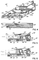
- a movable cassette engaging member which may take the form of a jaw 131.
- Jaw 131 may be formed from a plate of aluminum or other rigid, x-ray tranparent material having affixed to its underside a layer 132 of high-friction material having a coefficient of static friction ⁇ s with respect to cassette 20 which is as high as practicable.
- Layer 132 may comprise a 0.065 inch (1.65 mm) thick layer of urethane rubber having a durometer of 50A ⁇ 5.
- other suitable materials may be used.
- Jaw 131 is rigidly secured by means of screws 134 (shown in Fig. 1) or other suitable means to an elevator 135 which is slidable between a lowered first position, (whereat jaw 131 assumes a cassette-engaging position with layer 132 in planar contact with the top of cassette 20, as shown in Fig. 5) and an elevated second position as illustrated in Fig. 6 (whereat jaw 131 including layer 132 are moved upward to a cassette-disengaging position as shown in Fig. 6). Elevator 135 moves between the first and second positions along an inclined path defined by a low friction elevator track 137 which is disposed partially along opposed walls of a recess formed in body 101 and partially along opposite sides of elevator 135.
- Elevator track 137 defines an angle with respect to the lower surface of layer 132 and lower shelf 129 so that thoughout its travel, jaw 131 remains parallel to the upper surface of shelf 129 in order to permit the selective clamping and releasing of a cassette 20 as elevator 135 moves jaw 131 between its cassette-engaging and cassette-disengaging positions as shown in Figs. 5 and 6, respectively.
- ⁇ is suitably about twenty degrees.
- elevator 135 is freely movable with a minimum of friction along the path defined by track 137, and has an absolute minimum of play in other directions.
- ⁇ and ⁇ s are selected such that they obey the equation: TAN ⁇ ⁇ ⁇ s
- the combined bias force exerted by springs 138a and 138b is selected to be great enough to permit jaw 131 to grip cassette 20 securely when jaw 131 is in its cassette-engaging position, but small enough that the bias force can be overcome by the force transmitted to the elevator 135 in the opposing direction by the lever which will now be described.
- a lever 141 is pivotably mounted to the underside of body 101 at a pivot point 143 as illustrated in Fig. 4.
- a cam follower 145 extends downwardly from one end of lever 141 and is free to travel back and forth along an arcuate slot 147 formed in the underside of body 101.
- the other end of lever 141 includes an upward projection 148 which engages a recess 149 located in the underside of elevator 135.
- Springs 138a and 138b transmitted through elevator 135 act to forceably bias lever 141 to the leftward position as shown in Fig. 4 (i.e., in the -x direction in Fig. 1).
- cam follower 145 engages the second portion 89 of the cam surface defined by track 80 where it remains as gripper assembly 100 is retracted in the +y direction past the leaf spring 91. Thereafter, when the gripper assembly 100 is driven forward to window 18, cam follower 145 will engage the opposite side of leaf spring 91 which will prevent it from returning along the path taken during its retraction. Instead, as gripper assembly 100 is moved back toward window 18, leaf spring 91 forces cam follower 145 to move in the +x direction so that it then engages the first portion 88 of the cam surface. As it does so, projection 148 moves with a component in the +x direction. This casues elevator 135 to move upwardly and in the +y direction along elevator track 137 to its first position thus moving jaw 131 to its cassette-disengaging position as illustrated in Fig. 6.
- controller 30 which comprises a conventionally configured microprocessor such as the Motorola MC6HC811 which includes memory for storing a software program and has an array of I/O ports. Separate ones of the I/O ports are connected by way of suitable buffers and/or optical isolators to entry sensor 26, guide home limit switch 66, eject pushbutton 23, cassette present sensing element 108, cassette present light 24, gripper home limit switch 106, as well as to encoder 127, a "grid home” sensor (not shown) and grid driver 33. Others are connected to a motor driver such as a conventionally configured Motorola part number MPM3002. The outputs of the motor driver comprise two lines which are capable of supplying a D.C.
- a motor driver such as a conventionally configured Motorola part number MPM3002.
- the outputs of the motor driver comprise two lines which are capable of supplying a D.C.
- the output of the motor driver is selectively switched to either the guide motor 52 or the gripper motor 120 by means of a relay, whose operating coil is controlled by a motor select output of the microprocessor.
- controller 30 Having described the structure of controller 30 and its connections to the various electrical components of apparatus 15, the operation of apparatus 15 will now be described with reference to the stored software program executed by controller 30. This description will be carried out with reference to the simplified flowcharts of Figs. 8 through 12 inclusive.
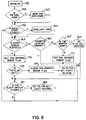
- controller 30 governs the movements of guides 45 and 46 as well as gripper assembly 100 in accordance with a stored software program having a main loop which will now be described with reference to Fig. 8.
- all I/O ports and registers are initialized at 152.
- the microprocessor interrogates the status of the "grid home" sensor to determine whether the anti-scatter grid is in its home position. If not, controller 30 executes, at 157, a routine to send the grid home by transmitting appropriate commands via electrical connections 38 effective to cause grid driver 33 to move the grid to its home position. Thereafter, controller 30 awaits closure of a Bucky start switch (not shown) which causes an optically isolated start signal 158 to be generated and transmitted to the microprocessor.
- a Bucky start switch not shown
- an oscillate grid routine 160 is executed. If the Bucky start switch is not closed or upon completion of the oscillate grid routine 160, the status of entry sensor 26 is checked at 163. If the infra-red beam 28 is blocked by a cassette 20, a check is made at 165 of the register whose status controls the cassette-present light 24. If a cassette 20 is already present inside apparatus 15, program flow skips to 181 where the status of eject switch 23 is checked. If the eject switch has not been closed, flow simply returns to block 159. If the eject switch has been closed, controller 30 executes an ACL EJECT routine (which will be described below with reference to Fig. 10) before returning to block 159.
- the status of the gripper home limit switch 106 is checked to determine whether the gripper is present at its home location 102. If so, an ACL routine 169 (which will be described in further detail with reference to Figs. 9A, 9B and 9C) is executed, whereupon flow proceeds to block 181. If no cassette is already present within apparatus 15 but check 167 reveals that gripper assembly 100 is not at home position 102, thee may have been an interruption of the power to controller 30 in the midst of a previous operating cycle. To account for this condition, the microprocessor sets a software "gripper error" flag at 171 and flow proceeds to block 181.
- the gripper error flag is fetched at 174 and its status checked at block 175. If the gripper error flag is not set, no previous power interruption has occurred and flow proceeds to block 181. Otherwise, the gripper error flag is cleared at 177 and the ACL EJECT routine is entered from 179.
- program flow is redirected to block 159.
- the status of eject switch 23 is checked and if closed, the ACL EJECT routine entered from block 182. If eject switch 23 is not closed, flow is redirected immediately to block 159 without first executing the ACL EJECT routine. Controller 30 continuously runs through the main loop as described so long as power is applied to apparatus 15.
- the status of the signal transmitted to controller 30 from the "guide home" limit switch 66 is checked to determine whether the guides are in their home position as shown in Fig. 1. If not, flow proceeds to the ACL eject routine at 192 and then back to the main loop at 192. If guides 45 and 46 are in their home positions, the positions of the various movable elements of apparatus 15 will be substantially as illustrated in Fig. 1 at the outset of operation.
- entry sensor 26 Upon insertion of a cassette 20, entry sensor 26 will send a signal to controller 30 indicating that a cassette 20 blocks entry position 29a. Further insertion of the cassette 20 into window 18 in the +y direction will cause its leading edge to abut the cassette-contacting surface 113 of member 110.
- the guide motor 52 is reversed at block 207 causing the guides to move slightly back toward their home positions until the sites S1 and S2 of the cassette are in a somewhat looser desired proximity of guides 45 and 46 as determined at 208 by again checking the status of switches 70 and 71. The desired proximity is reached when switches 70 and 71 both open. This serves to ensure that guides 45 and 46 do not unduly bind cassette 20 so as to interfere with its being moved by gripper assembly 100. Due to the fact that guides 45 and 46 move equidistantly with respect to axis 50, their inward movement serves to mechanically centre cassette 20 about path 50 such that equal portions of the cassette 20 as measured in the x direction lie on either side of path 50.
- the status of sensing element 108 is again checked at 211 to determine whether the leading edge L of cassette 20 has moved flag plate 114 to its active position. If not, the status of entry sensor 26 is checked at 213 to determine whether the cassette 20 has been withdrawn out of window 18 past entry point 29a. If not, the program loops repeatedly back to block 211 until sensing element 108 indicates that a cassette 20 is in grippable relation to the gripper assembly 100. If the check at 213 reveals that the entry sensor 26 has been cleared, the eject routine (which will be described in further detail with reference to Fig. 10) is entered at 216 and flow returns to the main loop at 217.
- controller 30 energizes gripper motor 120 to commence a cassette-loading movement.
- the cassette-loading movement includes two distinct phases.
- the first phase of this movement is a latching movement which is carried out by commanding gripper motor 120 to move gripper assembly 100 forward from its initial home position 102 by a short predetermined distance sufficient to permit the cam follower 145 to move past the second portion 89 of the cam surface. This is most clearly illustrated in Fig. 3 to which reference is now made.
- cam follower 145 When gripper assembly 100 is stopped at home position (Fig. 1), cam follower 145 is located approximately at position 219 shown in Fig. 3. Motor 120 is subsequently energised to move gripper assembly 100 initially a short predetermined distance in the -y direction toward window 18. When gripper assembly 100 is advanced by that predetermined distance, cam follower 145 clears the first portion 88 of the cam surface. The action of springs 138a and 138b then urge elevaotr 135 to its lowered position. As this occurs, cam follower 145 is displaced in the -x direction until it engages the second portion 89 of the cam surface, thus assuming the latched position 221 shown in Fig. 3.
- the second and predominant phase of the cassette-loading movement commences.
- gripper motor 120 is reversed causing gripper assembly 100 to move in the +y direction withdrawing cassette 20 further inside housing 16.
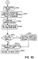
- controller 30 increments an "encode count" register in accordance with pulses received from encoder 127. As it does so, it continually checks at block 224 for the trailing edge of the cassette 20 to clear entry sensor 26.
- controller 30 throughout the remainder of the cassette-loading movement compares the instantaneous encoder count with a stored "max count" value corresponding to the maximum retracted position indicated at 103 in Fig. 1. So long as the present encoder count is lower than the max count value, the maximum travel of the gripper assembly 100 has not yet been reached and the movement of the gripper assembly 100 in the +y direction continues until the entry sensor 26 is cleared by the trailing edge of the cassette as determined at block 224. When entry sensor 26 is cleared, the current encoder count is saved and is later used to make a calculation at block 232 of Fig. 9C.
- controller 30 must compute how much farther the cassette must be withdrawn in order to centre it according to its size such that the central axis of the cassette as measured in the x direction is positioned at a desired centre along path 50. To do so, the controller 30 at 232 computes a "centre count” by subtracting the present encoder count from the stored max count value and dividing the result by two. The resulting "centre count” defines the number of additional encoder pulses by which the gripper assembly 100 must be further withdrawn in the +y direction in order to achieve the desired centering.
- gripper motor 120 is deenergized as indicated at block 236 to stop gripper assembly 100 at a desired retracted position as illustrated in Fig. 2.
- controller 30 uses a routine called SIZE, which is set forth in Appendix I, controller 30 then calculates the size of cassette 20 as measured along path 50. It then executes a test at block 240 to determine whether the cassette 20 is so small that the centred position at which it was stopped along track 80 at block 236 is not yet past the +y position of the one-way gate formed by leaf spring 91. If the cassette 20 was stopped at block 236 on the -y side of leaf spring 91, controller 30 at block 241 causes motor 120 to drive the gripper assembly 100 further in the +y direction past leaf spring 91 and then return it an equal distance in the -y direction. At 243 the controller 30 then loads a register effective to turn on the "cassette present" light 24 in order to indicate to an operator that a cassette 20 is loaded within apparatus 20 is now properly centred inside apparatus 15, whereupon an exposure can then be taken.
- SIZE a routine set forth in Appendix I
- Fig. 10 illustrates the ACL EJECT routine which commences in response to the pressing of eject pushbutton 23 or the receipt by controller 30 of an eject signal generated by the x-ray machine.
- cassette present light 24 is first turned off.
- the status of gripper home limit switch 106 is interrogated to determine whether the gripper assembly 100 is in its home position 102. If not, the RUN THE GRIPPER HOME routine is entered at 253.
- a check is made at 256 to determine once more if the gripper assembly 100 is at its home position 102. If not, the program returns to the main loop.
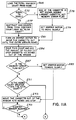
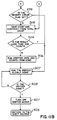
- the RUN THE GRIPPER HOME routine which will now be described with reference to Figs. 11A and 11B, operates to carry out a cassette-ejecting movement in which the gripper assembly 100 is moved back toward window 18 and then stopped so as to present a portion of cassette 20 extending outside window 18 so that an operator can readily grasp and remove the cassette. If the cassette 20 is small enough, gripper assembly 100 can be run completely to the home position before stopping. On the other hand, if the cassette 20 is a large one, as measured along the y axis, driving the gripper assembly 100 all the way to its home position 102 before stopping it could result in the cassette 20 being precariously balanced or even falling out of window 18. Accordingly, the RUN THE GRIPPER HOME routine determines the stopping, or ejection, point of the gripper assembly 100 based on the size of the cassette 20.
- controller 30 fetches the total encoder count accumulated since the gripper assembly 100 was last at its home position.
- controller 30 determines whether that count is equal to zero. If so, there has been an intervening power interruption and the size of the cassette 20 within apparatus 15 is not known by controller 30. In that event, as a safety measure, a "memory error" flag is set at bock 275 and subsequently, in block 279 the gripper motor 120 is set to move slowly and program flow proceeds to block 281 which will be described shortly.
- a "slow count” is computed by subtracting a predetermined number of counts from the total encoder count.
- the "slow count” represents the last portion of travel along path 50 along which it is desired to advance the gripper assembly 100 slowly rather than advance it at its normal rapid rate.
- the gripper motor 120 is energised to drive the gripper assembly 100 in the -y direction until entry sensor 106 is blocked by the trailing edge of cassette 20.
- the encoder count at the time entry sensor 26 was blocked is saved and added to an appropriate amount of pulses effective to stop the cassette at an ejection point such that less than about half and preferably only about 4.75 inches (114 mm) of the cassette 20 as measured along path 50 extends unsupported outside window 18.
- entry sensor 26 is repeatedly interrogated. Once the sensor 26 is no longer blocked, indicating that the operator has removed the cassette 20, the memory error flag is checked at 299. If the memory error flag has been set, flow advances to block 307 to be described below. Otherwise, flow proceeds to block 302 where the present encoder count at the time the entry sensor is blocked at 295 is saved and subtracted from the total encoder count. If the result is not less than a predetermined distance, such as 512 counts, gripper motor 120 is energised to run the gripper assembly 100 rapidly toward its home position until it is two hundred (200) counts away.
- a predetermined distance such as 512 counts
- the gripper assembly 100 By moving the gripper assembly 100 slowly during the final portion of its travel home, the possibility of the gripper overrunning home position 102 is avoided.
- gripper motor 120 is deenergised at block 401 and, at block 403 flow returns to the eject routine previously described with reference to Fig. 10.
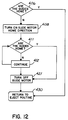
- the RUN THE GUIDES HOME routine commences with a check of the status of guide home limit switch 66 to determine whether the guides 45 and 46 are at their home position as illustrated in Fig. 1. If so, flow skips ahead to block 430 which returns to the ACL EJECT routine. If the guides 45 and 46 are not home, guide motor 52 is energized at block 408 in a sense appropriate to drive sprocket 55 clockwise, thereby moving guides 45 and 46 toward their home positions as shown in Fig. 1. In blocks 411 and 412, the driving of the guides 45 and 46 toward their home positions continues until the guide home limit switch 66 indicates that the guides are home. Then the guide motor 52 is turned off and flow is redirected at block 430 to the eject routine.
Landscapes
- Physics & Mathematics (AREA)
- General Physics & Mathematics (AREA)
- Sheets, Magazines, And Separation Thereof (AREA)
- Radiography Using Non-Light Waves (AREA)
Applications Claiming Priority (2)
| Application Number | Priority Date | Filing Date | Title |
|---|---|---|---|
| US07/618,057 US5062130A (en) | 1990-11-26 | 1990-11-26 | X-ray film cassette transport |
| US618057 | 1990-11-26 |
Publications (3)
| Publication Number | Publication Date |
|---|---|
| EP0488499A2 true EP0488499A2 (fr) | 1992-06-03 |
| EP0488499A3 EP0488499A3 (fr) | 1992-12-30 |
| EP0488499B1 EP0488499B1 (fr) | 1996-11-27 |
Family
ID=24476153
Family Applications (1)
| Application Number | Title | Priority Date | Filing Date |
|---|---|---|---|
| EP91307562A Expired - Lifetime EP0488499B1 (fr) | 1990-11-26 | 1991-08-15 | Appareil de transport de cassettes de film à rayons-X |
Country Status (4)
| Country | Link |
|---|---|
| US (1) | US5062130A (fr) |
| EP (1) | EP0488499B1 (fr) |
| JP (1) | JP2752271B2 (fr) |
| DE (1) | DE69123330T2 (fr) |
Cited By (2)
| Publication number | Priority date | Publication date | Assignee | Title |
|---|---|---|---|---|
| EP0600244A1 (fr) * | 1992-11-25 | 1994-06-08 | Eastman Kodak Company | Mécanisme de fixation de cassette |
| EP0652466A1 (fr) * | 1993-10-28 | 1995-05-10 | Canon Kabushiki Kaisha | Appareil photographique adapté pour utiliser une cartouche de film avec porte mobile opaque |
Families Citing this family (4)
| Publication number | Priority date | Publication date | Assignee | Title |
|---|---|---|---|---|
| JP2559544Y2 (ja) * | 1992-06-29 | 1998-01-19 | 株式会社島津製作所 | X線撮影装置 |
| JP2705490B2 (ja) * | 1992-10-29 | 1998-01-28 | 株式会社島津製作所 | X線撮影装置 |
| US5305369A (en) * | 1993-03-11 | 1994-04-19 | Material Control, Inc. | Bucky drive system |
| DE102012201039B4 (de) * | 2012-01-25 | 2013-10-10 | Siemens Aktiengesellschaft | Anordnung und Verfahren für eine Röntgenbildanlage mit einem schwingbar angeordneten Rasterrahmen |
Family Cites Families (59)
| Publication number | Priority date | Publication date | Assignee | Title |
|---|---|---|---|---|
| GB536650A (fr) * | ||||
| US2583213A (en) * | 1948-03-26 | 1952-01-22 | Picker X Ray Corp Waite Mfg | X-ray tube control |
| FR1104487A (fr) * | 1954-05-11 | 1955-11-21 | Massiot & Cie G | Dispositif de tiroir autocentreur pour la réception de cassettes de radiographie |
| US2921202A (en) * | 1957-07-26 | 1960-01-12 | Siemens Reiniger Werke Ag | X-ray apparatus |
| US3173010A (en) * | 1961-12-28 | 1965-03-09 | Picker X Ray Corp Waite Mfg | Spot filmer drive system |
| FR1362137A (fr) * | 1963-06-11 | 1964-05-29 | Man Ets De | Dispositif de serrage pour la fixation de cassettes sur un chariot susceptible de se déplacer dans un appareil de prise de vues en série d'appareils de radiographie |
| DE1949764B2 (de) * | 1969-10-02 | 1973-04-12 | Siemens AG, 1000 Berlin u 8000 München | Roentgenzielgeraet |
| FR2098962A5 (fr) * | 1970-07-31 | 1972-03-10 | Radiologie Cie Gle | |
| BE791485A (nl) * | 1971-11-18 | 1973-05-16 | Philips Nv | Inrichting voor het centreren van een |
| US3771781A (en) * | 1971-11-26 | 1973-11-13 | Sybron Corp | X-ray cassette holder |
| US3777162A (en) * | 1972-05-18 | 1973-12-04 | Machlett Lab Inc | Cassette locking mechanism |
| DE2226473B2 (de) * | 1972-05-31 | 1974-05-30 | Philips Patentverwaltung Gmbh, 2000 Hamburg | Röntgenzielgerät |
| US3770975A (en) * | 1972-06-08 | 1973-11-06 | Machlett Lab Inc | Cassette direction detector |
| DE2239825A1 (de) * | 1972-08-12 | 1974-02-14 | Koch & Sterzel Kg | Roentgenzielgeraet oder roentgenkassettenwechsler |
| US3829698A (en) * | 1972-12-26 | 1974-08-13 | Picker Corp | X-ray apparatus with improved film cassette clamping and size sensing means |
| US3828196A (en) * | 1973-03-08 | 1974-08-06 | Siemens Ag | X-ray photographing device |
| US3832559A (en) * | 1973-04-03 | 1974-08-27 | Cgr Medical Corp | Cassette load and eject mechanism for spot-film apparatus |
| US3826922A (en) * | 1973-04-09 | 1974-07-30 | American Medical Int Inc | X-ray film cassette holder |
| DE2333157C3 (de) * | 1973-06-29 | 1981-10-22 | Koch & Sterzel Gmbh & Co, 4300 Essen | Kassettenwagen |
| BE805983A (nl) * | 1973-10-12 | 1974-02-01 | C G R Benelux N V | Kleminrichting voor het vastzetten van filmcassetten in een rontgenapparaat |
| US3904531A (en) * | 1973-11-05 | 1975-09-09 | Gen Electric | X-ray table with bucky elevator |
| US3986034A (en) * | 1974-03-29 | 1976-10-12 | Siemens Aktiengesellschaft | X-ray examination apparatus |
| DE2417891C3 (de) * | 1974-04-11 | 1988-02-11 | Siemens AG, 1000 Berlin und 8000 München | Röntgenuntersuchungsgerät |
| DE2440146C3 (de) * | 1974-08-21 | 1981-05-14 | Siemens AG, 1000 Berlin und 8000 München | Röntgenuntersuchungsgerät mit einer Schichtaufnahmeeinrichtung |
| US4031400A (en) * | 1974-10-07 | 1977-06-21 | Picker Corporation | X-ray soft filmer |
| US3989950A (en) * | 1974-10-07 | 1976-11-02 | Picker Corporation | X-ray spot filmer |
| US3968374A (en) * | 1974-11-22 | 1976-07-06 | Schroeder Charles H | X-ray cassette holder having lever means for positionally adjusting a cassette supporting member |
| US4092783A (en) * | 1976-08-10 | 1978-06-06 | Hodges James J | Flat plane holding fixture |
| US4105920A (en) * | 1976-11-10 | 1978-08-08 | General Electric Company | X-ray spot film device |
| US4099063A (en) * | 1976-11-10 | 1978-07-04 | General Electric Company | X-ray field defining masks for a spot film device |
| US4071767A (en) * | 1976-11-10 | 1978-01-31 | General Electric Company | Palpator for x-ray spot film device |
| US4104529A (en) * | 1976-12-14 | 1978-08-01 | Jacques Gaudel | Apparatus for successively positioning a series of radiographic film cassettes at a film-exposing station |
| US4152604A (en) * | 1978-03-27 | 1979-05-01 | Burbury Robert L | Collimator control and cassette position monitor for a diagnostic X-ray system |
| DE3064792D1 (en) * | 1979-03-30 | 1983-10-20 | Agfa Gevaert Nv | Device for positioning radiographic cassettes |
| US4249079A (en) * | 1979-06-25 | 1981-02-03 | Cgr Medical Corporation | Front and back loading dual cassette size spot filmer |
| DE8006306U1 (de) * | 1980-03-07 | 1980-07-03 | Medizin-Geraete Und Mechanik Gmbh, 1000 Berlin | Roentgen-kassette |
| FR2483212A1 (fr) * | 1980-05-30 | 1981-12-04 | Philips Massiot Mat Medic | Dispositif d'identification et de transport d'une cassette contenant un film radiographique, table d'examen radiographique equipee d'un tel dispositif et procede de mesure et d'identification d'une cassette |
| DE3033208A1 (de) * | 1980-06-13 | 1982-04-01 | Siemens AG, 1000 Berlin und 8000 München | Roentgenzielgeraet mit transportmitteln fuer die befoerderung einer roentgenfilmkassette |
| DE3034282A1 (de) * | 1980-09-11 | 1982-04-22 | Siemens AG, 1000 Berlin und 8000 München | Roentgenzielgeraet |
| DE3035448C2 (de) * | 1980-09-19 | 1985-04-18 | Siemens AG, 1000 Berlin und 8000 München | Röntgenaufnahmeeinrichtung mit einem von einer Bereitschaftsstellung in eine Aufnehmestellung verfahrbaren Filmträger |
| DE3122723A1 (de) * | 1981-06-06 | 1982-12-23 | Philips Patentverwaltung Gmbh, 2000 Hamburg | Roentgenzielgeraet |
| DE3125015A1 (de) * | 1981-06-25 | 1983-01-05 | Siemens AG, 1000 Berlin und 8000 München | Kassettenhalter fuer ein roentgenuntersuchungsgeraet |
| US4416020A (en) * | 1981-11-04 | 1983-11-15 | Material Control, Inc. | Size sensing X-ray cassette tray for X-ray equipment |
| US4426724A (en) * | 1981-11-06 | 1984-01-17 | Cutter James W | X-Ray cassette holder |
| DE3207328A1 (de) * | 1982-03-01 | 1983-09-08 | Siemens AG, 1000 Berlin und 8000 München | Zielgeraet fuer ein roentgenuntersuchungsgeraet |
| DE3223301A1 (de) * | 1982-06-22 | 1983-12-22 | Siemens AG, 1000 Berlin und 8000 München | Zielgeraet fuer ein roentgenuntersuchungsgeraet |
| DE3232148C2 (de) * | 1982-08-30 | 1984-08-30 | Agfa-Gevaert Ag, 5090 Leverkusen | Vorrichtung zum Ent- und Beladen von Röntgen-Filmkassetten |
| DE3232187C2 (de) * | 1982-08-30 | 1985-02-14 | Agfa-Gevaert Ag, 5090 Leverkusen | Vorrichtung zum Be- und Entladen von Röntgen-Filmkassetten |
| DE3236081A1 (de) * | 1982-09-29 | 1984-03-29 | Siemens AG, 1000 Berlin und 8000 München | Aufnahmeeinrichtung |
| US4514958A (en) * | 1982-11-24 | 1985-05-07 | E. I. Du Pont De Nemours And Company | Automatic X-ray film cassette unloader and reloader |
| US4538293A (en) * | 1983-02-23 | 1985-08-27 | Cutter James W | X-ray film cassette holder |
| FR2549248B1 (fr) * | 1983-06-24 | 1986-01-31 | Thomson Csf | Porte-cassette escamotable pour appareil d'examen radiologique et radiographique |
| US4553369A (en) * | 1983-11-18 | 1985-11-19 | E. I. Du Pont De Nemours And Company | Automatic control system for X-ray film cassette loader and unloader apparatus |
| SE441633B (sv) * | 1984-08-10 | 1985-10-21 | Ohlson Carl Eric | Sett att i x- och y-led centrera en i en hallare inford rontgenfilmkassett eller motsvarande samt hallare for sadan centrering |
| US4692083A (en) * | 1984-08-22 | 1987-09-08 | E. I. Du Pont De Nemours And Company | Method and apparatus for air jet assisted film unloading from x-ray cassettes |
| US4845734A (en) * | 1984-11-21 | 1989-07-04 | General Electric Company | Expandable carriage for spot-film device |
| US4651337A (en) * | 1985-10-28 | 1987-03-17 | General Electric Company | Film positioner |
| US4845733A (en) * | 1987-05-01 | 1989-07-04 | Liebel-Flarsheim Company | Cassette film transport |
| US4930147A (en) * | 1987-05-01 | 1990-05-29 | Liebel-Flarsheim Company | Cassette film transport |
-
1990
- 1990-11-26 US US07/618,057 patent/US5062130A/en not_active Expired - Lifetime
-
1991
- 1991-08-15 JP JP3205240A patent/JP2752271B2/ja not_active Expired - Fee Related
- 1991-08-15 DE DE69123330T patent/DE69123330T2/de not_active Expired - Fee Related
- 1991-08-15 EP EP91307562A patent/EP0488499B1/fr not_active Expired - Lifetime
Cited By (3)
| Publication number | Priority date | Publication date | Assignee | Title |
|---|---|---|---|---|
| EP0600244A1 (fr) * | 1992-11-25 | 1994-06-08 | Eastman Kodak Company | Mécanisme de fixation de cassette |
| EP0652466A1 (fr) * | 1993-10-28 | 1995-05-10 | Canon Kabushiki Kaisha | Appareil photographique adapté pour utiliser une cartouche de film avec porte mobile opaque |
| US5930537A (en) * | 1993-10-28 | 1999-07-27 | Canon Kabushiki Kaisha | Camera adapted to use a film cartridge having a movable light shield door |
Also Published As
| Publication number | Publication date |
|---|---|
| DE69123330T2 (de) | 1997-05-28 |
| EP0488499B1 (fr) | 1996-11-27 |
| JP2752271B2 (ja) | 1998-05-18 |
| DE69123330D1 (de) | 1997-01-09 |
| US5062130A (en) | 1991-10-29 |
| JPH04331950A (ja) | 1992-11-19 |
| EP0488499A3 (fr) | 1992-12-30 |
Similar Documents
| Publication | Publication Date | Title |
|---|---|---|
| CA1311508C (fr) | Machine de debobinage automatique de pellicules photographiques | |
| JPS6271944A (ja) | X線フイルムカセツト及びx線フイルムカセツト装填排出装置 | |
| US5813817A (en) | Carrying device and carrying method | |
| KR100192086B1 (ko) | 골프볼 자동 공급장치 | |
| EP0488499B1 (fr) | Appareil de transport de cassettes de film à rayons-X | |
| US4579333A (en) | Universal paper feed cassette | |
| KR870010524A (ko) | 카세트 이송장치 | |
| US4984111A (en) | Magnetic tape recorder with capstan cassette transport | |
| US3916206A (en) | Automatic film loader for x-ray spot film device | |
| EP0600244B1 (fr) | Mécanisme de fixation de cassette | |
| GB1599136A (en) | Live poultry conveying and crating device | |
| JPS6327698B2 (fr) | ||
| EP0182285B1 (fr) | Porte-cassette déformable pour appareil de diagnostique à rayons X | |
| JPS61136738A (ja) | プリント基板チヤツク装置 | |
| US4845733A (en) | Cassette film transport | |
| WO1992009923A1 (fr) | Dispositif de support porte-objets et de detection du format d'objets de longueur et largeur variables pour mecanisme de translation a deux axes | |
| JPH064757U (ja) | X線撮影装置 | |
| US5282717A (en) | Apparatus for storing and transporting printed circuit boards | |
| US5484139A (en) | System for handling curved form media and cassette therefor | |
| US5048819A (en) | Sorting machine having an uppermost tray which is only used in the non-sorting mode | |
| US4344703A (en) | Copying machine with retractable stopper | |
| EP0362234A1 (fr) | Dispositif pour centrer des cassettes de films pour rayons x. | |
| JP7126873B2 (ja) | 連結構造及び搬送ユニット | |
| JPH05204054A (ja) | 写真コピー装置 | |
| EP0795506B1 (fr) | Dispositif d'assemblage de feuilles pour assembler des feuilles de dimensions différentes |
Legal Events
| Date | Code | Title | Description |
|---|---|---|---|
| PUAI | Public reference made under article 153(3) epc to a published international application that has entered the european phase |
Free format text: ORIGINAL CODE: 0009012 |
|
| AK | Designated contracting states |
Kind code of ref document: A2 Designated state(s): DE ES IT NL |
|
| PUAL | Search report despatched |
Free format text: ORIGINAL CODE: 0009013 |
|
| AK | Designated contracting states |
Kind code of ref document: A3 Designated state(s): DE ES IT NL |
|
| 17P | Request for examination filed |
Effective date: 19930322 |
|
| 17Q | First examination report despatched |
Effective date: 19941031 |
|
| GRAG | Despatch of communication of intention to grant |
Free format text: ORIGINAL CODE: EPIDOS AGRA |
|
| GRAH | Despatch of communication of intention to grant a patent |
Free format text: ORIGINAL CODE: EPIDOS IGRA |
|
| GRAH | Despatch of communication of intention to grant a patent |
Free format text: ORIGINAL CODE: EPIDOS IGRA |
|
| GRAA | (expected) grant |
Free format text: ORIGINAL CODE: 0009210 |
|
| AK | Designated contracting states |
Kind code of ref document: B1 Designated state(s): DE ES IT NL |
|
| PG25 | Lapsed in a contracting state [announced via postgrant information from national office to epo] |
Ref country code: IT Free format text: LAPSE BECAUSE OF FAILURE TO SUBMIT A TRANSLATION OF THE DESCRIPTION OR TO PAY THE FEE WITHIN THE PRE;WARNING: LAPSES OF ITALIAN PATENTS WITH EFFECTIVE DATE BEFORE 2007 MAY HAVE OCCURRED AT ANY TIME BEFORE 2007. THE CORRECT EFFECTIVE DATE MAY BE DIFFERENT FROM THE ONE RECORDED.SCRIBED TIME-LIMIT Effective date: 19961127 Ref country code: ES Free format text: THE PATENT HAS BEEN ANNULLED BY A DECISION OF A NATIONAL AUTHORITY Effective date: 19961127 Ref country code: NL Free format text: LAPSE BECAUSE OF FAILURE TO SUBMIT A TRANSLATION OF THE DESCRIPTION OR TO PAY THE FEE WITHIN THE PRESCRIBED TIME-LIMIT Effective date: 19961127 |
|
| REF | Corresponds to: |
Ref document number: 69123330 Country of ref document: DE Date of ref document: 19970109 |
|
| NLV1 | Nl: lapsed or annulled due to failure to fulfill the requirements of art. 29p and 29m of the patents act | ||
| PLBE | No opposition filed within time limit |
Free format text: ORIGINAL CODE: 0009261 |
|
| STAA | Information on the status of an ep patent application or granted ep patent |
Free format text: STATUS: NO OPPOSITION FILED WITHIN TIME LIMIT |
|
| 26N | No opposition filed | ||
| PGFP | Annual fee paid to national office [announced via postgrant information from national office to epo] |
Ref country code: DE Payment date: 20061002 Year of fee payment: 16 |
|
| PG25 | Lapsed in a contracting state [announced via postgrant information from national office to epo] |
Ref country code: DE Free format text: LAPSE BECAUSE OF NON-PAYMENT OF DUE FEES Effective date: 20080301 |