EP0488543A1 - Dispositif à siphon - Google Patents
Dispositif à siphon Download PDFInfo
- Publication number
- EP0488543A1 EP0488543A1 EP91310330A EP91310330A EP0488543A1 EP 0488543 A1 EP0488543 A1 EP 0488543A1 EP 91310330 A EP91310330 A EP 91310330A EP 91310330 A EP91310330 A EP 91310330A EP 0488543 A1 EP0488543 A1 EP 0488543A1
- Authority
- EP
- European Patent Office
- Prior art keywords
- syphon
- interconnectible
- tongue
- leg
- parts
- Prior art date
- Legal status (The legal status is an assumption and is not a legal conclusion. Google has not performed a legal analysis and makes no representation as to the accuracy of the status listed.)
- Withdrawn
Links
Images


Classifications
-
- E—FIXED CONSTRUCTIONS
- E03—WATER SUPPLY; SEWERAGE
- E03D—WATER-CLOSETS OR URINALS WITH FLUSHING DEVICES; FLUSHING VALVES THEREFOR
- E03D1/00—Water flushing devices with cisterns ; Setting up a range of flushing devices or water-closets; Combinations of several flushing devices
- E03D1/02—High-level flushing systems
- E03D1/06—Cisterns with tube siphons
Definitions
- the invention relates to syphon apparatus.
- Syphon apparatus is generally well-known, and usually comprises a bell chamber or the like connected a U- J- shaped discharge part which is adapted to be secured to a cistern wall so that water flow can, after initiating by a diaphragm in the bell chamber, move by syphonic action to say a lavatory bowl for flushing same.
- Such apparatus sometimes needs attention in the form of provision of a replacement for the diaphragm. This has the disadvantage that the diaphragm is not readily accessible.
- syphon apparatus for a cistern, comprising separate interconnectible syphon portions each having interconnectible means which on interconnection are adapted to provide a syphon apparatus of variable dimensions.
- a syphon system of changed length and/or one which can be mounted in cisterns of various shapes, that is cisterns which have various types of bases, for example round, square, oval or parallelepiped.
- the interconnectible means may comprise complementary means on, in use, respectively upwardly and downwardly facing legs or limbs of the portions. This provides a relatively simple construction.
- the complementary means may comprise a double start lock nut and thread arrangement. This provides a relatively readily manipulable connection which can be operated in a cistern.
- the interconnectible means may comprise a slidable connection on each of two laterally displaced (in use) parts of the apparatus. This provides for a rigid connection between the part without canting or skewing, at a lower part of the apparatus (in use).
- the slidable connection may comprise a tongue on a leg of the apparatus and a groove on a bell housing of the apparatus. This provides for a positive connection which is nevertheless readily operable.
- the or each tongue may have a tapered portion. This provides for ease of assembly and disconnection.
- the tongue may have means whereby to latch the bell housing in position. This construction seeks to provide against disengagement.
- the means may comprise a notch at or adjacent the base of the tongue. This provides for ease of manufacture during say moulding.
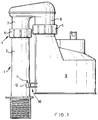
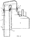
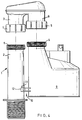
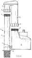
- Figs. 1 to 3 show side elevational views (Fig. 2 being in longitudinal section) of various syphon apparatus according to the invention assembled;
- syphon apparatus 1 for a cistern, comprising interconnectible syphon portions 2, 3 for assembly to provide a syphon apparatus 1 of variable dimension.
- the apparatus 1 is in three pieces.
- portion 2 which is a downleg, can be provided in a variety of lengths, say in eight different lengths as in the embodiments shown whereby the syphon apparatus 1 can be mounted in a variety of lengths of cistern, and in a variety of base shape or dimensions of cisterns for example, round, square, oval or parallelepiped.
- interconnecting means 4 such as a double start nut 5 and thread 6 arrangement on respective downwardly and upwardly (in use) facing portions, with a seal means such as an O-ring 7 incorporated therein.
- the portion 3 is a "U" tube, a leg 8 of which connects with a bell housing 9 or syphon body.
- the leg 8 may be provided in a variety of lengths like the downleg 2, for example eight lengths so that the apparatus 1 can be mounted in a variety of cisterns of different size.
- the leg 8 is attached to the body 9 by associated nut 5 and thread 6, and O-ring 7 and is then slid down to connect with the leg 2.
- the downleg 2 nut 5 is then tightened up to provide an assembled apparatus.
- the downleg 2 and bell housing 9 are also interconnectible by sliding interconnectible means 10.
- this comprises an upstanding spigot 11 on a bracket on the leg and a socket or through bore 12 in a bracket projecting from the bell housing 9.
- the part 3 is offered up to and lowered towards the part 2 and, with the spigot 11 and socket 12 aligned, the spigot 11 enters the socket 12 in effect to tie the two parts 2, 3 together.
- the parts 2, 3 can be disconnected by lifting the part 3 of the part 2 when the nut 5 is unscrewed, so lifting the socket 12 clear of the spigot 11.
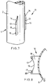
- Figs. 7 and 8 the upper part of the leg is not shown, and is identical to the parts shown in Figs. 1 to 6, as is the part 3 which is also not shown and which rises from the bell housing 9 in the manner shown in Figs. 1-6.
- Figs. 7 and 8 there is shown an embodiment in which the leg 2 and bell housing 9 are tied together by interconnectible means 10 in the form of a slidable connection comprising two opposed tongues or wings 13 which are integral with and project from the external surface of the leg 2 on a chord thereof.
- Each tongue or wing 13 projects outwardly from the body 2, and has an upper inclined or tapered part 14 leading to a part 15 which is substantially parallel to the longitudinal arm of the leg 2.
- One tongue or wing 13 has a latch means in the from of a notch or indent 16.
- Complementary interconnection means comprises a groove defined by two facing groove parts 17 in a bracket 18 which is integral with and projects from the bell housing 9 and which bracket 18 has a concave part 19 to accommodate the curve of the body of the leg 2 in use.
- the lateral extent of the groove 17 defined by the groove parts is equal to or just greater than the lateral extent of the tongues or wings 13, and the width of the groove 17 is equal to or just greater than the thickness of the material of the tongues on wings 13.
- the bracket 18 slides over the tongues or wings 13 as those tongues enter the groove 17.
- the bracket 18 slides down to the latch or recess 16, and a part 20 of the bracket 18 can snap engage therein to provide firm fixing.
- the syphon apparatus so assembled, as with the Figs. 1 - 6 embodiments, is by the interconnection means 10 rendered a rigid structure which is tied together by the interconnection means so that even when stresses occur in use, a skewing or canting tendency is overcome and the parts 2, 3 of the syphon apparatus 1 remain in desired mutual relationship. This helps to avoid leakage from the base of a cistern in which the apparatus is installed as there is no stress placed on the connection of the downleg with the base of the cistern.
- the syphon apparatus may be in two parts, rather than the three parts illustrated.
- the part 3 and bell housing 9 may form a J-shape part.
Landscapes
- Health & Medical Sciences (AREA)
- Life Sciences & Earth Sciences (AREA)
- Engineering & Computer Science (AREA)
- Hydrology & Water Resources (AREA)
- Public Health (AREA)
- Water Supply & Treatment (AREA)
- Jet Pumps And Other Pumps (AREA)
- Orthopedics, Nursing, And Contraception (AREA)
- Casings For Electric Apparatus (AREA)
- Furniture Connections (AREA)
- Legs For Furniture In General (AREA)
Applications Claiming Priority (4)
| Application Number | Priority Date | Filing Date | Title |
|---|---|---|---|
| GB9025784 | 1990-11-27 | ||
| GB909025784A GB9025784D0 (en) | 1990-11-27 | 1990-11-27 | Syphon apparatus |
| GB909025807A GB9025807D0 (en) | 1990-11-28 | 1990-11-28 | Syphon apparatus |
| GB9025807 | 1990-11-28 |
Publications (1)
| Publication Number | Publication Date |
|---|---|
| EP0488543A1 true EP0488543A1 (fr) | 1992-06-03 |
Family
ID=26298021
Family Applications (1)
| Application Number | Title | Priority Date | Filing Date |
|---|---|---|---|
| EP91310330A Withdrawn EP0488543A1 (fr) | 1990-11-27 | 1991-11-07 | Dispositif à siphon |
Country Status (4)
| Country | Link |
|---|---|
| EP (1) | EP0488543A1 (fr) |
| GB (1) | GB2250304B (fr) |
| IE (1) | IE69261B1 (fr) |
| PT (1) | PT99607A (fr) |
Cited By (1)
| Publication number | Priority date | Publication date | Assignee | Title |
|---|---|---|---|---|
| FR2921082A1 (fr) * | 2007-09-19 | 2009-03-20 | Siamp Cedap Sa Monegasque | "dispositif de chasse d'eau a siphon reglable en hauteur" |
Families Citing this family (3)
| Publication number | Priority date | Publication date | Assignee | Title |
|---|---|---|---|---|
| GB201021651D0 (en) * | 2010-12-21 | 2011-02-02 | Dudley Thomas Ltd | Draining apparatus |
| GB2547257B (en) * | 2016-02-12 | 2019-08-28 | Fluidmaster | Improved syphon |
| GB202000548D0 (en) * | 2020-01-14 | 2020-02-26 | Dudley Thomas Ltd | Cistern assembly |
Citations (3)
| Publication number | Priority date | Publication date | Assignee | Title |
|---|---|---|---|---|
| GB802838A (en) * | 1956-06-15 | 1958-10-15 | R & A G Crossland Ltd | Improvements relating to flushing-cistern syphons |
| GB2083851A (en) * | 1980-09-06 | 1982-03-31 | Dudley Thomas Ltd | Siphonic unit for flushing cisterns |
| EP0183337A2 (fr) * | 1984-11-30 | 1986-06-04 | Thomas Dudley Limited | Siphon pour réservoir de chasse d'eau |
Family Cites Families (4)
| Publication number | Priority date | Publication date | Assignee | Title |
|---|---|---|---|---|
| GB2092197A (en) * | 1981-01-29 | 1982-08-11 | Charmoy George Joseph Marie Ma | Cistern siphon units |
| GB2173833A (en) * | 1985-04-16 | 1986-10-22 | David John Lincoln | Syphon unit for flushing w.c. cistern |
| GB2174121A (en) * | 1985-04-20 | 1986-10-29 | George Thomas Edmund Davies | Detachable syphon for a W.C. cistern |
| GB9008226D0 (en) * | 1990-04-11 | 1990-06-13 | Polypipe Plc | Syphon apparatus |
-
1991
- 1991-11-07 GB GB9123650A patent/GB2250304B/en not_active Expired - Lifetime
- 1991-11-07 EP EP91310330A patent/EP0488543A1/fr not_active Withdrawn
- 1991-11-13 IE IE394591A patent/IE69261B1/en not_active IP Right Cessation
- 1991-11-26 PT PT9960791A patent/PT99607A/pt not_active Application Discontinuation
Patent Citations (3)
| Publication number | Priority date | Publication date | Assignee | Title |
|---|---|---|---|---|
| GB802838A (en) * | 1956-06-15 | 1958-10-15 | R & A G Crossland Ltd | Improvements relating to flushing-cistern syphons |
| GB2083851A (en) * | 1980-09-06 | 1982-03-31 | Dudley Thomas Ltd | Siphonic unit for flushing cisterns |
| EP0183337A2 (fr) * | 1984-11-30 | 1986-06-04 | Thomas Dudley Limited | Siphon pour réservoir de chasse d'eau |
Cited By (2)
| Publication number | Priority date | Publication date | Assignee | Title |
|---|---|---|---|---|
| FR2921082A1 (fr) * | 2007-09-19 | 2009-03-20 | Siamp Cedap Sa Monegasque | "dispositif de chasse d'eau a siphon reglable en hauteur" |
| EP2039838A1 (fr) * | 2007-09-19 | 2009-03-25 | Siamp Cedap | Dispositif de chasse d'eau à siphon reglable en hauteur |
Also Published As
| Publication number | Publication date |
|---|---|
| IE69261B1 (en) | 1996-08-21 |
| GB9123650D0 (en) | 1992-01-02 |
| GB2250304B (en) | 1995-05-10 |
| PT99607A (pt) | 1993-12-31 |
| IE913945A1 (en) | 1992-06-03 |
| GB2250304A (en) | 1992-06-03 |
Similar Documents
| Publication | Publication Date | Title |
|---|---|---|
| EP3871577B1 (fr) | Système de toilette | |
| US6634034B2 (en) | Adjustable toilet flange assembly | |
| JP2020073368A (ja) | 浮動ユニットと浮動ユニットから組み立てられた浮動構造体 | |
| DK0832840T3 (da) | Anordning til at løfte præfabrikerede byggeelementer, navnlig dem fremstillet af beton eller lignende | |
| KR970059382A (ko) | 시어 커넥터용 앵커 부시, 시어 커넥터, 및 내부식성 고정물의 제조 방법 | |
| US3285289A (en) | Adjustable clean-out means | |
| US6547285B1 (en) | Fixing arrangement for sanitary components | |
| US3389560A (en) | Diffusion well construction | |
| IE913945A1 (en) | Demountable syphon for a WC cistern | |
| US4649953A (en) | Siphon assembly for flushing cisterns | |
| US4445237A (en) | Close coupled water-closet combination and adapter | |
| EP3757315A1 (fr) | Insert de coffrage | |
| EP1913839A2 (fr) | Élément de couplage pour montants de table | |
| US5090739A (en) | Plumbing sleeve | |
| KR200405550Y1 (ko) | 파이프 써포트 | |
| KR101368593B1 (ko) | 양변기 배수구 연결장치 | |
| CN219298356U (zh) | 一种快速拆装的排水塞连动装置 | |
| DE50014080D1 (de) | Fahrspurtrenneinrichtung | |
| GB2409009A (en) | A telescopic connection structure | |
| KR102864669B1 (ko) | 리모델링 바닥 슬리브 | |
| KR100815192B1 (ko) | 배수트랩 연결구 | |
| KR200202910Y1 (ko) | 조립식 암거용 앵커플레이트 | |
| KR102274283B1 (ko) | 건축설비용 슬리브 고정장치 | |
| JPH0577816B2 (fr) | ||
| KR910006149Y1 (ko) | 전선관용 접속상자 |
Legal Events
| Date | Code | Title | Description |
|---|---|---|---|
| PUAI | Public reference made under article 153(3) epc to a published international application that has entered the european phase |
Free format text: ORIGINAL CODE: 0009012 |
|
| AK | Designated contracting states |
Kind code of ref document: A1 Designated state(s): AT BE CH DE DK ES FR GB GR IT LI LU NL SE |
|
| 17P | Request for examination filed |
Effective date: 19921109 |
|
| 17Q | First examination report despatched |
Effective date: 19930628 |
|
| STAA | Information on the status of an ep patent application or granted ep patent |
Free format text: STATUS: THE APPLICATION IS DEEMED TO BE WITHDRAWN |
|
| 18D | Application deemed to be withdrawn |
Effective date: 19931109 |