EP0488577B1 - Manhattan-Strassen-Netzwerk mit Ringarchitektur - Google Patents
Manhattan-Strassen-Netzwerk mit Ringarchitektur Download PDFInfo
- Publication number
- EP0488577B1 EP0488577B1 EP91310680A EP91310680A EP0488577B1 EP 0488577 B1 EP0488577 B1 EP 0488577B1 EP 91310680 A EP91310680 A EP 91310680A EP 91310680 A EP91310680 A EP 91310680A EP 0488577 B1 EP0488577 B1 EP 0488577B1
- Authority
- EP
- European Patent Office
- Prior art keywords
- network
- rings
- stations
- loop
- station
- Prior art date
- Legal status (The legal status is an assumption and is not a legal conclusion. Google has not performed a legal analysis and makes no representation as to the accuracy of the status listed.)
- Expired - Lifetime
Links
- 239000013307 optical fiber Substances 0.000 claims description 4
- 239000000835 fiber Substances 0.000 claims description 3
- 230000006870 function Effects 0.000 description 8
- 230000003139 buffering effect Effects 0.000 description 5
- 230000005540 biological transmission Effects 0.000 description 4
- 230000002457 bidirectional effect Effects 0.000 description 3
- 238000004891 communication Methods 0.000 description 2
- 238000000034 method Methods 0.000 description 2
- RYGMFSIKBFXOCR-UHFFFAOYSA-N Copper Chemical compound [Cu] RYGMFSIKBFXOCR-UHFFFAOYSA-N 0.000 description 1
- 108700026140 MAC combination Proteins 0.000 description 1
- 229910052802 copper Inorganic materials 0.000 description 1
- 239000010949 copper Substances 0.000 description 1
- 230000003247 decreasing effect Effects 0.000 description 1
- 230000001934 delay Effects 0.000 description 1
- 230000001419 dependent effect Effects 0.000 description 1
- 239000000975 dye Substances 0.000 description 1
- 230000003287 optical effect Effects 0.000 description 1
- 238000009877 rendering Methods 0.000 description 1
- 230000004044 response Effects 0.000 description 1
- 230000001360 synchronised effect Effects 0.000 description 1
Images



Classifications
-
- H—ELECTRICITY
- H04—ELECTRIC COMMUNICATION TECHNIQUE
- H04L—TRANSMISSION OF DIGITAL INFORMATION, e.g. TELEGRAPHIC COMMUNICATION
- H04L12/00—Data switching networks
- H04L12/28—Data switching networks characterised by path configuration, e.g. LAN [Local Area Networks] or WAN [Wide Area Networks]
- H04L12/46—Interconnection of networks
- H04L12/4637—Interconnected ring systems
Definitions
- This invention relates to telecommunications networks.
- LANs local area networks
- LANs are telecommunications networks which interconnect a plurality of stations which are typically located in a relatively compact geographical area.
- the long distance telecommunications network spreads over an enormous geographical area.
- the differences, e.g., geographical area, between the two types of networks frequently lead to design differences.
- the physical location of nodes i.e., a point where two or more lines intersect, is determined primarily by geography in long distance networks but in LANs the location of nodes is frequently determined by other considerations, such as the frequency of communications between two stations, i.e., how frequently two stations talk to each other, transmission medium, transmission delays, etc., rather than by geography.
- Token rings may be either synchronous or asynchronous.
- the loop system described is unidirectional and consequently suffers several drawbacks, including single paths between two stations, thereby rendering the system subject to catastrophic failure and decreased efficiency if some portions of the loop are used more extensively than are other portions.
- bidirectional loop systems such as the fiber distributed data interface
- This system commonly referred to by the acronym FDDI, is a token ring network which uses two rings that are referred to as the primary and the secondary ring. Information flows in opposite directions in the two rings, but only one loop is typically used in the absence of faults.
- the stations are designated as either Class A or Class B stations. Class A stations have two inputs and two outputs with one out of each connected to the primary ring and to the secondary ring. Class B stations have a single input and a single output and are connected only to the primary ring. Each station can identify faults in the rings and initiate steps so that the network reconfigures itself and remains in operation, i.e., the system uses distributed control.
- each station has means for switching packets, i.e., a defined set of bits, between the primary ring and the secondary ring which is generally used only if faults are present.
- this switching means as well as the means for transmitting packets on the secondary loop, is not much used in the absence of faults.
- any two stations are connected by a very limited number of possible paths, and the number does not increase as the number of stations increases.
- transfers between loops are accomplished with apparatus termed bridges which occupy positions on the loop but perform no station functions.
- mesh networks Such networks have pluralities of intersecting horizontal and vertical lines, i.e., paths, with a station or other apparatus located at the points of intersection or nodes.
- a mesh network thus has a plurality of point-to-point communication paths or channels.
- Mesh networks are advantageously employed, as compared to loop networks, because they provide numerous alternative paths between stations, thus making the network more resistant to faults than are loop systems and providing alternative routes in times of heavy usage.
- One mesh network is termed the Manhattan Street Network and is commonly referred to by the acronym MSN. See, e.g., the article by Maxemchuk in A.T.&T. Technical Journal, pp. 1659-1685, September 1985 for a detailed description of an MSN.
- the name MSN is descriptive of the network because it is a mesh with a first plurality of paths running horizontally and a second plurality of paths running vertically.
- the first and second pluralities are referred to as streets and avenues, respectively, because streets and avenues in the city of Manhattan run generally east-west (horizontal) and north-south (vertical), respectively.
- Each point where the first and second pluralities intersect is a node with two inputs and two outputs.
- Each packet is identified by two coordinates (one for the row and one for the column) for the source and by two coordinates for the destination.
- the MSN is a relatively efficient system because there is a choice of routes between the source and destination, thereby permitting both faulty routes and busy nodes to be avoided.
- US-A-4797882 discloses a grid-based mesh network with even numbers of alternatingly directed rows and columns. Devices are attached by way of nodes which exist at the intersections of rows and columns. The extremes of the grid are connected to form a three-dimensional network on the surface of a sphere. The strategy at each node requires that every packet arriving on an incoming link must leave on an outgoing link, so there is no need for any packet buffering in the node.
- EP-A-0242765 discloses a telecommunications network comprising a plurality of primary token rings, generally arranged in a first direction and forming a plurality of rows, at least one secondary token ring generally arranged in a second direction and forming a column, and a plurality of stations comprising first and second pairs of input and output terminals, said first pair and said second pair of said input and output terminals being connected to a primary ring and a secondary ring, respectively, and station further comprising means for switching packets between said primary and said secondary rings.
- the stations also comprise means for handling tokens in both rings connected to the station.
- at least one of the rings comprises an optical fiber.
- the network has a plurality of secondary token rings.
- at least one of the primary rings and at least one of the secondary rings are connected to the same station and form a fiber distributed data interface network.
- at least one of the stations comprises a concentrator and the network further has a local area network connected to the concentrator.
- the stations in the network comprise means for determining routes between source and destination stations.
- FIG. 1 The configuration of an exemplary token loop network embodying the invention is depicted in FIG. 1.
- the network shown is a 4 x 4 FDDI network, i.e., it has 16 stations and 4 loops 11-14 arranged generally in a first direction (horizontal) and 4 loops 21-24 arranged generally in a second direction (vertical).
- the stations are thus interconnected by a plurality of generally horizontal (first direction) loops 11-14 and a plurality of generally vertical (second direction) loops 21-24. Each horizontal loop and each vertical loop represent a row and a column, respectively.
- Both the horizontal and vertical loops pass through the stations as schematically indicated.
- Each station has first and second pairs of input and output terminals with the first and second pairs being connected to the primary and secondary loop, respectively.
- the horizontal and vertical loops can be referred to as primary and secondary rings, respectively, or vice versa.
- the primary and secondary rings are arranged in first and second directions, respectively.
- the rings are token rings and that the direction refers to direction of packet propagation, indicated by the arrows on the loops, on the drawing and need not correspond to geographical direction.
- the network depicted can handle both voice and data as well as the necessary signal and control information.
- the choice of the ring designated as primary is arbitrary in describing the network. That is, the terms primary and secondary are interchangeable in describing the network.
- the network depicted is a combined MSN and FDDI network which, for reasons of brevity, may be referred to as a M-FDDI network. That is, the nodes of a FDDI primary ring are the stations on a row or street and the nodes of a FDDI secondary ring are the stations on a column or avenue.
- bidirectional token ring systems other than FDDI may be used. Both the primary and secondary rings are utilized at the same time and each ring may have a token at the same time. Both primary and secondary rings will have comparable utilization and thereby increase system utilization, as compared to the conventional bidirectional ring system. All rings may operate at the same time.
- the ring i.e., transmission media, is formed from optical fibers.
- the network depicted is an idealized symmetrical network.
- the network need not be symmetrical, i.e., it need not have the same number of rows and columns, and may have, e.g., missing nodes (stations) and/or partial rows or partial columns.
- the node capacity of the network depicted is small because the network depicted itself is small, the capacity of actual networks may be enormous and will frequently be larger than that of the network depicted. For example, if each FDDI loop can support n nodes, the capacity of the network is n x n if all possible nodes have stations.
- the network is a token ring network, it is configured as a mesh network and has the high degree of fault tolerance typical of mesh networks as will be apparent after consideration of FIG. 2.
- the network depicted is the same network that was depicted in FIG. 1 except for the fault 30, e.g., break, in horizontal loop 12 between station (2,2) and station (2,3). Assume that station (2,1) wants to communicate with station (2,4). It cannot do so entirely on loop 12 because of the fault. The packets must change from one loop to another loop to avoid the fault, and a switching function occurs as the packets move from loop to loop.
- An illustrative alternative loop is shown in bold face lines in FIG. 2.
- the packet moves, e.g., from station (2,1) to station (2,2) where it switches to vertical loop 22 and moves to station (1,2). It then switches to horizontal loop 11 and moves to stations (1,3) and (1,4). At the latter station, it switches to vertical loop 24 and goes through station (4,4) and (3,4) to reach station (2,4). This is only one of many possible routes.
- the optimum path depends upon the number of interloop transfers rather than the number of intrastation transfers because the switching function,including buffering, performed when packets are moved from one loop to another loop is less efficient than is moving packets from station to station on the same loop.
- the packets rotate around a loop, as they do in any token ring system, and a switching function occurs only when the packets move from one loop to another loop.
- the node when a packet is switched from a primary loop to a secondary loop, the node must perform switching functions such as address recognition, route determination, buffering of packets, and copying of the packet from one ring to the other ring.
- the node does not initially know whether switching must occur, so some buffering of the incoming packet is performed until the destination address is decoded. Buffering is also required until the destination address of the token for the second loop is received and the packet may be transmitted.
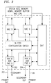
- FIG. 3 is a schematic representation of the architecture of a node, i.e., station, according to this invention. Depicted are primary input and output 301 and 302, respectively, and secondary input and output 303 and 304, respectively. Further depicted are the conventional and well-known portions of the FDDI station specification, including the following four portions: the physical layer medium dependent (PMD) A and B, the physical layer protocol (PHY) A and B, the medium access control (MAC) and the station management (SMT).
- the PMD corresponds to the lower sublayer of the open system interconnect (OSI) physical layer and specifies the optical transmitter and receiver.
- the PHY corresponds to the upper sublayer and specifies the PHY functions.
- the MAC protocol corresponds to the lower sublayer of the OSI data link layer and defines rules for medium access, addressing, frame formats, error checking and token management.
- the SMT standard specifies system management functions and the control required for the best performance or connectivity requirements of a station on the FDDI network. It also includes components for control of the token as well as means for determining routes between two stations. Also depicted are the system bus, memory administration, memory, buffer, and central processor unit.
- the station is generally equivalent to two stations, i.e., one station for the primary ring and one station for the secondary ring with a switching function also present.
- the components depicted will, when necessary, switch packets from the primary ring to the secondary ring and vice versa.
- the components also manage the token. These components are well known to those skilled in the art and further description is not required for those skilled in the art to implement this invention.
- the originating station i.e., source node
- the originating station will choose a first degree route and transmit the packets on the selected loop.
- the packet propagates on this loop until it reaches a node having a coordinate which matches one of the destination coordinates.
- the packet is copied onto the ring with the same coordinate.
- the packet propagates on this ring until the destination is reached.
- Route selection with faults present is generally similar to the process just described and that described with respect to FIG. 2. However, at each node a determination is made as to whether either of the next two neighboring nodes is faulty. If not, the packet is sent to the next node on the same loop. If dyes, the packet is switched to the loop with the operating node rather than to the loop with the fault.
- either the horizontal or vertical loops may be first initialized.
- the vertical or horizontal loops are then initialized using the values obtained for the nodes in the first initialization. The process is continued until the values obtained converge to the desired degree.
- the addition of a node to the network is relatively simple as will be appreciated after consideration of FIG. 4.
- the network depicted is similar to that depicted in FIG. 1 except that horizontal loop 13 was originally absent and was added to the original configuration of the network to accommodate station (3,2). That is, the original network was a 3 x 4 network and did not have station (3,2).
- new stations may be added to either a vertical loop or to a horizontal loop. If the station is added to a vertical loop between two stations, a new horizontal loop is created with the new station as its sole station. If the new station is added to a horizontal loop, a new vertical loop is created with the new station as its sole station.
- the invention has been described with respect to a two-dimensional implementation, but it can be implemented in three dimensions using standard expansion practices.
- a brief discussion of how the network can be extended to a multistory building will suffice to illustrate the general principles.
- the building is represented by a Class A concentrator or hub.
- Class B stations within the building are connected to the concentrator thereby adding a vertical dimension to the two horizontal dimensions already present.
- topologies other than rings, e.g., stars or trees, may be used in the third or vertical dimension.
- FDDI optical fiber
- the invention may be practiced with other transmission media, such as copper wires and free space, and other loop configurations.
- the invention was discussed in terms of LANs, it may also be implemented with long-distance networks.
Landscapes
- Engineering & Computer Science (AREA)
- Computer Networks & Wireless Communication (AREA)
- Signal Processing (AREA)
- Small-Scale Networks (AREA)
Claims (4)
- Telekommunikationsnetz mit folgenden:einer Mehrzahl von im allgemeinen in einer ersten Richtung angeordneten und eine Mehrzahl von Zeilen bildenden Erst-Token-Ringen (11-14);einer Mehrzahl von im allgemeinen in einer zweiten Richtung angeordneten und eine Mehrzahl von Spalten bildenden Zweit-Token-Ringen (21-24);einer Mehrzahl von Endgeräten (1.1-4.4); und wobeimindestens einer der besagten Ringe (11-14,21-24) eine Glasfaser umfaßt und mindestens einer der besagten Erstringe und mindestens einer der besagten Zweitringe mit demselben Endgerät verbunden sind;dadurch gekennzeichnet, daß jedes besagte Endgerät ein Endgerät mit Datenanschluß mit Signalverteilung über Glasfaser und erste und zweite Paare (301-302, 303-304) von Eingangs- und Ausgangsanschlüssen umfaßt, wobei die besagten Endgeräte durch die besagte Mehrzahl von Erstringen und besagte Mehrzahl von Zweitringen miteinander verbunden sind, wobei besagtes erstes Paar (301-302) und besagtes zweites Paar (303-304) der besagten Eingangs- und Ausgangsanschlüsse mit einem Erstring bzw. einem Zweitring verbunden sind und jedes der besagten Endgeräte weiterhin Mittel zum Umschalten von Paketen zwischen besagten Erst- und besagten Zweitringen umfaßt, wobei die besagte Mehrzahl von Erst-Token-Ringen und besagte Mehrzahl von Zweit-Token-Ringen in einem Manhattan-Street-Netz angeordnet sind.
- Netz nach Anspruch 1, wobei mindestens eines der besagten Endgeräte einen Konzentrator umfaßt und das besagte Netz weiterhin ein mit dem besagten Konzentrator verbundenes Ortsnetz umfaßt.
- Netz nach Anspruch 2, wobei besagte Endgeräte Mittel zum Bestimmen von Leitwegen zwischen mindestens zwei Endgeräten umfassen.
- Netz nach Anspruch 1, wobei besagte Endgeräte Mittel zum Bearbeiten von Tokens im besagten Erst- und Zweit-Ringen umfassen.
Applications Claiming Priority (2)
| Application Number | Priority Date | Filing Date | Title |
|---|---|---|---|
| US07/618,447 US5289467A (en) | 1990-11-27 | 1990-11-27 | Manhattan street network with loop architecture |
| US618447 | 1990-11-27 |
Publications (2)
| Publication Number | Publication Date |
|---|---|
| EP0488577A1 EP0488577A1 (de) | 1992-06-03 |
| EP0488577B1 true EP0488577B1 (de) | 1996-09-11 |
Family
ID=24477726
Family Applications (1)
| Application Number | Title | Priority Date | Filing Date |
|---|---|---|---|
| EP91310680A Expired - Lifetime EP0488577B1 (de) | 1990-11-27 | 1991-11-20 | Manhattan-Strassen-Netzwerk mit Ringarchitektur |
Country Status (4)
| Country | Link |
|---|---|
| US (1) | US5289467A (de) |
| EP (1) | EP0488577B1 (de) |
| JP (1) | JPH04306938A (de) |
| DE (1) | DE69122049T2 (de) |
Cited By (4)
| Publication number | Priority date | Publication date | Assignee | Title |
|---|---|---|---|---|
| WO2003022774A1 (en) | 2001-09-10 | 2003-03-20 | 3M Innovative Properties Company | Toughened fibre-reinforced cementitious composites |
| US6692823B2 (en) | 2001-12-19 | 2004-02-17 | 3M Innovative Properties Company | Microfibrillated articles comprising hydrophillic component |
| US6753080B1 (en) | 2002-01-29 | 2004-06-22 | 3M Innovative Properties Company | Receptor medium having a microfibrillated surface |
| US7192643B2 (en) | 2001-08-22 | 2007-03-20 | 3M Innovative Properties Company | Toughened cementitious composites |
Families Citing this family (7)
| Publication number | Priority date | Publication date | Assignee | Title |
|---|---|---|---|---|
| US5182747A (en) * | 1990-06-26 | 1993-01-26 | International Business Machines Corporation | Method for controlling the insertion of stations into fddi network |
| JPH07226736A (ja) * | 1994-02-14 | 1995-08-22 | Hitachi Ltd | メッシュ網における障害復旧方法 |
| US5602838A (en) * | 1994-12-21 | 1997-02-11 | Lucent Technologies Inc. | Global multi-satellite network |
| US5799015A (en) * | 1996-05-13 | 1998-08-25 | Lockheed Martin Corporation | Recirculation routes in switching networks used with scalable coherent interfaces |
| US6055228A (en) * | 1996-12-23 | 2000-04-25 | Lsi Logic Corporation | Methods and apparatus for dynamic topology configuration in a daisy-chained communication environment |
| US6108345A (en) * | 1997-05-30 | 2000-08-22 | 3Com Corporation | Configurable Wan/Lan bridge |
| KR101979783B1 (ko) * | 2015-03-30 | 2019-08-28 | 에스케이하이닉스 주식회사 | 전력 관리를 수행하는 반도체 장치 및 그 동작 방법 |
Family Cites Families (10)
| Publication number | Priority date | Publication date | Assignee | Title |
|---|---|---|---|---|
| NO123200B (de) * | 1967-11-23 | 1971-10-11 | Svenska Handelsbanken | |
| EP0109964B1 (de) * | 1982-11-26 | 1986-04-23 | International Business Machines Corporation | Synchronisierung in einem Nachrichtennetz aus miteinander verbundenen Ringen |
| JPH0767112B2 (ja) * | 1983-12-23 | 1995-07-19 | 株式会社日立製作所 | 通信ネツトワ−クシステム |
| US4742511A (en) * | 1985-06-13 | 1988-05-03 | Texas Instruments Incorporated | Method and apparatus for routing packets in a multinode computer interconnect network |
| CA1252168A (en) * | 1985-07-24 | 1989-04-04 | Kenneth A. Bobey | Communications network |
| US4797882A (en) * | 1985-10-02 | 1989-01-10 | American Telephone And Telegraph Company, At&T Bell Laboratories | Mesh-based switching network |
| DD248447A1 (de) * | 1986-04-21 | 1987-08-05 | Geraete & Regler Werke Veb | Anordnung zur informationsuebertragung in hierarchisch gegliederten automatisierungsanlagen |
| US4933933A (en) * | 1986-12-19 | 1990-06-12 | The California Institute Of Technology | Torus routing chip |
| JPH01208934A (ja) * | 1988-02-16 | 1989-08-22 | Sumitomo Electric Ind Ltd | ノード装置 |
| US4979167A (en) * | 1988-12-02 | 1990-12-18 | Advanced Micro Devices, Inc. | Methods and apparatus for performing restricted token operations on an FDDI network |
-
1990
- 1990-11-27 US US07/618,447 patent/US5289467A/en not_active Expired - Lifetime
-
1991
- 1991-11-20 DE DE69122049T patent/DE69122049T2/de not_active Expired - Fee Related
- 1991-11-20 EP EP91310680A patent/EP0488577B1/de not_active Expired - Lifetime
- 1991-11-27 JP JP3311152A patent/JPH04306938A/ja active Pending
Cited By (4)
| Publication number | Priority date | Publication date | Assignee | Title |
|---|---|---|---|---|
| US7192643B2 (en) | 2001-08-22 | 2007-03-20 | 3M Innovative Properties Company | Toughened cementitious composites |
| WO2003022774A1 (en) | 2001-09-10 | 2003-03-20 | 3M Innovative Properties Company | Toughened fibre-reinforced cementitious composites |
| US6692823B2 (en) | 2001-12-19 | 2004-02-17 | 3M Innovative Properties Company | Microfibrillated articles comprising hydrophillic component |
| US6753080B1 (en) | 2002-01-29 | 2004-06-22 | 3M Innovative Properties Company | Receptor medium having a microfibrillated surface |
Also Published As
| Publication number | Publication date |
|---|---|
| JPH04306938A (ja) | 1992-10-29 |
| DE69122049D1 (de) | 1996-10-17 |
| US5289467A (en) | 1994-02-22 |
| EP0488577A1 (de) | 1992-06-03 |
| DE69122049T2 (de) | 1997-01-23 |
Similar Documents
| Publication | Publication Date | Title |
|---|---|---|
| US6728205B1 (en) | Method and apparatus for automatic protection switching | |
| US6047331A (en) | Method and apparatus for automatic protection switching | |
| EP0844755B1 (de) | Verbindungsübertragungsnetzwerk | |
| US9825844B2 (en) | Network topology of hierarchical ring with recursive shortcuts | |
| US5606551A (en) | Bidirectional mesh network | |
| Karol et al. | High-performance optical local and metropolitan area networks: Enhancements of FDDI and IEEE 802.6 DQDB | |
| JPH0624366B2 (ja) | ネットワーク障害回復方式 | |
| JPH11511618A (ja) | 電気通信ネットワークにおける最適復旧ルートの決定論的選択 | |
| US6895182B1 (en) | Optical ring transmission system using squelch method | |
| EP0488577B1 (de) | Manhattan-Strassen-Netzwerk mit Ringarchitektur | |
| Finley Jr | Optical fibers in local area networks | |
| JP4017985B2 (ja) | 第3世代セルラーネットワーク | |
| JPH05199248A (ja) | 通信トリー構成装置、通信ネットワーク、及び送信方法 | |
| US5087911A (en) | Data communication network | |
| Brassil et al. | The Manhattan Street Network: a high performance, highly reliable metropolitan area network | |
| Maxemchuk et al. | A comparison of linear and mesh topologies-DQDB and the Manhattan street network | |
| AU607331B2 (en) | A telecomunications system and a method of transmitting information in a telecommunications system | |
| GB2199209A (en) | Optical communication systems | |
| EP2285046B1 (de) | Verfahren und vorrichtung zur realisierung der interaktion tangierender schutzringe für optische kanaldateneinheiten | |
| Kos et al. | Topological planning of communication networks | |
| RU2795451C1 (ru) | Универсальная система обмена данными | |
| Tong et al. | Design principles for multi-hop wavelength and time division multiplexed optical passive star networks | |
| Kartalopoulos | A Manhattan fiber distributed data interface architecture | |
| Krishnan et al. | Life beyond linear topologies (MANs) | |
| JPH1079757A (ja) | 通信ネットワークおよび論理パス経路選択方法 |
Legal Events
| Date | Code | Title | Description |
|---|---|---|---|
| PUAI | Public reference made under article 153(3) epc to a published international application that has entered the european phase |
Free format text: ORIGINAL CODE: 0009012 |
|
| AK | Designated contracting states |
Kind code of ref document: A1 Designated state(s): DE FR GB IT |
|
| 17P | Request for examination filed |
Effective date: 19921119 |
|
| RAP3 | Party data changed (applicant data changed or rights of an application transferred) |
Owner name: AT&T CORP. |
|
| 17Q | First examination report despatched |
Effective date: 19941206 |
|
| GRAH | Despatch of communication of intention to grant a patent |
Free format text: ORIGINAL CODE: EPIDOS IGRA |
|
| GRAH | Despatch of communication of intention to grant a patent |
Free format text: ORIGINAL CODE: EPIDOS IGRA |
|
| GRAA | (expected) grant |
Free format text: ORIGINAL CODE: 0009210 |
|
| AK | Designated contracting states |
Kind code of ref document: B1 Designated state(s): DE FR GB IT |
|
| ITF | It: translation for a ep patent filed | ||
| ET | Fr: translation filed | ||
| REF | Corresponds to: |
Ref document number: 69122049 Country of ref document: DE Date of ref document: 19961017 |
|
| PLBE | No opposition filed within time limit |
Free format text: ORIGINAL CODE: 0009261 |
|
| STAA | Information on the status of an ep patent application or granted ep patent |
Free format text: STATUS: NO OPPOSITION FILED WITHIN TIME LIMIT |
|
| 26N | No opposition filed | ||
| PGFP | Annual fee paid to national office [announced via postgrant information from national office to epo] |
Ref country code: FR Payment date: 20001025 Year of fee payment: 10 |
|
| PGFP | Annual fee paid to national office [announced via postgrant information from national office to epo] |
Ref country code: GB Payment date: 20001026 Year of fee payment: 10 |
|
| PGFP | Annual fee paid to national office [announced via postgrant information from national office to epo] |
Ref country code: DE Payment date: 20001229 Year of fee payment: 10 |
|
| PG25 | Lapsed in a contracting state [announced via postgrant information from national office to epo] |
Ref country code: GB Free format text: LAPSE BECAUSE OF NON-PAYMENT OF DUE FEES Effective date: 20011120 |
|
| REG | Reference to a national code |
Ref country code: GB Ref legal event code: IF02 |
|
| PG25 | Lapsed in a contracting state [announced via postgrant information from national office to epo] |
Ref country code: DE Free format text: LAPSE BECAUSE OF NON-PAYMENT OF DUE FEES Effective date: 20020702 |
|
| GBPC | Gb: european patent ceased through non-payment of renewal fee |
Effective date: 20011120 |
|
| PG25 | Lapsed in a contracting state [announced via postgrant information from national office to epo] |
Ref country code: FR Free format text: LAPSE BECAUSE OF NON-PAYMENT OF DUE FEES Effective date: 20020730 |
|
| REG | Reference to a national code |
Ref country code: FR Ref legal event code: ST |
|
| REG | Reference to a national code |
Ref country code: FR Ref legal event code: ST |
|
| PG25 | Lapsed in a contracting state [announced via postgrant information from national office to epo] |
Ref country code: IT Free format text: LAPSE BECAUSE OF NON-PAYMENT OF DUE FEES;WARNING: LAPSES OF ITALIAN PATENTS WITH EFFECTIVE DATE BEFORE 2007 MAY HAVE OCCURRED AT ANY TIME BEFORE 2007. THE CORRECT EFFECTIVE DATE MAY BE DIFFERENT FROM THE ONE RECORDED. Effective date: 20051120 |