EP0488774A1 - Auswuchtung eines Werkzeughalters - Google Patents
Auswuchtung eines Werkzeughalters Download PDFInfo
- Publication number
- EP0488774A1 EP0488774A1 EP91311096A EP91311096A EP0488774A1 EP 0488774 A1 EP0488774 A1 EP 0488774A1 EP 91311096 A EP91311096 A EP 91311096A EP 91311096 A EP91311096 A EP 91311096A EP 0488774 A1 EP0488774 A1 EP 0488774A1
- Authority
- EP
- European Patent Office
- Prior art keywords
- balancers
- primary
- balancer
- spindle
- slide
- Prior art date
- Legal status (The legal status is an assumption and is not a legal conclusion. Google has not performed a legal analysis and makes no representation as to the accuracy of the status listed.)
- Ceased
Links
- 238000003754 machining Methods 0.000 claims abstract description 23
- 238000006073 displacement reaction Methods 0.000 abstract description 12
- 238000005520 cutting process Methods 0.000 description 17
- 230000005484 gravity Effects 0.000 description 16
- 230000007935 neutral effect Effects 0.000 description 5
- 230000000694 effects Effects 0.000 description 3
- 230000033001 locomotion Effects 0.000 description 3
- 230000009467 reduction Effects 0.000 description 3
- 229910000831 Steel Inorganic materials 0.000 description 2
- 239000002184 metal Substances 0.000 description 2
- 239000010959 steel Substances 0.000 description 2
- 230000009471 action Effects 0.000 description 1
- 230000002411 adverse Effects 0.000 description 1
- 230000005540 biological transmission Effects 0.000 description 1
- 230000008859 change Effects 0.000 description 1
- 230000003247 decreasing effect Effects 0.000 description 1
- 230000006872 improvement Effects 0.000 description 1
- 230000010354 integration Effects 0.000 description 1
- 230000009545 invasion Effects 0.000 description 1
- 230000004044 response Effects 0.000 description 1
- 238000007493 shaping process Methods 0.000 description 1
- 239000000126 substance Substances 0.000 description 1
Images



Classifications
-
- B—PERFORMING OPERATIONS; TRANSPORTING
- B23—MACHINE TOOLS; METAL-WORKING NOT OTHERWISE PROVIDED FOR
- B23Q—DETAILS, COMPONENTS, OR ACCESSORIES FOR MACHINE TOOLS, e.g. ARRANGEMENTS FOR COPYING OR CONTROLLING; MACHINE TOOLS IN GENERAL CHARACTERISED BY THE CONSTRUCTION OF PARTICULAR DETAILS OR COMPONENTS; COMBINATIONS OR ASSOCIATIONS OF METAL-WORKING MACHINES, NOT DIRECTED TO A PARTICULAR RESULT
- B23Q5/00—Driving or feeding mechanisms; Control arrangements therefor
-
- B—PERFORMING OPERATIONS; TRANSPORTING
- B23—MACHINE TOOLS; METAL-WORKING NOT OTHERWISE PROVIDED FOR
- B23Q—DETAILS, COMPONENTS, OR ACCESSORIES FOR MACHINE TOOLS, e.g. ARRANGEMENTS FOR COPYING OR CONTROLLING; MACHINE TOOLS IN GENERAL CHARACTERISED BY THE CONSTRUCTION OF PARTICULAR DETAILS OR COMPONENTS; COMBINATIONS OR ASSOCIATIONS OF METAL-WORKING MACHINES, NOT DIRECTED TO A PARTICULAR RESULT
- B23Q11/00—Accessories fitted to machine tools for keeping tools or parts of the machine in good working condition or for cooling work; Safety devices specially combined with or arranged in, or specially adapted for use in connection with, machine tools
- B23Q11/0032—Arrangements for preventing or isolating vibrations in parts of the machine
- B23Q11/0035—Arrangements for preventing or isolating vibrations in parts of the machine by adding or adjusting a mass, e.g. counterweights
-
- Y—GENERAL TAGGING OF NEW TECHNOLOGICAL DEVELOPMENTS; GENERAL TAGGING OF CROSS-SECTIONAL TECHNOLOGIES SPANNING OVER SEVERAL SECTIONS OF THE IPC; TECHNICAL SUBJECTS COVERED BY FORMER USPC CROSS-REFERENCE ART COLLECTIONS [XRACs] AND DIGESTS
- Y10—TECHNICAL SUBJECTS COVERED BY FORMER USPC
- Y10T—TECHNICAL SUBJECTS COVERED BY FORMER US CLASSIFICATION
- Y10T408/00—Cutting by use of rotating axially moving tool
- Y10T408/76—Tool-carrier with vibration-damping means
-
- Y—GENERAL TAGGING OF NEW TECHNOLOGICAL DEVELOPMENTS; GENERAL TAGGING OF CROSS-SECTIONAL TECHNOLOGIES SPANNING OVER SEVERAL SECTIONS OF THE IPC; TECHNICAL SUBJECTS COVERED BY FORMER USPC CROSS-REFERENCE ART COLLECTIONS [XRACs] AND DIGESTS
- Y10—TECHNICAL SUBJECTS COVERED BY FORMER USPC
- Y10T—TECHNICAL SUBJECTS COVERED BY FORMER US CLASSIFICATION
- Y10T409/00—Gear cutting, milling, or planing
- Y10T409/30—Milling
- Y10T409/304312—Milling with means to dampen vibration
-
- Y—GENERAL TAGGING OF NEW TECHNOLOGICAL DEVELOPMENTS; GENERAL TAGGING OF CROSS-SECTIONAL TECHNOLOGIES SPANNING OVER SEVERAL SECTIONS OF THE IPC; TECHNICAL SUBJECTS COVERED BY FORMER USPC CROSS-REFERENCE ART COLLECTIONS [XRACs] AND DIGESTS
- Y10—TECHNICAL SUBJECTS COVERED BY FORMER USPC
- Y10T—TECHNICAL SUBJECTS COVERED BY FORMER US CLASSIFICATION
- Y10T74/00—Machine element or mechanism
- Y10T74/21—Elements
- Y10T74/2121—Flywheel, motion smoothing-type
- Y10T74/213—Damping by increasing frictional force
Definitions
- the present invention relates to a balancer attachment for the spindle of a machining apparatus which is capable of compensating any imbalance caused by deviation of the center of gravity of the spindle when displacing and putting an associated cutting tool in a desired radial position.
- the piece of metal In machining and shaping a piece of metal into a circular cross section the piece of metal is attached to the spindle end, and it is revolved at an increased speed to enable a stationary cutting tool to shape the workpiece into the cylindrical body. Assume that a part of workpiece which is not in cylindrical form is shaped into a circular cross section. Uneven distribution of the weight of the workpiece in the workspindle end will cause an appreciable imbalance and instability when the workpiece is revolved at an increased speed, thereby reducing the working precision and the durability of the workspindle. Particularly in case that a workpiece is large and heavy, there is a fear of allowing the workpiece to get off from the workspindle when revolving at an increased speed.
- a workpiece is fixed to the work bench of a machining apparatus and that a cutting tool, in turn, is fixed to the workspindle of the machining apparatus.
- Fig.9 shows a representative example of machining apparatus of the type just described.
- workspindle 1 has a conical hollow 71
- cutting tool assembly E has conical projection 72.
- Conical projection 72 has a grooved end 73. It is inserted in conical hollow 71 of workspindle 1, and its grooved end 73 is caught by a collet (not shown ).
- This arrangement has the advantageous effect of facilitating attachment of cutting tool assembly E to workspindle 1.
- the radial position of cutting tool assembly E must be controlled while machining. Necessary adjustment, however, must be made by stopping revolution of cutting tool assembly E and driving adjusting screw 75 to bring cutting tool 74 to a desired radial position. The fine adjustment, however, is very tedious, and requires skilfulness.
- a tool attachment as shown in Fig.10 was proposed. It comprises tool slide 7 on the end of hollow cylindrical spindle 1 of a machining apparatus, and a drive shaft (not shown ) extending in spindle 1 and operatively connected to tool slide 7. Rotation of the drive shaft will cause cutting tool such as a single-point tool C to move across the end of workspindle 1 to a desired radial position.
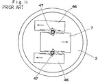
- the arrangement of Fig.10 permits adjustment of tool radial position without stopping revolution of workspindle 1, accordingly improving the working efficiency. Deviation of the center of gravity of the rotating mass apart from the rotary axis of spindle 1 increases with displacement of slide 7 and tool C.
- a balancer attachment for the spindle of a machining apparatus comprises a rotary disk to be fixed to the end of the spindle of the machining apparatus, a traverse slide fixed to said rotary disk to be movable in diametrically opposite directions from the central axis of the spindle, said traverse slide having a longitudinal slot made centrally in its rear surface, and a pair of primary balancers each comprising a weight and a shank integrally connected thereto, and each being rotatably fixed to said disk about an intermediate pivot of the shank with the end of each shank slidably fitted in the longitudinal slot in the rear surface of the traverse slide.
- the present invention provides a balancer attachment for the spindle of a machining apparatus which attachment has balancing means of relatively small size, and is capable of preventing undesired displacement of its tool slide due to the centrifugal force generated during rotation.
- said weight of each primary balancer has guide means; said disk has an annular flange integrally connected to its circumference and extending radially inside; and said balancer attachment further comprises two seondary balancers each comprising a weight slidably fixed to the edge of said annular flange and having a guide slot to slidably accept the guide means of said weight of each primary balancer.
- a balancer attachment for the spindle of a machining apparatus is provided which attachment is capable of reducing an appreciable imbalance which will be caused by an associated tool when displaced to a remote position from the center of revolution, thereby assuring the machining accuracy even in this case.
- the centrifugal force of the traverse slide increases linearly with the increase of the distance which it traverses on the rotary disk. As the traversing distance of the slide increases, its centrifugal force will be larger than the resultant force of the centrifugal forces of the primary balancers, thus causing imbalance in the rotating mass so far as only the primary balancers are relied on.
- the radius from the center of gravity of the weight of the primary balancer to the pivot of the primary balancer is smaller than the radius from the center of gravity of the weight of the primary balancer to the center of the disk.
- Figs.1 and 2 show a balancer attachment for the spindle of a machining apparatus according to a first embodiment of the present invention.
- rotary disk 2 is fixed to the end of hollow cylindrical spindle 1 perpendicular thereto.
- a pair of parallel holder rods (not shown ) are provided on the front of rotary disk 2.
- Traverse slide 7 consists of an integration of tool holder cubic 5 and flat base plate 6, and traverse slide 7 is slidably fitted in between the parallel rods. Push plates 3, 3 are applied to the parallel rods to permit slide 7 to traverse freely on rotary disk 2.
- Tool drive shaft 10 is in inner space 9 of spindle 1.
- Drive means for driving spindle 1 and tool drive shaft 10 are equipped with transmission to permit spindle 1 and tool drive shaft 10 to rotate normally at same speed in same direction, and permit tool drive shaft 10 to rotate at speed which is different from the rotating speed of spindle 1 only when traverse slide 7 is desired to traverse.
- Female nut 11 is fixed to the rear surface of traverse slide 7 as seen leftwards in Figs.1 and 2, and male bolt 12 is inserted in female nut 11.
- Male bolt 12 has conical gear wheel 13 integrally connected to the intermediate portion thereof.
- tool drive shaft 10 has conical gear wheel 14 integrally connected to the end thereof.
- Conical gear wheel 13 is mated with conical gear wheel 14.
- Rotary disk 2 is provided with two parallel rods 4, 4, which passes through traverse slide 7. Each parallel rod has spring means (not shown ) to urge traverse slide 7 rightwards in the drawings all the time.
- Each of a pair of primary balancers A comprises weight 16 and shank 15 integrally connected thereto.
- Each primary balancer A is rotatably fixed to disk 2 about the intermediate point of shank 5 by pin 15a.
- Traverse slide 7 has longitudinal slot 24 made centrally in its rear surface. The end of each shank 15 is slidably fitted in longitudinal slot 24 by inserting square head 25 of associated square-headed pin 17 therein.
- rotary disk 2 is enclosed in casing 8 to prevent invasion of foreign substances.
- each side guide projection 34 has two slant sections 35a and 35b at its diagonally opposite corners, thus leaving a staggered-rectangular section on its top surface.
- Center guide projection 32 has a notched cylindrical rod 37 rotatably fitted in hole 36.
- Notched cylindrical rod 37 has vertical flat plane 37a and toothed circumference 38 in the form of pinion.
- This pinion 38 is mated with parallel racks 39a and 39b, which are slidably fitted in through holes made in tool holder cubic 5.
- Rack 39a has two notches 76 and 77 made on its rear side, and these notches 76 and 77 are adapted to accept spring-biased catch bolt 78 when rack 39a is raised or lowered to predetermined vertical positions in which notched cylindrical rod 37 is rotated to have its vertical flat plane 37a flush with the side of center guide projection 32 or its round circumference projecting from the side of center guide projection 32.
- adapter 31 As for adapter 31 to be attached to tool holder cubic 5 it has a center slot 40 to accept center guide projection 32 of tool holder cubic 5, "V"-shaped projections 41 are adapted to fit in parallel slots 33 of tool holder cubic 5 and two staggered-rectangular sections 42 are adapted to fit on the staggered-rectangular sections of opposite side guide projectionsw 34 of tool holder cubic 5. Each staggered-rectangular section 42 has slant sections 43a and 43b at its diagonally opposite corners.Semicircular recess 44 is made in left "V"-shaped project ion 41 to allow notched cylindrical rod 37 to enter when it turns.
- adapter 31 is allowed to fit and descend on the surface of tool holder cubic 5, and consequently adapter 31 is nested with tool holder cubic 5 with "V"-shaped projections 41 inserted in parallel slots 33.
- each slant section 43a of adapter 31 rides on the staggered-rectangular surface 34 of each side wall of tool holder cubic 5 to assist adapter 31 in aligning with tool holder cubic 5 so that "V"-shaped projections 41 may be fitted exactly in parallel slots 33 of tool holder cubic 5.
- rack 39b is pushed down to rotate pinion 38 until notched cylindrical rod 37 is fitted in semicircular recess 44 of "V"-shaped projection 41, thereby permitting adapter 31 to be mated with tool holder cubic 5.
- Adapter 31 carries a cutting tool C, and traverse slider 7 carries adapter 31.
- machining can be performed by rotating spindle 1, which is connected to traverse slider 7.
- Fig.3 shows the position of rotary disk 2 in which traverse slide 7 is not displaced.
- the center of gravity of traverse slide 7 and cutting tool C is on the center axis of spindle 1.
- the center of gravity of each member on rotary disk 2 ( or the resultant centrifugal force of traverse slide 7 and primary balancers A ) is on the center axis of spindle 1.Cutting tool C will rotate about the cener axis of spindle 1.
- Fig.4 shows the position in which traverse slide 7 is displaced rightwards. As traverse slide 7 is displaced rightwards, the square heads of guide pins 17 of primary balancers A move apart from each other in guide slot 24 of traverse slide 7, thereby causing weights 16 of primary balancers A to move towards each other in such directions that equilibrium may be maintained on rotary disk 2.
- traverse slide 7 is urged rightwards by springs (not shown ) fitted on guide shafts 4, and therefore no error will be caused in traversing distance by the play between nut 11 and bolt 12.
- the balancer attachment described so far may be equipped with secondary balancers according to the present invention, as will be described below.
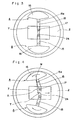
- FIGs.5 to 7 show a balancer attachment equipped with secondary balancers according to the second embodiment of the present invention.
- annular flange 23 is integrally connected to the circumference of rotary disk 2 to extend radially inside.
- Two sector weights 19 sandwich annular flange 23, and the lower sides of sector weights 19 are connected by the shafts of two rolls 21.
- Front sector weight 19 has "V"-shaped groove 22, which is composed of two circular arcs combined generally in the form of the letter "V".
- one secondary balancer is provided, and it can travel freely along the inner circular edge of frange 23 with the aid of its rolls 21.
- another secondary balancer B is provided.
- Weight 16 of each primary balancer A has guide pins 18 on its opposite ends.
- Each secondary balancer B is connected to associated primary balancer A with one or both of guide pins 18 of weight 16 in "V"-shaped groove 22 of sector weight 19.
- Fig.6 shows the condition in which traverse slide 7 is not shifted, and in this condition the center of gravity of traverse slide 7 and associated cutting tool C is on the center axis of spindle 1.
- primary and secondary balancers A and B are put in neutral position in rotary disk 2, and the center of gravity of each unit on rotary disk 2 ( i.e. resultant centrifugal force of traverse slide 7, primary and secondary balancers A and B ) is on the center axis of spindle 1. Therefore, cutting tool C rotates about the central axis of spindle 1.
- the centrifugal force of traverse slide 7, which is given by S m r ⁇ 2, will increase with traversing distance T of traverse slide 7.
- the rotating radius of primary balancer A distance from pivot 15a to the center of gravity W of primary balancer A ) is smaller than the rotating radius r1 of the center of gravity W of weight 16.
- the resultant centrifugal force of upper and lower primary balancers A will not vary in proportion to the traversing distance T of traverse slide 7.
- Secondary balancers B will slide along the inner circumference edge of frange 23 of rotary disk 2 to come closer to each other, following the circular arc at a constant distance r2 from spindle 1. Therefore, the resultant centrifugal force of upper and lower secondary balancers B will remain constant, changing only in direction.
- the resultant centrifugal force of primary and secondary balancers A and B can balance with the centrifugal force of traverse slide 7, provided that all related factors are determined appropriately for the purpose.
- primary balancers A will take major part in balancing with traverse slide 7 whereas while traverse slide 7 is traversing a relatively long distance, secondary balancers B will take major part in balancing with traverse slide 7.
- the resultant centrifugal force of primary and secondary balancers A and B will change in the same way as the centrifugal force of traverse slide 7 in magnitude, but in opposite directions, thus compensating for imbalance which otherwise, would be caused by displacement of traverse slide 7 in rotary disk 2.
- Secondary balancers B will be pushed against frange 23 by its centrifugal force, thereby preventing primary balancers A from returning to neutral positions via pins 18 to keep primary balancers A inclined at correct angles.
- a balancer attachment uses two primary balancers which are designed to cause rotary movements rather than linear movements in response to the linear displacement of the traverse slide, thus permitting substantial reduction of the size of balancer attachment, still assuring reduction of the imbalance caused by displacement of an associated tool away from the spindle axis of a machining apparatus in rotary disk 2.
- Two secondary balancers used in combination with the primary balancers have the effect of reducing an appreciable imbalnce which cannot be reduced only by the primary balancers. Thanks to the improvement in balancing condition attained by the balancer attachment, even if rotating-and-cutting operation is performed at an increased rate ranging from 1000 to 1500 revolutions per minute, the accuracy of spindle revolution will not be reduced, and the durability of the machining apparatus will not be adversely affected.
- the primary and secondary balancers are coupled in simple mechanical connection.
Landscapes
- Engineering & Computer Science (AREA)
- Mechanical Engineering (AREA)
- Turning (AREA)
- Auxiliary Devices For Machine Tools (AREA)
- Machine Tool Units (AREA)
Applications Claiming Priority (2)
| Application Number | Priority Date | Filing Date | Title |
|---|---|---|---|
| JP2336827A JPH04201155A (ja) | 1990-11-30 | 1990-11-30 | 工作機械主軸のバランス装置 |
| JP336827/90 | 1990-11-30 |
Publications (1)
| Publication Number | Publication Date |
|---|---|
| EP0488774A1 true EP0488774A1 (de) | 1992-06-03 |
Family
ID=18303037
Family Applications (1)
| Application Number | Title | Priority Date | Filing Date |
|---|---|---|---|
| EP91311096A Ceased EP0488774A1 (de) | 1990-11-30 | 1991-11-29 | Auswuchtung eines Werkzeughalters |
Country Status (4)
| Country | Link |
|---|---|
| US (1) | US5154554A (de) |
| EP (1) | EP0488774A1 (de) |
| JP (1) | JPH04201155A (de) |
| KR (1) | KR940002681B1 (de) |
Cited By (3)
| Publication number | Priority date | Publication date | Assignee | Title |
|---|---|---|---|---|
| WO2006029682A1 (de) * | 2004-09-14 | 2006-03-23 | Komet Group Holding Gmbh | Werkzeugkopf für den einsatz in werkzeugmaschinen mit unwuchttilgung |
| DE102008030925A1 (de) * | 2008-07-02 | 2010-01-21 | Franz Kessler Gmbh | Werkzeugmaschinenkomponente, insbesondere Drehtisch für Drehfräsbearbeitung und Auswuchtverfahren |
| CN103949697A (zh) * | 2014-04-16 | 2014-07-30 | 于法周 | 一种钻床的万用底座 |
Families Citing this family (17)
| Publication number | Priority date | Publication date | Assignee | Title |
|---|---|---|---|---|
| US5263995A (en) * | 1993-01-27 | 1993-11-23 | Kennametal Inc. | Apparatus and method for balancing a rotary tool assembly |
| KR100274788B1 (ko) * | 1998-04-10 | 2000-12-15 | 권영두 | Cnc 선반의주축 소재착탈 장치 |
| US6530727B2 (en) * | 1998-04-13 | 2003-03-11 | Harmand Family Limited Partnership | Contour machining head |
| JP3988370B2 (ja) * | 2000-09-08 | 2007-10-10 | 日立工機株式会社 | セーバソー |
| US6419427B1 (en) * | 1999-11-09 | 2002-07-16 | Paul S Galamba | Adjustable rotary tool providing a counter balanced system |
| JP4917197B2 (ja) * | 2000-02-18 | 2012-04-18 | 株式会社岡本工作機械製作所 | 研削装置の回転軸のアンバランス補正方法 |
| US6606922B2 (en) * | 2000-04-28 | 2003-08-19 | Schmitt Measurement Systems, Inc. | Rotational imbalance compensator |
| JP3768799B2 (ja) * | 2000-10-30 | 2006-04-19 | キヤノン株式会社 | 置換脂肪酸エステル化物を原料とするポリヒドロキシアルカノエートの製造方法 |
| US6471453B1 (en) | 2001-05-25 | 2002-10-29 | Kennametal Inc. | Balancing assembly for a rotating member |
| JP2003145383A (ja) * | 2001-11-15 | 2003-05-20 | Mitsubishi Heavy Ind Ltd | 工作機械 |
| JP2004174676A (ja) * | 2002-11-28 | 2004-06-24 | Toyo Advanced Technologies Co Ltd | 工作物の加工方法および工作機械の主軸 |
| DE102004036394A1 (de) * | 2004-07-27 | 2006-03-23 | Franz Haimer Maschinenbau Kg | Wuchtring und Verfahren zum Auswuchten eines rotierenden Bauteils |
| CN100436050C (zh) * | 2007-06-07 | 2008-11-26 | 浙江大学 | 全自动平衡机切削点自动定位装置 |
| DE102011111549A1 (de) * | 2011-08-24 | 2013-02-28 | MAPAL Fabrik für Präzisionswerkzeuge Dr. Kress KG | Werkzeug zum Bearbeiten von Werkstücken |
| US9486862B1 (en) | 2014-07-25 | 2016-11-08 | Anthony P. LaMarca, Sr. | Fly cutter cutting tool |
| USD765747S1 (en) | 2015-05-16 | 2016-09-06 | Anthony P. LaMarca, Sr. | Fly cutter cutting tool |
| US10124453B2 (en) * | 2016-11-15 | 2018-11-13 | Tsung-Hua Wong | Headstock structure of computer numerical control milling and boring machine tool |
Citations (3)
| Publication number | Priority date | Publication date | Assignee | Title |
|---|---|---|---|---|
| DE3633320A1 (de) * | 1985-12-11 | 1987-06-19 | Schmalkalden Werkzeug | Rotierendes zerspanungswerkzeug mit einstellbaren unwuchtausgleichelementen |
| DE3918118A1 (de) * | 1989-06-02 | 1990-12-06 | Gte Valenite Corp | Plandrehkopf mit massenausgleich |
| DE3926026A1 (de) * | 1989-08-07 | 1991-02-14 | Kuehn Praezisionswerkzeug | Werkzeugkopf, insbesondere feinbohrkopf |
Family Cites Families (3)
| Publication number | Priority date | Publication date | Assignee | Title |
|---|---|---|---|---|
| SU498431A2 (ru) * | 1974-04-23 | 1976-01-05 | Предприятие По Ремонту Электроэнергетического Оборудования Эрп "Харьковэнерго" | Автоматическа полумуфта |
| CH663739A5 (de) * | 1984-03-21 | 1988-01-15 | Urma Werkzeug Maschf | Vorrichtung an einem durchmesserverstellbaren ausdrehwerkzeug mit schneidplattenhalter. |
| US5074723A (en) * | 1989-04-13 | 1991-12-24 | Kennametal Inc. | Method and apparatus for balancing a rotary tool assembly |
-
1990
- 1990-11-30 JP JP2336827A patent/JPH04201155A/ja active Pending
-
1991
- 1991-06-28 KR KR1019910010981A patent/KR940002681B1/ko not_active Expired - Lifetime
- 1991-11-22 US US07/796,011 patent/US5154554A/en not_active Expired - Fee Related
- 1991-11-29 EP EP91311096A patent/EP0488774A1/de not_active Ceased
Patent Citations (3)
| Publication number | Priority date | Publication date | Assignee | Title |
|---|---|---|---|---|
| DE3633320A1 (de) * | 1985-12-11 | 1987-06-19 | Schmalkalden Werkzeug | Rotierendes zerspanungswerkzeug mit einstellbaren unwuchtausgleichelementen |
| DE3918118A1 (de) * | 1989-06-02 | 1990-12-06 | Gte Valenite Corp | Plandrehkopf mit massenausgleich |
| DE3926026A1 (de) * | 1989-08-07 | 1991-02-14 | Kuehn Praezisionswerkzeug | Werkzeugkopf, insbesondere feinbohrkopf |
Cited By (6)
| Publication number | Priority date | Publication date | Assignee | Title |
|---|---|---|---|---|
| WO2006029682A1 (de) * | 2004-09-14 | 2006-03-23 | Komet Group Holding Gmbh | Werkzeugkopf für den einsatz in werkzeugmaschinen mit unwuchttilgung |
| RU2353479C2 (ru) * | 2004-09-14 | 2009-04-27 | Комет Груп Холдинг Гмбх | Инструментальная головка для применения в станках с компенсацией дисбаланса (варианты) |
| US7871226B2 (en) | 2004-09-14 | 2011-01-18 | Komet Group Gmbh | Tool head for machine-tools with unbalance damping |
| CN101018634B (zh) * | 2004-09-14 | 2011-03-30 | 彗星集团有限公司 | 在机床中使用的消除不平衡的组合式刀盘 |
| DE102008030925A1 (de) * | 2008-07-02 | 2010-01-21 | Franz Kessler Gmbh | Werkzeugmaschinenkomponente, insbesondere Drehtisch für Drehfräsbearbeitung und Auswuchtverfahren |
| CN103949697A (zh) * | 2014-04-16 | 2014-07-30 | 于法周 | 一种钻床的万用底座 |
Also Published As
| Publication number | Publication date |
|---|---|
| US5154554A (en) | 1992-10-13 |
| KR940002681B1 (ko) | 1994-03-30 |
| KR920009509A (ko) | 1992-06-25 |
| JPH04201155A (ja) | 1992-07-22 |
Similar Documents
| Publication | Publication Date | Title |
|---|---|---|
| US5154554A (en) | Balancer attachment of the main spindle of a machining apparatus | |
| US4067251A (en) | Facing and inside-turning head | |
| CN102990101A (zh) | 用于镗孔刀具的自动平衡系统及结合了该自动平衡系统的镗孔刀具 | |
| US4891916A (en) | Oscillatory or translational table for machine tools | |
| CN110227946A (zh) | 六轴镗铣加工机床 | |
| SE430227B (sv) | Forfarande och stalhallare for bearbetning av rotationskroppar medelst rotationsstal i en verktygsmaskin | |
| US5988240A (en) | Lamella groove milling tool | |
| US7871226B2 (en) | Tool head for machine-tools with unbalance damping | |
| US4815347A (en) | Lathe attachment with axially movable chuck | |
| US5174697A (en) | Tool mount for a machining apparatus | |
| US4999894A (en) | 5th axis machining center fixture | |
| JPH09309010A (ja) | 穿孔工具 | |
| US4411177A (en) | Numerical control surfacing plate | |
| US4890419A (en) | Device for grinding cutting tools having straight and spiral grooves | |
| EP0340281B1 (de) | Orbitaler pisch für werkzeugmaschinen | |
| US4363193A (en) | Universal grinding machine | |
| US5658104A (en) | Method and system for the manufacture of CO2 powered dragster | |
| EP2822721B1 (de) | Adapter | |
| KR0131604Y1 (ko) | 편심가공용 연동척 | |
| US3785245A (en) | Multi-curve generator | |
| JPS6140440Y2 (de) | ||
| JPH0112935Y2 (de) | ||
| US5022665A (en) | Workpiece support tool | |
| US5101700A (en) | Rotatable tool head | |
| JPH044093B2 (de) |
Legal Events
| Date | Code | Title | Description |
|---|---|---|---|
| PUAI | Public reference made under article 153(3) epc to a published international application that has entered the european phase |
Free format text: ORIGINAL CODE: 0009012 |
|
| AK | Designated contracting states |
Kind code of ref document: A1 Designated state(s): CH DE FR GB IT LI |
|
| 17P | Request for examination filed |
Effective date: 19921118 |
|
| 17Q | First examination report despatched |
Effective date: 19940608 |
|
| STAA | Information on the status of an ep patent application or granted ep patent |
Free format text: STATUS: THE APPLICATION HAS BEEN REFUSED |
|
| 18R | Application refused |
Effective date: 19941128 |