EP0488828A2 - Steuervorrichtung für einen sich selbständig bewegenden Körper und Verfahren zur Auswertung der Daten davon - Google Patents
Steuervorrichtung für einen sich selbständig bewegenden Körper und Verfahren zur Auswertung der Daten davon Download PDFInfo
- Publication number
- EP0488828A2 EP0488828A2 EP91311210A EP91311210A EP0488828A2 EP 0488828 A2 EP0488828 A2 EP 0488828A2 EP 91311210 A EP91311210 A EP 91311210A EP 91311210 A EP91311210 A EP 91311210A EP 0488828 A2 EP0488828 A2 EP 0488828A2
- Authority
- EP
- European Patent Office
- Prior art keywords
- data
- road
- processing
- moving road
- section
- Prior art date
- Legal status (The legal status is an assumption and is not a legal conclusion. Google has not performed a legal analysis and makes no representation as to the accuracy of the status listed.)
- Granted
Links
Images






Classifications
-
- G—PHYSICS
- G05—CONTROLLING; REGULATING
- G05D—SYSTEMS FOR CONTROLLING OR REGULATING NON-ELECTRIC VARIABLES
- G05D1/00—Control of position, course, altitude or attitude of land, water, air or space vehicles, e.g. using automatic pilots
- G05D1/02—Control of position or course in two dimensions
- G05D1/021—Control of position or course in two dimensions specially adapted to land vehicles
- G05D1/0231—Control of position or course in two dimensions specially adapted to land vehicles using optical position detecting means
- G05D1/0246—Control of position or course in two dimensions specially adapted to land vehicles using optical position detecting means using a video camera in combination with image processing means
-
- B—PERFORMING OPERATIONS; TRANSPORTING
- B60—VEHICLES IN GENERAL
- B60W—CONJOINT CONTROL OF VEHICLE SUB-UNITS OF DIFFERENT TYPE OR DIFFERENT FUNCTION; CONTROL SYSTEMS SPECIALLY ADAPTED FOR HYBRID VEHICLES; ROAD VEHICLE DRIVE CONTROL SYSTEMS FOR PURPOSES NOT RELATED TO THE CONTROL OF A PARTICULAR SUB-UNIT
- B60W60/00—Drive control systems specially adapted for autonomous road vehicles
- B60W60/001—Planning or execution of driving tasks
-
- G—PHYSICS
- G05—CONTROLLING; REGULATING
- G05D—SYSTEMS FOR CONTROLLING OR REGULATING NON-ELECTRIC VARIABLES
- G05D1/00—Control of position, course, altitude or attitude of land, water, air or space vehicles, e.g. using automatic pilots
- G05D1/02—Control of position or course in two dimensions
- G05D1/021—Control of position or course in two dimensions specially adapted to land vehicles
- G05D1/0255—Control of position or course in two dimensions specially adapted to land vehicles using acoustic signals, e.g. ultra-sonic singals
-
- G—PHYSICS
- G05—CONTROLLING; REGULATING
- G05D—SYSTEMS FOR CONTROLLING OR REGULATING NON-ELECTRIC VARIABLES
- G05D1/00—Control of position, course, altitude or attitude of land, water, air or space vehicles, e.g. using automatic pilots
- G05D1/02—Control of position or course in two dimensions
- G05D1/021—Control of position or course in two dimensions specially adapted to land vehicles
- G05D1/0268—Control of position or course in two dimensions specially adapted to land vehicles using internal positioning means
- G05D1/0272—Control of position or course in two dimensions specially adapted to land vehicles using internal positioning means comprising means for registering the travel distance, e.g. revolutions of wheels
-
- G—PHYSICS
- G06—COMPUTING OR CALCULATING; COUNTING
- G06V—IMAGE OR VIDEO RECOGNITION OR UNDERSTANDING
- G06V10/00—Arrangements for image or video recognition or understanding
- G06V10/40—Extraction of image or video features
- G06V10/44—Local feature extraction by analysis of parts of the pattern, e.g. by detecting edges, contours, loops, corners, strokes or intersections; Connectivity analysis, e.g. of connected components
- G06V10/457—Local feature extraction by analysis of parts of the pattern, e.g. by detecting edges, contours, loops, corners, strokes or intersections; Connectivity analysis, e.g. of connected components by analysing connectivity, e.g. edge linking, connected component analysis or slices
-
- G—PHYSICS
- G06—COMPUTING OR CALCULATING; COUNTING
- G06V—IMAGE OR VIDEO RECOGNITION OR UNDERSTANDING
- G06V20/00—Scenes; Scene-specific elements
- G06V20/50—Context or environment of the image
- G06V20/56—Context or environment of the image exterior to a vehicle by using sensors mounted on the vehicle
- G06V20/588—Recognition of the road, e.g. of lane markings; Recognition of the vehicle driving pattern in relation to the road
-
- B—PERFORMING OPERATIONS; TRANSPORTING
- B60—VEHICLES IN GENERAL
- B60W—CONJOINT CONTROL OF VEHICLE SUB-UNITS OF DIFFERENT TYPE OR DIFFERENT FUNCTION; CONTROL SYSTEMS SPECIALLY ADAPTED FOR HYBRID VEHICLES; ROAD VEHICLE DRIVE CONTROL SYSTEMS FOR PURPOSES NOT RELATED TO THE CONTROL OF A PARTICULAR SUB-UNIT
- B60W2420/00—Indexing codes relating to the type of sensors based on the principle of their operation
- B60W2420/40—Photo, light or radio wave sensitive means, e.g. infrared sensors
- B60W2420/403—Image sensing, e.g. optical camera
-
- B—PERFORMING OPERATIONS; TRANSPORTING
- B60—VEHICLES IN GENERAL
- B60W—CONJOINT CONTROL OF VEHICLE SUB-UNITS OF DIFFERENT TYPE OR DIFFERENT FUNCTION; CONTROL SYSTEMS SPECIALLY ADAPTED FOR HYBRID VEHICLES; ROAD VEHICLE DRIVE CONTROL SYSTEMS FOR PURPOSES NOT RELATED TO THE CONTROL OF A PARTICULAR SUB-UNIT
- B60W2552/00—Input parameters relating to infrastructure
- B60W2552/53—Road markings, e.g. lane marker or crosswalk
-
- G—PHYSICS
- G05—CONTROLLING; REGULATING
- G05D—SYSTEMS FOR CONTROLLING OR REGULATING NON-ELECTRIC VARIABLES
- G05D1/00—Control of position, course, altitude or attitude of land, water, air or space vehicles, e.g. using automatic pilots
- G05D1/02—Control of position or course in two dimensions
- G05D1/021—Control of position or course in two dimensions specially adapted to land vehicles
- G05D1/0231—Control of position or course in two dimensions specially adapted to land vehicles using optical position detecting means
- G05D1/0242—Control of position or course in two dimensions specially adapted to land vehicles using optical position detecting means using non-visible light signals, e.g. IR or UV signals
-
- G—PHYSICS
- G05—CONTROLLING; REGULATING
- G05D—SYSTEMS FOR CONTROLLING OR REGULATING NON-ELECTRIC VARIABLES
- G05D1/00—Control of position, course, altitude or attitude of land, water, air or space vehicles, e.g. using automatic pilots
- G05D1/02—Control of position or course in two dimensions
- G05D1/021—Control of position or course in two dimensions specially adapted to land vehicles
- G05D1/0231—Control of position or course in two dimensions specially adapted to land vehicles using optical position detecting means
- G05D1/0246—Control of position or course in two dimensions specially adapted to land vehicles using optical position detecting means using a video camera in combination with image processing means
- G05D1/0251—Control of position or course in two dimensions specially adapted to land vehicles using optical position detecting means using a video camera in combination with image processing means extracting 3D information from a plurality of images taken from different locations, e.g. stereo vision
-
- G—PHYSICS
- G05—CONTROLLING; REGULATING
- G05D—SYSTEMS FOR CONTROLLING OR REGULATING NON-ELECTRIC VARIABLES
- G05D1/00—Control of position, course, altitude or attitude of land, water, air or space vehicles, e.g. using automatic pilots
- G05D1/02—Control of position or course in two dimensions
- G05D1/021—Control of position or course in two dimensions specially adapted to land vehicles
- G05D1/0268—Control of position or course in two dimensions specially adapted to land vehicles using internal positioning means
- G05D1/0274—Control of position or course in two dimensions specially adapted to land vehicles using internal positioning means using mapping information stored in a memory device
Definitions
- the present invention relates to a control device to be used for running control of an autonomously moving body such as an autonomously running vehicle or robot and a method to evaluate the data of the moving body obtained in an image processing by the control device.
- Running control of an autonomously running vehicle has been conventionally conducted by continuously picking up images of a front view by a camera mounted on the vehicle body; and a running course is recognized according to the inputted image.
- the reliability of techniquesto recognize a running course only by image data obtained from one camera is rather low. Therefore, in order to improve the reliability of obtained road data, attempts have been made to stably control autonomous running by inputting road images from a plurality of cameras and detecting running conditions by a plurality of sensors.
- An object of the present invention is to increase the reliability of the data obtained by a control device and to provide an evaluation method therefor which is used to evaluate data under the same time.
- the present invention has been achieved in order to solve the aforementioned problems.
- the present invention provides a control device of an autonomously moving body comprising: at least one image pickup unit which picks up the image of a moving road of an autonomously moving body; an image processing unit which processes a plurality of image data outputted from the image pickup unit, and detects and outputs the condition of said moving road, or an outside information obtaining unit which obtains information other than image; a storage means which stores data outputted from said image processing unit or said outside information obtaining means; a data control section which corrects said data stored in said storage means to data of an arbitrary time and position; a data evaluating section which integrates a plurality of data outputted from said data control section into one moving road data; and a control section which controls the movement of an autonomously moving body according to the moving read data outputted from said data evaluating section.
- An evaluation method has been achieved in order to solve the above described conventional problems, and provides an evaluation method for a vehicle moving road, characterized in that: a sequence of points data extracted from the vehicle moving road data, the image of which was taken by an image pickup device, is inputted by being corrected to data of the same time and said sequence of points data is held structured to the level of line and point, and the conditions of the line and point composing the vehicle moving road are described as a model; likeness of the aforementioned sequence of points data to a vehicle moving road is judged by a predetermined rule in which a model is used as a verification reference; and the aforementioned inputted sequence of points data is transformed into one appropriate datum of a vehicle moving road according to the result of judgment.
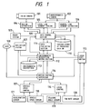
- This unit comprises an image processing section, a navigation system section, a data control section, a data evaluating section, an environmental description making section, a motion control supervisor, a locus estimating section, and a driving control section.
- the image processing section includes at least one image pickup device, an outside information obtaining means to obtain outside information other than images, and an image processing device in which a plurality of image processing techniques are used.
- a plurality of standard focal distance image pickup devices, telephoto image pickup devices, color image pickup devices, infrared image pickup devices, or super sensitive image pickup devices are used to compose at least one image pickup device, however in this embodiment, a color camera 101 and a monochromatic camera 102 are used for the image pickup device.
- a radar, an ultrasonic sensor and the like are used for the outside information obtaining means to obtain outside information other than images however in this embodiment, a radar system 103 is utilized. This radar system is used to detect an obstacle which is located in a far front position of a driving vehicle, and information about the number and position of the obstacle can be obtained by the radar system. The obtained obstacle information is outputted into the data control section 109.
- image processing in the image processing device is conducted for the purpose of extracting road data.
- the image processing means comprises a region extracting means, a local line segment tracing means, a general line segment extracting means, a stereoscopic means, and a moving image processing means.
- image information inputted from the color camera 101 is processed using the region extracting means 104 and a road region is extracted based on color images.
- the extracted road region boundary data and positional data are outputted to the data control section 109.
- Image information inputted from the monochrome camera 102 is processed by the local line segment tracing means 105 and the general line segment extracting means 106.
- the local line segment tracing means 105 extracts small area of road edges which have been obtained by processing a monochromatic image.
- the extracted local line segment data is outputted into the data control section 109.
- the general line segment extracting means 106 approximates and estimates generally the road edge to obtain a guide line.
- the general main line segment obtained is outputted to the data control section 109.
- the navigation system 107 is provided with an interface to communicate with a user (human being) 108, with the object to make and instruct a general running schedule. At present, this general driving schedule such as destination, etc., is inputted into the navigation system 107 by the user 108. According to the map information stored inside, the navigation system 107 outputs global map information such as a general route and its peripheral map information, a route instruction, and a legal speed limit, to the environmental description making section 112 and motion control supervisor 114. Also the user 108 can command the motion control supervisor 114 to change over the driving mode.
- Various image processing data are inputted into the data control section 109 from the image processing device, and information concerning obstacle is inputted from the radar system 103.
- Environmental description data at an arbitrary time is inputted into the data control section 109 from the environmental description making section 112.
- the data control section 109 stores these various inputted data in a data base (DB) 110 to control data base, that is to control the result of image processing and the time of obstacle information detected by the radar.
- DB data base
- Road edge data on an image pickup surface which has been obtained by an image pickup device installed diagonally with regard to a road surface and processed by the image processing device, is projectively transformed and projected on a two dimensional road surface.
- the coordinate of data is transformed into a coordinate system of a past arbitrary time according to the time accompanying the data and an estimated locus table calculated by the locus estimating section 115.
- a candidate region is instructed to the region extracting means 104 so that a search starting point and searching direction are instructed to the local line segment tracing means 105 and a candidate line segment is instructed to the general line segment extracting means 106.
- Image processing data with time and coordinate being matched is inputted into the data evaluating section 111 from the data controlling section 109, and environmental description data at an arbitrary time is inputted into the data evaluating section 111 from the environmental description making section 112.
- Incorrect data are eliminated by judging a plurality of two dimensional road data, transformed in same time coordinates, with respect to their conformity with the road model and compatibility between each road data.
- a plurality of data which have been judged to be appropriate as road data are integrated into one datum.
- Integrated road data which are the result of data evaluation are outputted into the data control section 109 and the environment describing section 112.
- the environmental description making section 112 integrally holds results of recognizing obstacle information or the like to describe the environment in which the vehicle is situated. That is to say, the road data inputted from the data evaluating section 111 is expressed by means of a vector, and held and controlled as the environmental data base 113. Also, inputted road data is superimposed on the environmental description being already held, to determine and eliminate an attribute of each line segment in the data according to connecting relation with past data and relative position etc. with regard to the vehicle.
- the motion control supervisor 114 makes a movement plan of the autonomously driving vehicle and instructs its movement. That is, by a man-machine interface between the motion control supervisor 114 and the driver (the user 108), changeover is conducted between automatic and manual driving, and between start and stop of driving. Judgment of necessity to evade an obstacle and select a traffic lane is conducted according to the environmental description data sent from the environmental description making section 112, guiding information from the navigation system 107, movement amount of the vehicle from the locus estimating section 115, and vehicle speed information sent from the vehicle speed control section 117, to prepare a route plan.
- a speed plan composed of a driving speed and a specified distance at which the vehicle speed reaches said driving speed is made according to the visual field distance of an image, the vehicle speed, the time needed for recognizing the environment, and the legal speed obtained from the navigation system 107. Further, on the basis of the route plan and the speed plan, movement is instructed by matching control sections (the locus control section 116 and the vehicle speed control section 117). This movement plan is outputted into the environmental description making section 112. The instructed route is outputted to the locus control section 116, and the instructed speed is outputted to the vehicle speed control section 117.
- a locus of the vehicle body on a coordinate is calculated from the movement of the vehicle body.
- the locus control section 116 functions as a reference clock of the system. According to the calculated result of the locus, the movement amount of the vehicle is found, which is outputted to the data control section 109, the environmental description making section 112, and the motion control supervisor 114.
- the driving control section is composed of the locus control section 116 and the vehicle speed control section 117.
- To the locus control section 116 sensor information is inputted from the vehicle sensor 118, the steering angle sensor 119, and the yaw rate sensor 120.
- This locus control section 116 is provided with a steering angle control means which can control at least one of the front and rear wheel.
- To the vehicle speed control section 117 sensor information sent from the vehicle speed sensor 118 and an acceleration sensor 121 is inputted.
- This vehicle speed control section 117 is provided with a means to control engine output and brake force by adjusting opening of an accelerator and brake pressure, and vehicle speed information is outputted to the motion control supervisor 114.
- a color camera 101 and monochromatic camera 102 will be explained. Since an image pickup device has to be installed in a vehicle, it is desirable that one set of camera is shared among a plurality of processings. However, since various natural images are processed and further the vehicle speed is varied, it is preferable that a plurality of image input means are provided to suit various circumstances.
- the image input means which is suitable for various circumstances is for example, when a telephotographic camera and a wide angle camera are utilized, a visual field can be covered in such a manner that both cameras compensate with each other.
- an infrared camera is suitable since it can detect the difference in temperature between a road and a road shoulder, and being further hardly affected by light of a vehicle running on the opposite lane.
- a stereoscopic vision is used to find the distance from a foregoing vehicle, more than two cameras are necessary. Therefore, in this embodiment, two kinds of image pickup devices (the color camera 101 and the monochromatic camera 102) are utilized, and further a radar system 103 is employed to secure information appropriate for various circumstances.
- the region extracting means 104 will be explained.
- extracting a line segment becomes extremely unstable.
- extracting a region by color characteristics is effective (Lightness I, Saturation S, Hue H). Therefore, in this embodiment, a color camera 101 is adopted as one of the image pickup devices so that the road region is extracted by the road extracting means 104 in accordance with the characteristic of colors.
- the extraction of road region described above is conducted on the assumption that the area immediately in front of the vehicle is a road region, and a portion with color characteristic similar to that of the road region is extracted. It is also possible to extract a road region at night by a technique essentially the same as the aforementioned extracting process, utilizing an infrared camera to judge temperature of a road from an infrared image at night.
- the general line segment extracting means 106 will be explained as follows. According to this means, a wide range in an image can be processed all at once in the case where the road structure is simple, for example in the case of a highway in which the road is straight. For example, a region in which a road is assumed to exist from the setting angle of a TV camera, Hough-Transformation which is an excellent straight line detection means is applied. Even when the region is not wide enough to cover the entire road, the boundary can be extracted if the road is straight, and as it suffices to apply Hough-Transformation only once, the boundary can be extracted with extremely high speed. In general, the Hough-Transformation is considered to require a large amount of time.
- the applicant has made it possible to conduct high speed Hough-Transformation with a speed close to a video rate by high speed Hough-Transformation hardware, which has been disclosed in a previous application.
- the data of the main road boundary line segment which is the same as the data obtained when the road is viewed generally, can be received and utilized for road region extraction processing, to extract highly reliable road region.
- the local line segment tracing means 105 When an intersection, or a complicated branch and a sharp curve is recognized, a minute and local tracing of road boundary becomes necessary. Although there is a method by which a boundary is searched successively at each pixel, it seems to be more effective in case of a natural environment to trace the road boundary utilizing a small region by which the road boundary can be detected with the Hough-Transformation method.
- the local segment tracing processing described above a precise road boundary line segment necessary to travel on a road having a complicated structure can be outputted.
- initial data such as search starting point and searching direction
- the processing results of the aforementioned general line segment extraction and region extraction is utilized, reliability can be improved and processing time can be reduced.
- the data control section 109 will be explained.
- the time to execute each processing is not the same and becomes varied according to circumstances. Therefore, in this embodiment, to judge and process each processing data at the same time is made possible by this data control section 109.
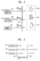
- a traffic lane dividing line extraction processing 201 is executed as one image processing.
- a road region extracting processing 202 is executed as another image processing.
- a distance information obtaining processing 203 is executed. Processing time of each processing is represented by the length of an arrow illustrated in the drawing. However, at a point of time indicated by a straight line 204, the third time processing of the traffic lane line extracting processing 201 has just been completed. Also the road region extracting processing 202 has completed the first processing, and the second processing is in the middle of being conducted. The distance information obtaining means 203 has completed the processing twice, and the third processing is in the middle of being conducted.
- the data control section 109 executes a coordinate transformation processing by which the result of each processing can be uniformly treated on the coordinate at the same time.
- the data control section 109 can be described to be an independent module provided with a function to obtain the time and movement amount of a vehicle from a reference clock and a locus estimating section which measures the vehicle position of every changing moment; and according to the time and movement amount obtained, to transform the aforementioned results of processing conducted non-synchronously onto an arbitrary coordinate.
- the road segment 205 obtained by the traffic lane dividing line segment extracting processing 201, the road region 206 obtained by the road region extracting processing 202, and the distance information 207 obtained by the distance information obtaining processing 203 can be treated transformed into the same hour and same coordinate.
- the independent module mentioned above is effective in case a plurality of image processing means to recognize a driving road of an autonomously driving vehicle and the distance information obtaining means such as the radar system 103 are provided as shown in this embodiment. Due to the abovementioned function, the following advantages can be obtained. First, the result of each processing executed non-synchronously and in parallel can be effectively transformed into the same time and onto the same coordinate. Secondly, the same processing such as a coordinate transformation can be unified. Thirdly, the load in image processing and distance information detecting processing, and the load in communication and arithmetic processing at the stage of total evaluation conducted later can be reduced. Fourthly, communication among processings can be simplified.
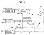
- all the processings may be started at the same time, and the inputted image and distance data may be processed at the same point. That is, when a plurality of processings, such as processing A301, processing B302, and processing C303, are synchronously operated as shown in Fig. 3, the processings 301 - 303 are started by means of communication at the same time indicated by a straight line 304 and it suffices that the inputted image and distance data may be processed at the time indicated by the straight line 305. In this case, the interval between the straight lines 304 and 305 becomes the total processing cycle.
- all processing cycles are restricted by the longest processing time, therefore a close communication between processing time of the operations becomes necessary in order to align the starting time.
- all processing cycles are restricted by the processing time of processing B302.
- the data control section 109 in this embodiment only adding the image input time to the result of each processing, all processings can be conducted individually thereafter. For example, if a driving road not far off can be recognized by a short processing cycle, even when it takes some time to recognize a driving road far off, the vehicle can be driven at a high speed when both processings are executed in parallel.
- the reliability of recognition can be greatly improved when the result of driving road recognition obtained so far and the result of processing are referred to and utilized.
- the time to execute each processing is not the same as described above, which varies depending upon circumstances.
- the coordinate systems to be used are different. Therefore, in case each processing directly exchanges the data so that the time and coordinate are transformed, communication and calculation will take a long period of time, which becomes a heavy processing load.
- the data control section 109 in this embodiment realizes a processing technique in which information required by each processing in the aforementioned system can be effectively exchanged.
- the data control section 109 as described above is an independent module having the function to obtain the time and movement amount of the vehicle from the locus estimating section which is provided with a reference clock and a means to measure the movement amount of the vehicle of every changing moment and according to the obtained result, to transform the driving road recognition result and other processing results required in the aforementioned processing carried out non-synchronously, onto an arbitrary coordinate of an arbitrary time.
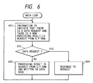
- a traffic lane dividing line extracting processing 401, a road region extracting processing 402, and a distance information obtaining processing 403 are executed in parallel.
- the processings 401 - 403 are performed utilizing and referring to the processing results with each other by the time and position correcting function of the data control section 109.
- the length of an arrow in the drawing represents the period of time necessary for conducting processing for one time. Assume that: in the road region extracting processing 402, a data request is made to the traffic lane dividing line extracting processing 401 and the distance information obtaining processing 403 at a time marked -.
- the latest processing result which has been processed immediately before the requested time is outputted to the traffic lane dividing line extracting processing 401.
- the input time of the image which is an object of the aforementioned processing is represented by a point of time at a straight line 404 in the drawing.
- the distance information obtaining processing 403 outputs the latest processing result which has been processed immediately before the requested time.
- the time at which the input data of this processing is obtained is represented by a point of time at a straight line 405 in the drawing.
- the time of input of the image to be processed is represented by a point of time at a straight line 406 in the drawing.
- the data control section 109 to which the processing results outputted from each processing are inputted corrects the time and position when input was performed to the time when the processing which made data request has obtained own input data and the estimated position of the vehicle at that time. That is, the processing results outputted from the traffic lane dividing line extracting processing 401 and the road region extracting process 402, outputted with a difference in time between the time at which one data request processing obtains input data and the time at which another data request processing obtains input data, being corrected according to the movement amount of the vehicle during that period. In the same manner, the processing result outputted from the distance information obtaining processing 403, is outputted, with the same time difference being corrected to the time when input data was obtained time of the input data requesting processing on the basis of the movement amount of the vehicle. As a result, the traffic lane dividing line and distance information data 407 transformed into an integrated time and coordinate system are obtained.
- the data control section 109 conducts time-adjustment of each processing data according to the movement amount of the vehicle, and makes it possible to utilize past driving road recognition result and mutual processing results. That is, by data control section 109, the result of each processing which is conducted in parallel, is sorted and stored by the module, and further the data of an arbitrary time and style can be calculated as requested.
- the following advantages can be provided. First, a time and coordinate-transformation can be effectively conducted, complying with various requests from a plurality of processings. Secondly, the same processing such as a coordinate transformation can be unified. Thirdly, the load in each processing such as communication and calculation time can be reduced. As a result, the communication and calculation time of the control unit can be greatly reduced, resulting in increase of the processing speed of the total processing cycle.
- this data control section 109 In order to integrally control the processing results of a plurality of image processing means and the distance information obtaining means such as the radar system 103 and to effectively perform function transforming the processing results into data of an arbitrary time on the same coordinate, the data control section 109 is structured as shown in Fig. 5.
- a road region extracting means 501 corresponds to the region extracting means 104 in Fig. 1 based on color information sent from the color camera 101.
- a traffic lane dividing line extracting means 502 corresponds to the local segment tracing means 105 and the general segment extracting means 106 which both based on image information sent from the monochromatic camera 102.
- a distance information obtaining means 503 corresponds to the radar system 103, and a locus estimating section 504 corresponds to the locus estimating section 115 in Fig. 1.
- Image data and distance information outputted from the road region extracting means 501, the traffic lane line extracting means 502 and the distance information obtaining means 503, and movement data of the vehicle outputted from the locus estimating section 504, are non-synchronously written in Dual Port RAM (D. P. RAM) 505.
- the data evaluation result, (not shown in the drawing,) outputted from the environmental description section 112, is also stored in the environmental description of DPRAM 505.
- the data control section 109 periodically reads this DPRAM 505, and when new data is found, the data is stored in data base (DB) corresponding to each means.
- This storing operation is executed by a data base writing means 506.
- Data outputted from the road region extracting means 501 is stored in DB 507 by the writing means 506, data outputted from the traffic lane dividing line extracting means 502 is stored in DB 508, data outputted from the distance information obtaining means 503 is stored in DB 509, and data outputted from the locus estimating section 504 is stored in DB 510.
- the data control section 109 searches the requested data in DB 507 - DB 510, and reads out said data with a reading means 511.
- the read-out data is transformed into a time and position coordinate requested, by time and position correction means 512.
- a correction processing is executed, using locus estimating data outputted from the locus estimating section 504 as a parameter.
- Data outputted from the road region extracting means 501 and the traffic lane dividing line extracting means 502 is transformed into a coordinate on an actual road by a projective transforming means 513 to correct time and position.
- road image information which has been projectively transformed, and distance information sent from the radar system 103 are outputted from a time and position correction means 512 into DPRAM 513, and transmitted to the data evaluating section 111. Also the result of data evaluation outputted from the data evaluating section 111 is returned to this DPRAM 513, and stored into DP 514 by the data base writing means 506.
- DB 507 - 510 and this DB 514 correspond to the data base 110 shown in Fig. 1.
- Information outputted from the time and position correction means is given to a reverse projective transformation means 515 together with the data evaluation result outputted from the data evaluating section 111, and transformed into positional coordinates on a memory for image processing. Further, the transformed positional coordinate information is given to DPRAM 505 for input use, to be used for processing in the road region extracting means 501 and the traffic lane line extracting means 502.
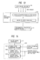
- the data control section 109 In order to find whether or not there is a new result outputted from the means 501 - 504 and whether or not there is a data request, the data control section 109 periodically reads out from DPRAM 505 information indicating the above (step 601). The read out information is judged whether it is a data request or a newly outputted result (step 602). When the result is judged to be not a data request, the result of each processing is read out from DPRAM 505 and written in DB 507 - 510 (step 603). After that, the process is returned to step 601, to execute aforementioned processing repeatedly. When the judgement result in step 602 is a data request, necessary data is read out from one of DB 507 - 510, and request response processing described later, is executed (step 604).
- this request response processing in this step 604 will be explained referring to Fig. 7.
- the request response is a request from the data evaluation section 111 or not (step 701).
- the latest image processing data and the latest obtained distance information data are read out from DB 507, 508 and DB 509 (step 702).
- the projective transformation processing is executed (step 703), and positional information is transformed onto a coordinate of an actual road. Further, the transformed information is corrected to a positional relation of the vehicle at a desired time (step 704).
- the processings up to from step 702 to step 704 are repeatedly executed by the number of times input processing was requested (step 705). Then, the corrected processing result is outputted to the data evaluating section 111 which is the source of request (step 706).
- step 701 When the judgment result of step 701 is not a request from the data evaluating section 111, the requested data is read out from the corresponding DB (step 707). Projective transformation processing is executed (step 708) so that the data can be corrected into a positional coordinate at a desired time (step 709).
- step 710 it is judged whether or not the request is made by an image processing means such as the road region extracting means 501 or the traffic lane dividing line extracting means 502 (step 710).
- step 711 When the request is from the image processing means, reverse projective transforming processing is executed (step 711), and the positional information is reversely projectively transformed into a positional coordinate on an image memory. Therefore, the processing load of the image forming means can be reduced.
- this reverse projective transformation processing is not executed. After that, the processing result is outputted to the requesting source which made the request (step 706).
- step 801 it is judged whether input time t1 at which relevant data such as image input time is inputted, is equal to time t2 or not (step 801).
- locus estimating data at time t1 is read out from locus estimation DB 510 (step 802).
- This locus estimating data is shown by a vector 901 in Fig. 9, which represents the position and direction of the vehicle in the absolute positional coordinate at time t1.
- locus estimation data at time t2 is read out from locus estimation DB 510 (step 803).
- This locus estimation data is represented by a vector 902 in Fig. 9, which shows the position and direction of the vehicle in an absolute positional coordinate at time t2.
- each point of corresponding data at time t1 is positionally corrected, and each point is corrected to a position on a relative coordinate at time t2 (step 804).
- positional correction in step 804 will be explained.
- Positions of the vehicle at time t1 and t2 are shown by points 1002 (Xt1, Yt1), 1003 (Xt2, Yt2) on an absolute positional coordinate 1001 shown in Fig. 10(a).
- This absolute positional coordinate 1001 is represented by X axis and Y axis.
- Point P (x1, y1) on a relative positional coordinate 1004 at time t1 is transformed into point P′ (x2, y2) on a relative positional coordinate 1005 at time t2 which is shown in Fig. 10(b), by this positional correction.
- the relative positional coordinate 1004 at time t1 is shown by x axis and y axis
- the relative positional coordinate 1005 at time t2 is shown by x′ axis and y′ axis.
- the directions of x axis and x′ axis of the relative positional coordinate at time t1, t2 show the directions of the vehicle at time t1, t2, and respectively form angle ⁇ 1 and angle ⁇ 2 with X axis of the absolute coordinate.
- Fig. 11 shows progress in time of each processing.
- Fig. 11(a) shows progress in time of region extracting processing in the road region extracting means 501.
- Fig. 11(b) shows progress in time of general line segment extracting processing in the traffic lane dividing line extracting means 502.
- Fig. 11(c) shows progress in time of local line segment tracing processing in the traffic lane dividing line extracting means 502.
- Each time axis is divided by a certain amount of time, and one section of time represents a period of time in which one processing is conducted. Assume that a data request is made at the present time t4 shown by a dotted line, then each processing outputs the last time processing result which is the latest processing result.
- the region extracting processing outputs the processing result of an image which has been taken in at time t1
- the general line segment extracting processing outputs the processing result of an image which has been taken in at time t2
- the local line segment tracing processing outputs the processing result of an image which has been taken in at time t3.
- the image pickup range of the autonomously running vehicle varies at time t1 - t4 as illustrated in the drawing. Therefore, images taken by a camera at time t1, t2 and t3 are as shown in Fig. 12(b), Fig. 12(c) and Fig. 12(d).
- the data control section 109 corrects the movement of the vehicle during the present time and each time by means of locus estimation in the manner described above, and expresses the data of the present time on the relative coordinate at the present time t4.
- various advantages can be obtained. For example, when the processing result of the general segment extraction is utilized, the local line segment tracing processing becomes easy. Also, when the extracted road edges are utilized, accuracy of region extracting processing can be improved. Furthermore, every image processing algorithm can utilize own processing result previously obtained.
- Road data is very important for an autonomously running vehicle, because the more correct is the road data, the more stably the system can run.
- the following technique is utilized in the data evaluating section 111. First, by utilizing a plurality of image processing results, output can be made in which mutual weak points of each processing are compensated. Secondly, each image processing result is verified under a simple condition to find whether or not the image processing result is appropriate as road data.
- the aforementioned first technique Due to the aforementioned first technique, data evaluation can be conducted more flexibly on a diversely changing environment. That is, in the case of a road on which a white line is drawn, the image processing result best suited to white line extraction can be utilized, and in the case of a road on which a white line is not drawn, the result of color region processing can be utilized.
- road data is evaluated by the second technique, more reliable road data can be made.
- the aforementioned second technique is similar to a conventional method of Kuan and Sharma (Kuan,D. and U.K Sharma). This method is shown in a document titled "Model Based Geometric Reasoning for Autonomous Road Following" (Proc. 1987 IEEE ICRA, pp.416-423 (1987)).
- the method according to this embodiment which can be applied to an ordinary road is superior to that of Kuan and Sharma in view of the fact that the technique evaluates road data by dot and not by line segment, or region data and line segment data are matched with each other.
- the data evaluating section 111 inspects first three kinds of the image processing results as described above and harmonizes the results inspected to form the road data.
- it is possible to take an inspection processing and a mutual make-up processing in reverse order that is, to have a processing flow where the three image processing results are harmonized first and the result of the harmonization is to be inspected.
- the processing in the reversed order was not adopted in the present embodiment for the following reasons.
- the amount of data to be processed is relatively small since the output data is made only based on the data inspected.
- the harmonization is not always necessary.
- the data evaluating section 1301 determines whether or not the three image processing results are appropriate as road data, under the following conditions and from these results, reliable road data is made to be outputted to the environmental description making section 112.
- the conditions of appropriateness as road data are as follows.
- the road width condition the road must have a certain road width, and as the smoothness condition, the road segment must be smooth.
- the abnormal point condition 1 number of points of road data shall be not less than a certain value.
- road data shall not exist outside the measurement range.
- road data shall not exist outside the road region.
- a road model in this embodiment is made under the following conditions. That is, as ⁇ road width condition>, the road must have a road width, and as ⁇ smoothness condition>, the line segment composing the road must be smooth Furthermore, ⁇ abnormal point condition 1> for removing abnormal data, shall have a number of points of road data not less than a certain value, as ⁇ abnormal point condition 2> road data shall not exist outside the measurement range and as ⁇ abnormal point condition 3> road data shall not exist outside the road region.
- the road model of this embodiment is simpler than the conventional road model of Kuan and Sharma (Document: "Model Based Geometric Reasoning for Autonomous Road Following", Proc.1987 IEEE ICRA, pp.416-423(1987)). That is, the road condition of this embodiment, does not include the condition of parallelism of road edges. This is because it is possible to estimate the parallelism only by road width. Further, the condition of continuity of a road is not included. The reason is that continuity can be verified to a certain extent by the environmental describing section 112. Furthermore, the system of this embodiment is different from their system in a manner that three image processing results are utilized. Accordingly, in some cases, the results of present time data evaluation and the last time data evaluation are generated from an image processing result entirely different, therefore data evaluation results can not be simply compared.
- the measurement of road width is different from the method by Kuan and Sharma in that the road width is calculated with an outer product at a level of point.
- Kuan and Sharma also use an outer product to measure a distance between an endpoint of a line segment and corresponding line segment so that the distance between line segments can be found by averaging end points.
- the outer product is used to measure distance between a point and corresponding line segment.
- this module is composed of two portions.
- One is a portion which represents the environment surrounding an autonomously running vehicle in the form of environmental description according to traffic lane dividing line data outputted from the data evaluating section and the position of an obstacle outputted from the radar system 103.
- the other is a portion which controls the environmental description that has been made in the aforementioned manner.
- the environmental description is an environmental map on which a traffic lane dividing line and an obstacle position are projected onto a ground surface coordinate, whereon the autonomously running vehicle is grasped at the origin.
- a method provided with an environmental description has the following advantages.
- output from various sensor systems can be uniformly treated.
- a portion (such as a corner) which can not be viewed by one image processing operation being in a dead angle of the camera, can be grasped by utilizing past data.
- a module of the sensor system refers to an environmental description, reliability of the system can be improved.
- vector data is adopted as basic data, and the relation of combination and junction between data is represented with a bidirectional list. Since a plurality of environmental description is made and held, when an access request is made by another module, not only it suffices that the data of environmental description which has been already processed, is being referred but it is not necessary to wait for the completion of environmental description being processed at present, with additional advantage that, NOT-IF-THEN control is not necessary, so that access control becomes easy.
- the locus control section 116 will be explained.
- the control is conducted in a manner that with regard to the sequence of points of road sent from the external environment and making the target sequence of points, a planned smooth running locus is made considering the characteristic of vehicle body and the vehicle traces this planned locus.
- the locus control section 116 is composed of a planned locus generating section 1401, a tracing section 1402 which traces this planned locus, and a steering angle control section 1403.
- the sequence of points of road and the sequence of points of target are inputted into the planned locus generating section 1401 from the motion control supervisor 114, and the vehicle own position, the absolute angle and skid angle are inputted from the locus estimating section 115.
- the planned locus generating section 1401 With regard to the inputted road sequence of points and the target, sequence of points, the planned locus generating section 1401 generates a planned driving locus in which the vehicle body characteristic with regard to the present position and direction of the vehicle is considered with consideration to the position of the vehicle, the absolute angle and the skid angle. Sent from the locus estimating section 115.
- the present condition (such as a yaw rate, vehicle speed and steering angle) of the vehicle is fed back to the planned locus generating section 1401, and the present steering angle is generated so that the locus can follow the planned locus.
- the steering angle section 1403 conducts steering angle position control with regard to a directed steering angle.
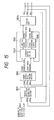
- the vehicle speed control section 117 is composed of a vehicle speed plan generating section 1501, a target vehicle speed tracing section 1502, and an actuator control section 1503.
- a sequence of points of target route speed (target distance X ref , Y ref , target speed V ref ) is inputted into the vehicle speed plan generating section 1501 from the motion control supervisor 114, and actual distance X act and actual speed V act are inputted into the vehicle speed plan generating section 1501 from a vehicle body 1504 of the autonomous driving vehicle. Then, a target vehicle speed changing pattern which satisfies the target, is generated from each given data by means of fuzzy inference.
- the target vehicle speed tracing section 1502 outputs a target throttle opening and a target brake pressure so that the vehicle speed can follow target speed V ref outputted from the vehicle speed plan generating section 1501.
- Calculation of this opening and pressure is conducted in such a manner that: actual speed V act and actual acceleration O act are detected; and calculation is conducted on the basis of the aforementioned quantity of state of the vehicle body by means of fuzzy inference.
- An actuator control section 1503 controls a throttle motor 1505 and a brake solenoid valve 1506 so that the throttle opening can agree with the target throttle opening outputted from the target vehicle speed tracing section 1502 and the pressure can agree with the target brake pressure. Due to the aforementioned control, driving of the vehicle body 1504 can be controlled and the autonomous running vehicle is driven automatically.
- data inputted and stored in the past is corrected to a desired time so that it can be evaluated. Consequently, image data which was inputted into a plurality of image pickup units and obtained after different processing time, or data obtained by the outside information obtaining means to obtain data other an image, can be integrally judged at the same time.
- the data evaluating section 111 As the data of each inputted image processing result, data in the form shown in Fig. 16 is used. As described above, in the data control section 109, all the data is projectively transformed, and all of the three image processing results are corrected to the same time. Also in Fig. 16, only input data structure by region extracting processing is shown among three data input structures, and structures of other two processings can be represented in the same manner. That is, the data structures inputted from region extracting processing, local line segment tracing processing, and general line segment extracting processing are commonly defined.
- Inputted data are grouped according to the connecting condition of each line segment.
- the maximum number of groups is 16 (group 0 - group 15).
- the maximum number of sequence of points composing the group is limited to 30.
- a line attribute is given to each segment.
- a coordinate (x, y) is assigned to the point which composes each line segment, and an attribute is given to each point.
- Sequences of points which are in an opposing relation with each other are grouped, and the groups are identified by the identification marks ID0, ID1, ....
- This opposing relation is defined as a relation in which segments are opposed with each other. However,even when there is no information of this opposing relation, the opposing relation can be identified when data evaluation is conducted on all sequences of points. That is, the opposing relation is utilized here to reduce the search region when data is evaluated.
- the number of connecting points between groups is found with regard to the groups which are in an opposing relation.
- the maximum number of the connecting points is limited to 5.
- the maximum number of groups which are in a connecting relation is also limited to 5.
- the connecting points found are given identification numbers ID0, ID1, ....
- the connecting relation indicates a connecting relation of own segment group with other different segment groups.
- Data structure inside the data evaluating section 111 is also commonly defined with regard to the data obtained by local line segment tracing processing, general segment line extracting processing, and region extracting processing.
- the data structure inside the data evaluating section will be explained, by taking as an example the data structure by general line segment extracting processing.
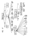
- Each data is represented in a manner that the data is hierarchically fractionalized into groups, lines and points, and connected with each other by a pointer for the convenience of reference.
- a variable which has a name of flag such as road width flag, includes a verification result obtained by data evaluation. When this flag is referred to, the most appropriate evaluation data can be ultimately produced.
- the number of groups in a connecting relation, data input time, and reject flag are first defined. This reject flag is to indicate whether input data is appropriate or not, after being processed by general line segment extracting processing.
- Input data are divided into groups g[0]... g[1] ... g[MAX _ G-1], Wp to MAX _ G.
- each group the identification number ID, number of sequences of points, number of segments, attribute of a line segment, number of opposed groups, pointer to an opposed group, number of adjacent groups, road edge flag, and region flag are defined.
- the points of each group are divided into p[0] ... p[j] ... p[MAX _ L] and maximum up to MAX _ L + 1.
- identification number ID attribute of a point
- x coordinate, y coordinate, road width, road width flag, horizontal line flag, cross flag, outside region flag, duplication flag, number of belonging groups, and pointer to the belonging groups are defined.
- the line of each group is divided into l[0] ... l[k] ... l[MAX _ L - 1] and maximum up to MAX _ L.
- the identification number, starting point, ending point, number of next line segment, and length of line segment are defined.
- each line segment is provided with next line segment NextLine [0] ... NextLine[m] ... NextLine[MAX _ N - 1] and maximum up to of MAX _ N.
- a pointer to the next line segment and an angle with the next line segment are defined.
- X and Y represent a vector, and respective start point coordinates are (x0, y0).
- the end point coordinates of vector X (X, Y) are coordinates of point P, and the end point coordinates of vector Y are (x1, y2).
- ⁇ is an angle formed by vector X and vector Y
- X x Y indicates respective outer products.
- the upper column of Table 3 shows the distance between a point and a line segment opposed to the point on the left side.
- the distance between the point and a line segment opposed on the left side which is further opposed on the left side is shown in the lower column of the table.
- line segment 1 and line segment m are in parallel with each other. Also, a norm of the outer product distance is equal to the distance between the two line segments (end of the proof).
- an abnormal result is outputted from image processing. For example, when only plane objects are aimed and projectively transformed, if a solid object is extracted and projectively transformed, the solid object is outputted in the form of an abnormally far away point. Further, a processing extracting road composing line segment from monochromatic image may mistakenly extract a line segment outside a road region. In order to remove such abnormal data, the following is carried out in the data evaluating section 111.
- the outline of this consistency verification processing is as follows.
- line segment extracting processing by monochromatic processing extraction of a line segment which appears to form a road is conducted according to monochromatic image, however a line segment outside the road region is often extracted from said processing. Therefore, in the data evaluating section 111, a line segment outside the road region is removed utilizing a road region obtained by region extracting processing.
- the data evaluating section 111 has adopted a technique in which region judgment is conducted by measuring distance utilizing above described outer product. In this technique, for each point of line segment data, the distance to each line segment of region data is calculated by outer product, to judge by the calculated value whether the point is inside or outside the region.
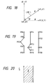
- region data is expressed by a vector.
- This vector is such that the region is expressed by the vector which always views the road region on the right side.
- a road region is expressed by a hatched portion
- the vector will be explained. That is, to judge whether each point is inside the region or outside, the vector expression is utilized.
- points p and q are investigated.
- the distance between the point and the line segment of region data, that is, the distance to boundary of the road region is found by calculating an outer product with regard to the two points. This outer product is calculated with regard to the boundary vector and the vector which is directed to points p, q from the start point of the boundary vector.
- point p When the minimum value is checked, the value of point p is negative, and that of point q is positive.
- the sign of outer product distance is defined as follows: the upper direction with regard to the drawing is defined as positive; and the lower direction is defined as negative. Therefore, the point p which outer product is negative, is judged outside the region, and point q which outer product is positive, to be inside the region.
- each point can be classified into outside or inside of the region according to the vector of region data.
- This technique is characterized in that: judgment can be flexibly conducted to determine whether a point is inside or outside the region. That is, judgment can be conducted using a norm like distance and not by a two digit value of inside or outside. This technique is useful to render it significant when treating an object relating to both inside and outside of a region with regard to a point.
- Concept (1) is set for obtaining the real time property. That is, if data is appropriate, it is sufficient for driving without going through processing.
- the system requires output road data as quickly as possible, therefore it is effective to output the data as it is.
- the region extracting processing which is one of the three image processings, does not output data except for road edge data. Also, because the general line segment extracting processing is a general processing it can not be applied to a complicated road in that condition.
- the general line segment extracting processing is useful, and if the result of verification of data sent from the general line segment extracting processing is appropriate, then the data is outputted.
- the judgement of whether the road structure is monotonous or not is estimated from the data sent from the general line segment extracting processing.
- the road structure is defined to be monotonous.
- the priority is determined in such a manner that: local line segment tracing processing > region extracting processing > general line segment extracting processing (wherein sign > represents that the left side processing has a higher priority) and when a plurality of data is appropriate, output data is determined according to this order.
- Table 4 is viewed as follows.
- the data according to the local line segment tracing processing is outputted from the data evaluating section 111.
- the result of check on appropriateness of other rows can be similarly read out from Table 4.
- Whether a line segment can be integrated or not is determined by whether or not a point in auxiliary data is smoothly connected to a line of primary data. Judgment whether the point in auxiliary data is smoothly connected or not, is determined by an angle formed by an extended line segment and a line segment on this side.
- point P is smoothly connected to straight line L means that angle q formed by a line segment 2101 connecting an endpoint of straight line L with point P and an extended line of straight line L is not more than a certain value.
- point P1 is integrated in the case of data shown in Fig. 22.
- an angle formed by a line segment connecting the endpoint of an existing line segment with point P2 and an extended line of the existing line segment is more than a reference value.
- an angle formed by a line segment based on point P1 and the existing line segment is in a range of a reference value.
- FIG. 24 A main flow chart of data evaluation processing is shown in Fig. 24.
- initialization processing is conducted (step 2401).
- three image processing results are read in (step 2402).
- the three image processing results are transformed into an internal data structure so that the processing results can be easily treated in the process of data evaluation (2403).
- appropriateness as road data is checked for each image processing results independently (step 2404).
- whether the data is appropriate or not is verified by the method described above at each point, and data which has too many inappropriate points, is judged to be abnormal.
- whether or not all data is abnormal is judged. In case all data is abnormal, an appropriate point is found in all data (even when data is abnormal, some points composing the data are appropriate), and data is integrated according to the appropriate point which was found (step 2406), to be outputted as one road data (step 2407).
- step 2405 When even one piece of appropriate data exists in the judgment of step 2405, it is subsequently judged whether or not general line segment extracting processing is normal and the road is monotonous (step 2408). At this time, the same reference as that of output road data making processing is utilized. When it has been realized that general line segment extracting processing is normal and the road is monotonous, the result of general line segment extracting processing is outputted (step 2409). If not, appropriate data is outputted according to priority (step 2410).
- the priority is determined in such a manner that: the first priority is given to the data according to local line segment tracing processing; the second priority is given to the data according to region extracting processing; and the third priority is given to the data according to general line segment extracting processing.
- Fig. 25(a) represents input data from local line segment tracing processing
- Fig. 25(b) represents input data from general line segment extracting processing
- Fig. 25(c) represents input data from region extracting processing.
- Fig. 26 shows the points which have been determined to be appropriate after the verification of appropriateness of each data. That is, appropriate points in the input data of local line segment tracing processing, general line segment extracting processing, and region extracting processing, which are shown in Fig. 25(a), (b) and (c), are shown corresponding to Fig. 26(a), (b) and (c). As described above, several points which seem to be appropriate remain in the data which has been judged to be abnormal, therefore these points are utilized. In Fig. 26, the input data from local line segment tracing processing has the most numerous appropriate points, and the input data from region extracting processing has the second most numerous appropriate points.
- the input data from local line segment tracing processing is selected for primary data
- the input data from region extracting processing is selected for auxiliary data.
- the primary and auxiliary data are integrated with reference smoothness, and one road data shown in Fig. 27 becomes the result of output.
- Characters (d), (e) and (f) in each drawing represent evaluation result of data concerning inputted data from local line segment tracing processing, evaluation result data about inputted data from general line segment extracting processing, and evaluation result data about inputted data from region extracting processing.
- Characters (g) and (h) in each drawing represent primary data and auxiliary data, and character (i) in each drawing represents output data.
- Fig. 28 shows an example in which the aforementioned three road boundary extracting processings are conducted on a curved road, and receiving from which each input data.
- Each input data shown by (a), (b), (c) in Fig. 28 is evaluated in the data evaluating section 111.
- the results of the evaluation are shown by (d), (e), (f) in Fig. 28, which seem to be correct. Therefore, all of the three input images are judged to be correct, and according to the priority described above, evaluation data obtained by local line segment tracing processing, that is, the data shown in Fig. 28(d) is outputted, and the outputted results become those as shown in Fig. 28(i).
- Fig. 29 to Fig. 31 show examples in which only data obtained by local line segment tracing processing shown by (a) in each drawing, is inputted.
- Fig. 29 shows an example in which a redundant line is extracted due to a failure in tracing processing.
- a redundant line which exists in Fig. 29(a) diagonally to the left, is removed by data evaluation as shown in Fig. 29(d).
- This input data has numerous inappropriate points so that it has been judged to be not appropriate as road data, and as data processing integration of data was conducted by integration processing.
- road data consisting only of points evaluated as appropriate, that is, evaluation data which is shown in Fig. 29(d) becomes primary data shown in Fig. 29(g), eventually becoming the output data shown in Fig. 29(i).
- Fig. 30 and Fig. 31 both show the results of local line segment tracing processing of a T-shaped road.
- the far off boundary of the T-shaped road is not extracted, however, in Fig. 31, the far off boundary is extracted. That is, in Fig. 30, a line segment corresponding to an end of a boundary of the T-shaped road in the data shown in Fig. 30(a) can not be found. Therefore, the points after the corner at the end of the T-shaped road are processed bas being inappropriate, to become the data evaluation result as shown in Fig. 30(d). Inappropriate points are so numerous that data integration processing is being conducted. However, the only available data is the data of local line segment tracing processing, therefore the evaluation data shown in Fig. 30(d) becomes the primary data shown in Fig. 30(g), to become the output data shown in Fig. 30(i) in that condition.
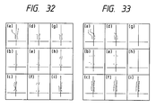
- Fig. 32 is an example which allows to easily grasp the function of road structure verification by road width and the function of integration of different kinds of data.
- Points of input data shown in Fig. 32(a) sent from local line segment tracing processing are judged not to be appropriate since the far end of the road is widened. Therefore, these points are removed by means of data evaluation, to obtain evaluation data shown in Fig. 32(d).
- points of input data shown in Fig. 32(b) sent from general line segment extracting processing are judged not appropriate since the road width of the far side is narrow, to obtain evaluation data shown in Fig. 32(e).
- the points in the middle distance are judged not appropriate since the road width of the middle distance is narrow, to obtain evaluation data shown in Fig. 32(f).
- the primary data for integration is the evaluation result data of local line segment tracing processing shown in Fig. 32(g).
- Auxiliary data shown in Fig. 32(h) is a group of appropriate points within input data sent from region extracting processing.
- Fig. 33 is an example which clearly shows the verification of consistency between input data sent from region extracting processing and line segment extracting data obtained by small region tracing processing.
- Evaluation data shown in Fig. 33(f) can be obtained from input data sent from region extracting processing shown in Fig. 33(c).
- the points outside the road expressed in evaluation data of region extracting processing are judged abnormal. Therefore, with regard to each line segment extracting data obtained by small region tracing processing, the points outside the road processed by region extracting processing are removed, to become evaluation data shown in Fig. 33(d) and Fig. 33(e). Since input data inputted from region extracting processing does not include an abnormal point, the data is judged appropriate as road data, and outputted in the form of data shown in Fig. 33(i).
- a plurality of road data which have been corrected to the same time are inputted, and each road data is verified according to the road model expressed by a level of point, and then one road data is made according to a plurality of road data obtained after verification.
- a road is recognized in such a manner that: the road is verified by a road model which is expressed by line segments; and because too much weight is given to parallelism of the road model, a complicated road shape such as a branched road or multi-traffic lane road could not be verified.
- parallel line segments inside the road are obtained, as a result, so that the road recognition can be also conducted on a branched or multi-traffic lane road.
- data evaluation is conducted not on a line segment level but on a point level, so that a vehicle running road having a complicated shape can be recognized. Therefore, a road closer to reality having a branched portion, etc. can be recognized whereas only a monotonous road having one traffic lane is recognized by a conventional method.
- Likeness to a vehicle running road is judged by the sequence of points data outputted from a plurality of road boundary extracting processings, so that the reliability of obtained data is improved. Therefore, stable road data can be obtained.
- an autonomously running vehicle can be automatically driven in a condition similar to a real driving condition.
Landscapes
- Engineering & Computer Science (AREA)
- Physics & Mathematics (AREA)
- General Physics & Mathematics (AREA)
- Remote Sensing (AREA)
- Automation & Control Theory (AREA)
- Radar, Positioning & Navigation (AREA)
- Aviation & Aerospace Engineering (AREA)
- Multimedia (AREA)
- Theoretical Computer Science (AREA)
- Computer Vision & Pattern Recognition (AREA)
- Mechanical Engineering (AREA)
- Electromagnetism (AREA)
- Transportation (AREA)
- Human Computer Interaction (AREA)
- Acoustics & Sound (AREA)
- Traffic Control Systems (AREA)
- Image Processing (AREA)
Applications Claiming Priority (4)
| Application Number | Priority Date | Filing Date | Title |
|---|---|---|---|
| JP2335732A JP2836949B2 (ja) | 1990-11-30 | 1990-11-30 | 自律移動体の制御装置 |
| JP335732/90 | 1990-11-30 | ||
| JP335731/90 | 1990-11-30 | ||
| JP33573190A JP3200062B2 (ja) | 1990-11-30 | 1990-11-30 | 移動路データに対する評価方法 |
Publications (3)
| Publication Number | Publication Date |
|---|---|
| EP0488828A2 true EP0488828A2 (de) | 1992-06-03 |
| EP0488828A3 EP0488828A3 (en) | 1992-07-15 |
| EP0488828B1 EP0488828B1 (de) | 1996-08-14 |
Family
ID=26575258
Family Applications (1)
| Application Number | Title | Priority Date | Filing Date |
|---|---|---|---|
| EP91311210A Expired - Lifetime EP0488828B1 (de) | 1990-11-30 | 1991-12-02 | Steuervorrichtung für einen sich selbständig bewegenden Körper und Verfahren zur Auswertung der Daten davon |
Country Status (3)
| Country | Link |
|---|---|
| US (1) | US5307419A (de) |
| EP (1) | EP0488828B1 (de) |
| DE (1) | DE69121369T2 (de) |
Cited By (11)
| Publication number | Priority date | Publication date | Assignee | Title |
|---|---|---|---|---|
| EP0738946A1 (de) * | 1995-04-17 | 1996-10-23 | Honda Giken Kogyo Kabushiki Kaisha | Automatisches Kurssteuersystem für ein Fahrzeug |
| EP0782118A1 (de) * | 1995-12-26 | 1997-07-02 | Aisin Aw Co., Ltd. | Fahrzeugnavigationssystem |
| WO1997039394A1 (en) * | 1996-04-15 | 1997-10-23 | Apogeum Ab | A method for determining the positions of a plurality of anonymous fixed reference objects for mobile surface transportation and a device for determining said positions |
| EP0913751A1 (de) * | 1997-11-03 | 1999-05-06 | Volkswagen Aktiengesellschaft | Autonomes Fahrzeug und Verfahren zur Steuerung eines autonomen Fahrzeuges |
| EP1035509A1 (de) * | 1999-03-12 | 2000-09-13 | Hyundai Motor Company | Bahnmodellierungsverfahren für Spurabdriftwarnungsystem |
| EP1372126A1 (de) * | 2002-06-14 | 2003-12-17 | Bayerische Motoren Werke Aktiengesellschaft | Verfahren zur Verwendung der Video-Bildverarbeitung für Fahrerassistenzsysteme |
| CN103270543A (zh) * | 2010-12-24 | 2013-08-28 | 株式会社日立制作所 | 驾驶辅助装置 |
| DE10117237B4 (de) * | 2000-04-07 | 2013-09-26 | Honda Giken Kogyo K.K. | Fahrzeugsteuervorrichtung |
| US8917904B2 (en) | 2008-04-24 | 2014-12-23 | GM Global Technology Operations LLC | Vehicle clear path detection |
| US9852357B2 (en) | 2008-04-24 | 2017-12-26 | GM Global Technology Operations LLC | Clear path detection using an example-based approach |
| CN117338285A (zh) * | 2023-10-31 | 2024-01-05 | 西南交通大学 | 一种脊柱侧弯检测装置及方法 |
Families Citing this family (69)
| Publication number | Priority date | Publication date | Assignee | Title |
|---|---|---|---|---|
| US5838562A (en) * | 1990-02-05 | 1998-11-17 | Caterpillar Inc. | System and a method for enabling a vehicle to track a preset path |
| FR2674354A1 (fr) * | 1991-03-22 | 1992-09-25 | Thomson Csf | Procede d'analyse de sequences d'images routieres, dispositif pour sa mise en óoeuvre et son application a la detection d'obstacles. |
| US5568589A (en) * | 1992-03-09 | 1996-10-22 | Hwang; Jin S. | Self-propelled cleaning machine with fuzzy logic control |
| US6822563B2 (en) | 1997-09-22 | 2004-11-23 | Donnelly Corporation | Vehicle imaging system with accessory control |
| US5877897A (en) | 1993-02-26 | 1999-03-02 | Donnelly Corporation | Automatic rearview mirror, vehicle lighting control and vehicle interior monitoring system using a photosensor array |
| JP3468428B2 (ja) * | 1993-03-24 | 2003-11-17 | 富士重工業株式会社 | 車輌用距離検出装置 |
| JPH06300581A (ja) * | 1993-04-15 | 1994-10-28 | Fuji Heavy Ind Ltd | 車輛の軌道追従制御装置 |
| JP3169483B2 (ja) * | 1993-06-25 | 2001-05-28 | 富士通株式会社 | 道路環境認識装置 |
| DE4408328C2 (de) * | 1994-03-11 | 2002-09-26 | Siemens Ag | Verfahren zum Aufbau einer zellular strukturierten Umgebungskarte von einer selbstbeweglichen mobilen Einheit, welche sich mit Hilfe von auf Wellenreflexion basierenden Sensoren orientiert |
| JPH08167100A (ja) * | 1994-12-12 | 1996-06-25 | Hisaji Nakamura | 操縦装置 |
| US5987174A (en) * | 1995-04-26 | 1999-11-16 | Hitachi, Ltd. | Image processing apparatus for vehicles |
| US6891563B2 (en) | 1996-05-22 | 2005-05-10 | Donnelly Corporation | Vehicular vision system |
| JP3018949B2 (ja) * | 1995-08-10 | 2000-03-13 | 日本電気株式会社 | 文字読取装置およびその方法 |
| JP3369368B2 (ja) * | 1995-10-11 | 2003-01-20 | 富士通株式会社 | 画像処理装置 |
| US5887268A (en) * | 1995-10-31 | 1999-03-23 | Honda Giken Kogyo Kabushiki Kaisha | Automatically driven motor vehicle |
| US5719762A (en) * | 1995-11-06 | 1998-02-17 | The United States Of America As Represented By The Secretary Of The Navy | Method of controlling a vehicle to make a combination of arbitrary translational and rotational motions |
| KR100270523B1 (ko) * | 1995-12-27 | 2000-11-01 | 정몽규 | 도로 조건에 따른 카메라 제어기능을 구비한 무인 자동차 시스템 |
| US6259827B1 (en) | 1996-03-21 | 2001-07-10 | Cognex Corporation | Machine vision methods for enhancing the contrast between an object and its background using multiple on-axis images |
| US7655894B2 (en) | 1996-03-25 | 2010-02-02 | Donnelly Corporation | Vehicular image sensing system |
| JP3983324B2 (ja) * | 1997-01-09 | 2007-09-26 | 富士重工業株式会社 | 車両の走行レーン逸脱防止装置 |
| US6075881A (en) | 1997-03-18 | 2000-06-13 | Cognex Corporation | Machine vision methods for identifying collinear sets of points from an image |
| US6608647B1 (en) | 1997-06-24 | 2003-08-19 | Cognex Corporation | Methods and apparatus for charge coupled device image acquisition with independent integration and readout |
| JPH1186182A (ja) * | 1997-09-01 | 1999-03-30 | Honda Motor Co Ltd | 自動運転制御システム |
| US6381375B1 (en) | 1998-02-20 | 2002-04-30 | Cognex Corporation | Methods and apparatus for generating a projection of an image |
| US6687402B1 (en) | 1998-12-18 | 2004-02-03 | Cognex Corporation | Machine vision methods and systems for boundary feature comparison of patterns and images |
| US6381366B1 (en) | 1998-12-18 | 2002-04-30 | Cognex Corporation | Machine vision methods and system for boundary point-based comparison of patterns and images |
| US7366595B1 (en) * | 1999-06-25 | 2008-04-29 | Seiko Epson Corporation | Vehicle drive assist system |
| US6296317B1 (en) * | 1999-10-29 | 2001-10-02 | Carnegie Mellon University | Vision-based motion sensor for mining machine control |
| US6684402B1 (en) | 1999-12-01 | 2004-01-27 | Cognex Technology And Investment Corporation | Control methods and apparatus for coupling multiple image acquisition devices to a digital data processor |
| US6748104B1 (en) | 2000-03-24 | 2004-06-08 | Cognex Corporation | Methods and apparatus for machine vision inspection using single and multiple templates or patterns |
| US7006669B1 (en) | 2000-12-31 | 2006-02-28 | Cognex Corporation | Machine vision method and apparatus for thresholding images of non-uniform materials |
| US6681177B2 (en) * | 2001-01-30 | 2004-01-20 | Rajashri Joshi | Bowing coefficient representation of curvature of geographic features |
| JP4159794B2 (ja) * | 2001-05-02 | 2008-10-01 | 本田技研工業株式会社 | 画像処理装置及び方法 |
| US7574045B2 (en) * | 2001-07-27 | 2009-08-11 | Matrox Electronic Systems Ltd. | Model-based recognition of objects using a calibrated image system |
| JP3822468B2 (ja) * | 2001-07-18 | 2006-09-20 | 株式会社東芝 | 画像処理装置及びその方法 |
| EP1504276B1 (de) | 2002-05-03 | 2012-08-08 | Donnelly Corporation | Objektdetektionssystem für ein fahrzeug |
| US6725139B2 (en) * | 2002-08-19 | 2004-04-20 | Ford Global Technologies, Llc | Steerable night vision system |
| US7050909B2 (en) * | 2004-01-29 | 2006-05-23 | Northrop Grumman Corporation | Automatic taxi manager |
| US7526103B2 (en) | 2004-04-15 | 2009-04-28 | Donnelly Corporation | Imaging system for vehicle |
| JP4092308B2 (ja) * | 2004-06-02 | 2008-05-28 | トヨタ自動車株式会社 | 境界線検出装置 |
| US7974778B2 (en) * | 2004-09-17 | 2011-07-05 | Honda Motor Co., Ltd. | Vehicular control object determination system and vehicular travel locus estimation system |
| US7881496B2 (en) | 2004-09-30 | 2011-02-01 | Donnelly Corporation | Vision system for vehicle |
| US7639861B2 (en) | 2005-09-14 | 2009-12-29 | Cognex Technology And Investment Corporation | Method and apparatus for backlighting a wafer during alignment |
| US8111904B2 (en) * | 2005-10-07 | 2012-02-07 | Cognex Technology And Investment Corp. | Methods and apparatus for practical 3D vision system |
| US7933897B2 (en) | 2005-10-12 | 2011-04-26 | Google Inc. | Entity display priority in a distributed geographic information system |
| JP4793094B2 (ja) * | 2006-05-17 | 2011-10-12 | 株式会社デンソー | 走行環境認識装置 |
| JP2007316966A (ja) * | 2006-05-26 | 2007-12-06 | Fujitsu Ltd | 移動ロボット、その制御方法及びプログラム |
| JP4232794B2 (ja) * | 2006-05-31 | 2009-03-04 | アイシン・エィ・ダブリュ株式会社 | 運転支援方法及び運転支援装置 |
| WO2008024639A2 (en) | 2006-08-11 | 2008-02-28 | Donnelly Corporation | Automatic headlamp control system |
| US8162584B2 (en) * | 2006-08-23 | 2012-04-24 | Cognex Corporation | Method and apparatus for semiconductor wafer alignment |
| US7512487B1 (en) * | 2006-11-02 | 2009-03-31 | Google Inc. | Adaptive and personalized navigation system |
| US7680749B1 (en) * | 2006-11-02 | 2010-03-16 | Google Inc. | Generating attribute models for use in adaptive navigation systems |
| FR2921027B1 (fr) | 2007-09-17 | 2010-02-26 | Valeo Vision | Dispositif d'aide a la conduite pour vehicule automobile comportant un systeme de capture d'images stereoscopique |
| JP5039765B2 (ja) * | 2009-09-17 | 2012-10-03 | 日立オートモティブシステムズ株式会社 | 車両制御装置 |
| US9198575B1 (en) | 2011-02-15 | 2015-12-01 | Guardvant, Inc. | System and method for determining a level of operator fatigue |
| US9952046B1 (en) | 2011-02-15 | 2018-04-24 | Guardvant, Inc. | Cellular phone and personal protective equipment usage monitoring system |
| TWI428249B (zh) * | 2011-08-23 | 2014-03-01 | Ind Tech Res Inst | 車載裝置及其行車輔助系統與行車輔助資訊提供方法 |
| US8521352B1 (en) * | 2012-05-07 | 2013-08-27 | Google Inc. | Controlling a vehicle having inadequate map data |
| US9063548B1 (en) | 2012-12-19 | 2015-06-23 | Google Inc. | Use of previous detections for lane marker detection |
| US9081385B1 (en) | 2012-12-21 | 2015-07-14 | Google Inc. | Lane boundary detection using images |
| CN105493141B (zh) * | 2013-08-23 | 2018-09-14 | 哈曼国际工业有限公司 | 非结构化道路边界检测 |
| US9081383B1 (en) * | 2014-01-22 | 2015-07-14 | Google Inc. | Enhancing basic roadway-intersection models using high intensity image data |
| JP6561431B2 (ja) * | 2014-05-14 | 2019-08-21 | 株式会社デンソー | 境界線認識装置および境界線認識プログラム |
| CN112146669B (zh) * | 2015-02-10 | 2024-08-27 | 御眼视觉技术有限公司 | 服务器系统、方法及机器可读介质 |
| KR101755870B1 (ko) * | 2015-10-28 | 2017-07-19 | 현대자동차주식회사 | 차선의 오인식 정보를 보정하는 방법 |
| CN106529415A (zh) * | 2016-10-16 | 2017-03-22 | 北海益生源农贸有限责任公司 | 结合特征和模型的道路检测方法 |
| JP6772944B2 (ja) | 2017-04-19 | 2020-10-21 | トヨタ自動車株式会社 | 自動運転システム |
| CN114945959B (zh) * | 2020-11-23 | 2023-06-20 | 深圳元戎启行科技有限公司 | 行驶轨迹确定方法、装置、计算机设备和存储介质 |
| US20230296404A1 (en) * | 2022-03-21 | 2023-09-21 | Here Global B.V. | System and method for updating a map according to feature locations |
Family Cites Families (7)
| Publication number | Priority date | Publication date | Assignee | Title |
|---|---|---|---|---|
| US4906940A (en) * | 1987-08-24 | 1990-03-06 | Science Applications International Corporation | Process and apparatus for the automatic detection and extraction of features in images and displays |
| JP2660727B2 (ja) * | 1988-08-10 | 1997-10-08 | 本田技研工業株式会社 | 自動走行装置 |
| US5109425A (en) * | 1988-09-30 | 1992-04-28 | The United States Of America As Represented By The United States National Aeronautics And Space Administration | Method and apparatus for predicting the direction of movement in machine vision |
| JP2669031B2 (ja) * | 1989-02-28 | 1997-10-27 | 日産自動車株式会社 | 自律走行車両 |
| JPH07111734B2 (ja) * | 1989-03-30 | 1995-11-29 | 本田技研工業株式会社 | 走行路判別方法 |
| US5144685A (en) * | 1989-03-31 | 1992-09-01 | Honeywell Inc. | Landmark recognition for autonomous mobile robots |
| US5142659A (en) * | 1989-04-18 | 1992-08-25 | Texas Instruments Incorporated | Estimation of local surface geometry from relative range images for object recognition |
-
1991
- 1991-12-02 EP EP91311210A patent/EP0488828B1/de not_active Expired - Lifetime
- 1991-12-02 US US07/801,708 patent/US5307419A/en not_active Expired - Lifetime
- 1991-12-02 DE DE69121369T patent/DE69121369T2/de not_active Expired - Fee Related
Cited By (15)
| Publication number | Priority date | Publication date | Assignee | Title |
|---|---|---|---|---|
| EP0738946A1 (de) * | 1995-04-17 | 1996-10-23 | Honda Giken Kogyo Kabushiki Kaisha | Automatisches Kurssteuersystem für ein Fahrzeug |
| EP0782118A1 (de) * | 1995-12-26 | 1997-07-02 | Aisin Aw Co., Ltd. | Fahrzeugnavigationssystem |
| US6018697A (en) * | 1995-12-26 | 2000-01-25 | Aisin Aw Co., Ltd. | Navigation system for vehicles |
| WO1997039394A1 (en) * | 1996-04-15 | 1997-10-23 | Apogeum Ab | A method for determining the positions of a plurality of anonymous fixed reference objects for mobile surface transportation and a device for determining said positions |
| US6012003A (en) * | 1996-04-15 | 2000-01-04 | Apogeum Ab | Method for determining the positions of a plurality of anonymous fixed reference objects for mobile surface transportation and a device for determining said positions |
| EP0913751A1 (de) * | 1997-11-03 | 1999-05-06 | Volkswagen Aktiengesellschaft | Autonomes Fahrzeug und Verfahren zur Steuerung eines autonomen Fahrzeuges |
| EP1035509A1 (de) * | 1999-03-12 | 2000-09-13 | Hyundai Motor Company | Bahnmodellierungsverfahren für Spurabdriftwarnungsystem |
| DE10117237B4 (de) * | 2000-04-07 | 2013-09-26 | Honda Giken Kogyo K.K. | Fahrzeugsteuervorrichtung |
| EP1372126A1 (de) * | 2002-06-14 | 2003-12-17 | Bayerische Motoren Werke Aktiengesellschaft | Verfahren zur Verwendung der Video-Bildverarbeitung für Fahrerassistenzsysteme |
| US8917904B2 (en) | 2008-04-24 | 2014-12-23 | GM Global Technology Operations LLC | Vehicle clear path detection |
| US9852357B2 (en) | 2008-04-24 | 2017-12-26 | GM Global Technology Operations LLC | Clear path detection using an example-based approach |
| CN103270543A (zh) * | 2010-12-24 | 2013-08-28 | 株式会社日立制作所 | 驾驶辅助装置 |
| EP2657920A4 (de) * | 2010-12-24 | 2014-06-25 | Hitachi Ltd | Fahrassistenzvorrichtung |
| CN103270543B (zh) * | 2010-12-24 | 2015-05-20 | 株式会社日立制作所 | 驾驶辅助装置 |
| CN117338285A (zh) * | 2023-10-31 | 2024-01-05 | 西南交通大学 | 一种脊柱侧弯检测装置及方法 |
Also Published As
| Publication number | Publication date |
|---|---|
| US5307419A (en) | 1994-04-26 |
| DE69121369T2 (de) | 1997-01-09 |
| EP0488828A3 (en) | 1992-07-15 |
| EP0488828B1 (de) | 1996-08-14 |
| DE69121369D1 (de) | 1996-09-19 |
Similar Documents
| Publication | Publication Date | Title |
|---|---|---|
| EP0488828B1 (de) | Steuervorrichtung für einen sich selbständig bewegenden Körper und Verfahren zur Auswertung der Daten davon | |
| EP3842754A1 (de) | System und verfahren zur erkennung von änderungen in einem objekt zur aktualisierung einer hochauflösenden karte | |
| US5790403A (en) | Lane image processing system for vehicle | |
| US5220508A (en) | Position and heading detecting device for self controlled vehicle | |
| US11348278B2 (en) | Object detection | |
| JPH0727541A (ja) | 道路形状及び自車両位置の計測装置 | |
| JPH07103715A (ja) | 視覚に基く三次元位置および姿勢の認識方法ならびに視覚に基く三次元位置および姿勢の認識装置 | |
| Manivannan et al. | Vision based intelligent vehicle steering control using single camera for automated highway system | |
| Armingol et al. | Landmark perception planning for mobile robot localization | |
| JP3200062B2 (ja) | 移動路データに対する評価方法 | |
| KR102603877B1 (ko) | 차량의 정밀 측위 방법 및 장치 | |
| CN118251638A (zh) | 辅助或自动车辆导引方法 | |
| Chiu et al. | Sub-meter vehicle navigation using efficient pre-mapped visual landmarks | |
| Lee et al. | Localization based on visibility sectors using range sensors | |
| JPH1139464A (ja) | 車両用画像処理装置 | |
| Cucchiara et al. | Efficient Stereo Vision for Obstacle Detection and AGV Navigation. | |
| Schleicher et al. | Real-time stereo visual slam in large-scale environments based on sift fingerprints | |
| 後方カメラ用画像処理技術 et al. | Image processing technology for rear view camera (1): Development of lane detection system | |
| CN117755300A (zh) | 一种循迹倒车路径提取方法、装置、存储介质及电子设备 | |
| JP2923664B2 (ja) | 自動走行装置 | |
| JP2836949B2 (ja) | 自律移動体の制御装置 | |
| Aufrère et al. | Road detection and vehicle tracking by vision for adaptive cruise control | |
| Shi | Application of LiDAR and Visual SLAM Technology in Automatic Driving | |
| Li et al. | CAD-vision-range-based self-localization for mobile robot using one landmark | |
| Choi et al. | Applications of moving windows technique to autonomous vehicle navigation |
Legal Events
| Date | Code | Title | Description |
|---|---|---|---|
| PUAI | Public reference made under article 153(3) epc to a published international application that has entered the european phase |
Free format text: ORIGINAL CODE: 0009012 |
|
| PUAL | Search report despatched |
Free format text: ORIGINAL CODE: 0009013 |
|
| AK | Designated contracting states |
Kind code of ref document: A2 Designated state(s): DE FR GB |
|
| AK | Designated contracting states |
Kind code of ref document: A3 Designated state(s): DE FR GB |
|
| 17P | Request for examination filed |
Effective date: 19920908 |
|
| 17Q | First examination report despatched |
Effective date: 19940614 |
|
| GRAG | Despatch of communication of intention to grant |
Free format text: ORIGINAL CODE: EPIDOS AGRA |
|
| GRAH | Despatch of communication of intention to grant a patent |
Free format text: ORIGINAL CODE: EPIDOS IGRA |
|
| GRAH | Despatch of communication of intention to grant a patent |
Free format text: ORIGINAL CODE: EPIDOS IGRA |
|
| GRAA | (expected) grant |
Free format text: ORIGINAL CODE: 0009210 |
|
| AK | Designated contracting states |
Kind code of ref document: B1 Designated state(s): DE FR GB |
|
| REF | Corresponds to: |
Ref document number: 69121369 Country of ref document: DE Date of ref document: 19960919 |
|
| ET | Fr: translation filed | ||
| PLBE | No opposition filed within time limit |
Free format text: ORIGINAL CODE: 0009261 |
|
| STAA | Information on the status of an ep patent application or granted ep patent |
Free format text: STATUS: NO OPPOSITION FILED WITHIN TIME LIMIT |
|
| 26N | No opposition filed | ||
| REG | Reference to a national code |
Ref country code: GB Ref legal event code: IF02 |
|
| PGFP | Annual fee paid to national office [announced via postgrant information from national office to epo] |
Ref country code: GB Payment date: 20061129 Year of fee payment: 16 |
|
| PGFP | Annual fee paid to national office [announced via postgrant information from national office to epo] |
Ref country code: DE Payment date: 20061130 Year of fee payment: 16 |
|
| PGFP | Annual fee paid to national office [announced via postgrant information from national office to epo] |
Ref country code: FR Payment date: 20061208 Year of fee payment: 16 |
|
| GBPC | Gb: european patent ceased through non-payment of renewal fee |
Effective date: 20071202 |
|
| PG25 | Lapsed in a contracting state [announced via postgrant information from national office to epo] |
Ref country code: DE Free format text: LAPSE BECAUSE OF NON-PAYMENT OF DUE FEES Effective date: 20080701 |
|
| REG | Reference to a national code |
Ref country code: FR Ref legal event code: ST Effective date: 20081020 |
|
| PG25 | Lapsed in a contracting state [announced via postgrant information from national office to epo] |
Ref country code: GB Free format text: LAPSE BECAUSE OF NON-PAYMENT OF DUE FEES Effective date: 20071202 |
|
| PG25 | Lapsed in a contracting state [announced via postgrant information from national office to epo] |
Ref country code: FR Free format text: LAPSE BECAUSE OF NON-PAYMENT OF DUE FEES Effective date: 20071231 |