EP0488858B1 - Herstellungsweise einer Brennkammerwand, insbesondere für einen Raketenmotor und durch diese Methode hergestellte Brennkammer - Google Patents
Herstellungsweise einer Brennkammerwand, insbesondere für einen Raketenmotor und durch diese Methode hergestellte Brennkammer Download PDFInfo
- Publication number
- EP0488858B1 EP0488858B1 EP91403150A EP91403150A EP0488858B1 EP 0488858 B1 EP0488858 B1 EP 0488858B1 EP 91403150 A EP91403150 A EP 91403150A EP 91403150 A EP91403150 A EP 91403150A EP 0488858 B1 EP0488858 B1 EP 0488858B1
- Authority
- EP
- European Patent Office
- Prior art keywords
- additional
- outer shell
- shell
- coating
- metal
- Prior art date
- Legal status (The legal status is an assumption and is not a legal conclusion. Google has not performed a legal analysis and makes no representation as to the accuracy of the status listed.)
- Expired - Lifetime
Links
- 238000000034 method Methods 0.000 title claims description 62
- 238000002485 combustion reaction Methods 0.000 title claims description 52
- 238000004519 manufacturing process Methods 0.000 title claims description 35
- 238000000576 coating method Methods 0.000 claims description 63
- 239000011248 coating agent Substances 0.000 claims description 61
- 238000001816 cooling Methods 0.000 claims description 51
- 238000010438 heat treatment Methods 0.000 claims description 34
- 229910052751 metal Inorganic materials 0.000 claims description 30
- 239000002184 metal Substances 0.000 claims description 30
- 238000003466 welding Methods 0.000 claims description 27
- 239000012530 fluid Substances 0.000 claims description 16
- 239000000463 material Substances 0.000 claims description 16
- 239000000956 alloy Substances 0.000 claims description 11
- 229910045601 alloy Inorganic materials 0.000 claims description 11
- 238000004663 powder metallurgy Methods 0.000 claims description 11
- 238000003754 machining Methods 0.000 claims description 10
- 239000000126 substance Substances 0.000 claims description 10
- 239000000843 powder Substances 0.000 claims description 9
- 239000000919 ceramic Substances 0.000 claims description 7
- 230000000712 assembly Effects 0.000 claims description 6
- 238000000429 assembly Methods 0.000 claims description 6
- 238000005219 brazing Methods 0.000 claims description 6
- 239000012809 cooling fluid Substances 0.000 claims description 6
- 239000000203 mixture Substances 0.000 claims description 6
- 238000007493 shaping process Methods 0.000 claims description 6
- 239000002131 composite material Substances 0.000 claims description 5
- 238000009792 diffusion process Methods 0.000 claims description 3
- 238000004804 winding Methods 0.000 claims description 3
- 238000006555 catalytic reaction Methods 0.000 claims description 2
- 238000009713 electroplating Methods 0.000 claims 1
- PXHVJJICTQNCMI-UHFFFAOYSA-N Nickel Chemical compound [Ni] PXHVJJICTQNCMI-UHFFFAOYSA-N 0.000 description 14
- 238000005056 compaction Methods 0.000 description 9
- 238000005516 engineering process Methods 0.000 description 8
- 229910052759 nickel Inorganic materials 0.000 description 7
- 238000004090 dissolution Methods 0.000 description 6
- 238000004070 electrodeposition Methods 0.000 description 6
- 239000007788 liquid Substances 0.000 description 6
- RYGMFSIKBFXOCR-UHFFFAOYSA-N Copper Chemical compound [Cu] RYGMFSIKBFXOCR-UHFFFAOYSA-N 0.000 description 5
- 230000015572 biosynthetic process Effects 0.000 description 5
- 230000001747 exhibiting effect Effects 0.000 description 5
- 239000007769 metal material Substances 0.000 description 5
- 240000008042 Zea mays Species 0.000 description 4
- 239000011324 bead Substances 0.000 description 4
- 229910052802 copper Inorganic materials 0.000 description 4
- 239000010949 copper Substances 0.000 description 4
- 239000007789 gas Substances 0.000 description 4
- 239000003380 propellant Substances 0.000 description 4
- VYPSYNLAJGMNEJ-UHFFFAOYSA-N silicon dioxide Inorganic materials O=[Si]=O VYPSYNLAJGMNEJ-UHFFFAOYSA-N 0.000 description 4
- 235000012239 silicon dioxide Nutrition 0.000 description 3
- KWGRBVOPPLSCSI-WPRPVWTQSA-N (-)-ephedrine Chemical compound CN[C@@H](C)[C@H](O)C1=CC=CC=C1 KWGRBVOPPLSCSI-WPRPVWTQSA-N 0.000 description 2
- RTAQQCXQSZGOHL-UHFFFAOYSA-N Titanium Chemical compound [Ti] RTAQQCXQSZGOHL-UHFFFAOYSA-N 0.000 description 2
- 229910010293 ceramic material Inorganic materials 0.000 description 2
- 238000005520 cutting process Methods 0.000 description 2
- 230000003628 erosive effect Effects 0.000 description 2
- 239000004033 plastic Substances 0.000 description 2
- BASFCYQUMIYNBI-UHFFFAOYSA-N platinum Chemical compound [Pt] BASFCYQUMIYNBI-UHFFFAOYSA-N 0.000 description 2
- 230000008569 process Effects 0.000 description 2
- 239000010453 quartz Substances 0.000 description 2
- 239000011347 resin Substances 0.000 description 2
- 229920005989 resin Polymers 0.000 description 2
- 229910052709 silver Inorganic materials 0.000 description 2
- 239000004332 silver Substances 0.000 description 2
- WFKWXMTUELFFGS-UHFFFAOYSA-N tungsten Chemical compound [W] WFKWXMTUELFFGS-UHFFFAOYSA-N 0.000 description 2
- 229910052721 tungsten Inorganic materials 0.000 description 2
- 239000010937 tungsten Substances 0.000 description 2
- 241000256815 Apocrita Species 0.000 description 1
- 229910000881 Cu alloy Inorganic materials 0.000 description 1
- 241001415961 Gaviidae Species 0.000 description 1
- 229910000990 Ni alloy Inorganic materials 0.000 description 1
- 229910001069 Ti alloy Inorganic materials 0.000 description 1
- 230000009471 action Effects 0.000 description 1
- 230000001464 adherent effect Effects 0.000 description 1
- PNEYBMLMFCGWSK-UHFFFAOYSA-N aluminium oxide Inorganic materials [O-2].[O-2].[O-2].[Al+3].[Al+3] PNEYBMLMFCGWSK-UHFFFAOYSA-N 0.000 description 1
- 238000007664 blowing Methods 0.000 description 1
- 238000004364 calculation method Methods 0.000 description 1
- CREMABGTGYGIQB-UHFFFAOYSA-N carbon carbon Chemical compound C.C CREMABGTGYGIQB-UHFFFAOYSA-N 0.000 description 1
- 239000011203 carbon fibre reinforced carbon Substances 0.000 description 1
- 210000004027 cell Anatomy 0.000 description 1
- 229910017052 cobalt Inorganic materials 0.000 description 1
- 239000010941 cobalt Substances 0.000 description 1
- GUTLYIVDDKVIGB-UHFFFAOYSA-N cobalt atom Chemical compound [Co] GUTLYIVDDKVIGB-UHFFFAOYSA-N 0.000 description 1
- 229910052681 coesite Inorganic materials 0.000 description 1
- 239000004020 conductor Substances 0.000 description 1
- 239000002826 coolant Substances 0.000 description 1
- 229910052593 corundum Inorganic materials 0.000 description 1
- 229910052906 cristobalite Inorganic materials 0.000 description 1
- 238000000151 deposition Methods 0.000 description 1
- 230000008021 deposition Effects 0.000 description 1
- 239000006185 dispersion Substances 0.000 description 1
- 238000004049 embossing Methods 0.000 description 1
- 229940082150 encore Drugs 0.000 description 1
- 210000000887 face Anatomy 0.000 description 1
- 239000000835 fiber Substances 0.000 description 1
- 239000008187 granular material Substances 0.000 description 1
- 210000003128 head Anatomy 0.000 description 1
- 229910001119 inconels 625 Inorganic materials 0.000 description 1
- 229910001092 metal group alloy Inorganic materials 0.000 description 1
- 238000005272 metallurgy Methods 0.000 description 1
- 150000002739 metals Chemical class 0.000 description 1
- 210000001331 nose Anatomy 0.000 description 1
- 238000005192 partition Methods 0.000 description 1
- 238000007750 plasma spraying Methods 0.000 description 1
- 229910052697 platinum Inorganic materials 0.000 description 1
- 230000009467 reduction Effects 0.000 description 1
- 230000001172 regenerating effect Effects 0.000 description 1
- 238000005096 rolling process Methods 0.000 description 1
- 239000000377 silicon dioxide Substances 0.000 description 1
- 238000005245 sintering Methods 0.000 description 1
- 229910000679 solder Inorganic materials 0.000 description 1
- 238000005507 spraying Methods 0.000 description 1
- 229910052682 stishovite Inorganic materials 0.000 description 1
- 239000010936 titanium Substances 0.000 description 1
- 229910052719 titanium Inorganic materials 0.000 description 1
- 229910052905 tridymite Inorganic materials 0.000 description 1
- 229910001845 yogo sapphire Inorganic materials 0.000 description 1
Images



Classifications
-
- F—MECHANICAL ENGINEERING; LIGHTING; HEATING; WEAPONS; BLASTING
- F02—COMBUSTION ENGINES; HOT-GAS OR COMBUSTION-PRODUCT ENGINE PLANTS
- F02K—JET-PROPULSION PLANTS
- F02K9/00—Rocket-engine plants, i.e. plants carrying both fuel and oxidant therefor; Control thereof
- F02K9/42—Rocket-engine plants, i.e. plants carrying both fuel and oxidant therefor; Control thereof using liquid or gaseous propellants
- F02K9/60—Constructional parts; Details not otherwise provided for
- F02K9/62—Combustion or thrust chambers
- F02K9/64—Combustion or thrust chambers having cooling arrangements
-
- Y—GENERAL TAGGING OF NEW TECHNOLOGICAL DEVELOPMENTS; GENERAL TAGGING OF CROSS-SECTIONAL TECHNOLOGIES SPANNING OVER SEVERAL SECTIONS OF THE IPC; TECHNICAL SUBJECTS COVERED BY FORMER USPC CROSS-REFERENCE ART COLLECTIONS [XRACs] AND DIGESTS
- Y10—TECHNICAL SUBJECTS COVERED BY FORMER USPC
- Y10T—TECHNICAL SUBJECTS COVERED BY FORMER US CLASSIFICATION
- Y10T29/00—Metal working
- Y10T29/49—Method of mechanical manufacture
- Y10T29/49346—Rocket or jet device making
Definitions
- the present invention relates to a method of manufacturing a combustion chamber wall with essentially longitudinal channels, in particular for a rocket engine, according to which first and second metal strips are welded together and shaped so as to present corrugations between the weld beads, so as to provide passages for a cooling or heating fluid.
- the walls of the combustion chambers such as the combustion chambers and the nozzles of rocket engines, in particular with liquid propellants, whenever they are in contact with a medium of high temperature, are generally cooled during their operation.
- a common cooling method consists in providing the enclosure walls with cooling channels. This is the case in satellite launchers and space planes, but also in satellite thrusters, nuclear reactors and high efficiency boilers, and can still be the case in heat shields or noses of high speed flying machines .
- cooling channels are machined in an internal base body formed in one piece from a metallic material which is a good conductor of the heat, such as copper.
- the cooling channels are thus separated from each other by partitions of the base body and an external cover is produced by electrodeposition of multiple layers of nickel alternately with compulsory resumptions of machining between each pass of electrodeposition.
- the obturation of the channels before the electrodeposition is obtained by application of a conductive resin.
- the channels can be closed using quartz or ceramics in place of the conductive resin.
- the dissolution of the filling material of the channels is then carried out by selective chemical dissolution.
- Such a technique is delicate and difficult to implement due to the fragility of the quartz.
- the cooling systems are constituted by individual calibrated tubes shaped and assembled by welding or brazing, which thus constitute the wall even of the room whose mechanical behavior is reinforced by a strapping.
- Document US-A-3,235,947 also discloses a method of manufacturing a combustion chamber from a set of two tubular elements fitted together to form a double-walled combustion chamber.
- ribs or axial corrugations are formed on at least one of the tubular elements so as to come into contact with the other tubular element after the two tubular elements are fitted together and these tubular elements are assembled by welding along the ribs. or ripples.
- the channels are then formed by introducing a pressurized fluid into the free passages between the axial weld beads.
- the definitive shaping of the cooling channels after welding of the two nested tubular elements prevents the creation of optimized configurations in particular as regards the shape or the evolution of the section of the channels as a function of the axial position along the chamber. combustion.
- a method of manufacturing a combustion chamber wall, corresponding to the preamble of claim 1, is disclosed in US-A-2,968,918.
- the object of the invention is to remedy the aforementioned drawbacks and to allow the fabrication of a combustion chamber wall in a faster, simpler and less costly manner than according to the methods of the prior art while offering greater flexibility.
- in the choice of the nature of the materials used as well as in the shape and dimensions of the cooling channels and of the walls delimiting these in order to optimize the heat exchanges while maintaining satisfactory rigidity for a reduced mass.
- the method according to the invention allows the production of cooling channels of very varied shapes and dimensions which can be adapted to optimize the heat exchanges.
- it is easy to produce cooling pipes having evolving sections, with for example a smaller section at the level of a nozzle neck.
- the powder metallurgy technology makes it possible in particular to choose, for the internal coating, metals or metal alloys having good thermal conductivity, even if they are difficult or impossible to machine, since by the core or mandrel technology soluble or by that of the removable anvils, simple forms for example a smooth surface, as well as complex forms, such as an embossing of the internal wall, consisting of small reliefs and in particular small undulations, which improves the heat exchanges , can be obtained with the sole additional operations of simple finishing and surface finish machining.
- the external coating is formed directly on the external wall of the external envelope by plasma forming of metallic or ceramic powders.
- the implementation of the plasma forming technique is easy when it is not necessary to create a continuous and metallic bonding layer before projection of a metallic or ceramic plasma since the external envelope offers on its external face a continuous metal surface capable of withstanding a temperature of the order of 200 ° C to promote adhesion of the plasma deposition during the projection operation.
- This plasma forming technique makes it possible in particular to deposit as an external coating an alloy or ceramic layer, the composition of which can be variable within the thickness of this alloy layer or homogeneous in particular in the case of ceramic and has mechanical characteristics which can contribute to reducing the thickness of this external coating, and therefore lead to a reduction in the weight of the product.
- the external coating is formed directly on the external wall of the external envelope by strapping or coiling using a composite material.
- the external coating can also be produced by electrodeposition on the external wall of the external envelope.
- the external metallic envelope can be produced without undulation by simple rolling of the second strip or, on the contrary, like the internal envelope, can have undulations produced by deformation of the second strip.
- the corrugations of the metallic internal envelope and, where appropriate, of the metallic external envelope are produced by shaping the first and second strips by a hydroforming technique.
- the corrugations of the metallic internal envelope and, where appropriate, of the metallic external envelope are produced by a technique of deformation of the first and second strips in the superplastic domain.
- the corrugations of the internal metallic envelope and, where appropriate, of the metallic external envelope are produced by shaping the first and second strips by a stamping or folding technique. .
- the corrugations of the metallic internal envelope and, where appropriate, of the metallic external envelope are produced by a technique of deformation of the first and second strips after they have been shaped into half-elements of revolution limited by a diametrical plane or of cylindrical, conical or ogival sectors.
- the corrugated inner envelope and the outer envelope are assembled by performing localized welding using one of the following techniques: laser welding, diffusion welding, micro-TIG welding, brazing.
- the finishes of the sides and of the surface condition of the internal wall of the internal coating are obtained by at least one of the following techniques: chemical machining and leveling operation by abrasive paste under pressure.
- the method according to the invention is particularly suitable for the production of combustion chamber wall structures with multiple parallel cooling circuits, by the use of several cooling assemblies formed from metal casings welded to each other.
- the manufacturing method according to the invention consists in forming and interposing between the external envelope and the external coating a first additional cooling or heating assembly comprising an additional corrugated metallic internal envelope and an external envelope.
- additional metal produced and assembled according to steps a) to c) above to form first and second series of alternate alternate passages for the passage of at least one cooling or heating fluid, to be assembled and further welded locally, the additional corrugated inner shell and the outer shell and to form the outer covering on the outer wall of the additional outer shell instead of the outer wall of the outer shell.
- the manufacturing method according to the invention consists in forming and interposing between the external envelope and the external coating several additional cooling or heating assemblies each comprising an additional corrugated metallic internal envelope and an external envelope additional metal produced and assembled according to steps a) to c) above to form, within each additional cooling or heating assembly, first and second series of alternate alternate passages for the passage of at least one cooling or heating fluid , to be assembled and further locally welded i) the outer casing and the additional corrugated inner casing of the innermost additional cooling or heating assembly and, ii) the additional corrugated inner casing of each of the other sets of cooled additional heating or heating and the additional outer jacket of the additional cooling or heating assembly located immediately adjacent to and form the outer coating on the outer wall of the additional outer jacket of the cooling or heating assembly external outward additional heating and not on the external wall of the external envelope.
- the invention also relates to the combustion chambers obtained according to the various embodiments of the aforementioned manufacturing process.
- FIG. 1 shows a part of the rocket engine combustion chamber having a nozzle-shaped part with a narrowed part or neck 10.
- the wall of the combustion chamber incorporates channels 7 intended to be traversed for example by a coolant which can be one of the propellants used to supply the combustion chamber and stored at low temperature.
- the wall of the combustion chamber has an external coating 5 with an external face 6, which can be produced in particular by plasma forming or by strapping of composite or ceramic materials or even by electrodeposition of a metallic material, and an internal coating 3 with an internal face 4, which is produced by the technology of metallurgy of metallic or non-metallic powders.
- the internal surface 4 of the internal coating 3 can be smooth or preferably embossed to facilitate heat exchange.
- the choice of the material constituting the internal coating 3 is particularly important because this coating is subjected to a gas flow at high temperature, of the order of 3000 ° K.
- the material of the internal coating 3 must therefore have excellent thermal conductivity to ensure very good heat exchange and excellent resistance to the ejected gases.
- the manufacturing method according to the present invention which allows a convenient production of the internal coating 3 by the powder metallurgy technology makes it possible to choose a material, pure metal or alloy, or mixture of ceramic materials, taking particular account of these criteria. conductivity, chemical stability and resistance to erosion with respect to hot gases, and makes it possible to retain materials which are for example difficult to machine and are usually excluded in the case of the manufacture of combustion chambers.
- the implementation of the powder metallurgy technique for the production of the internal coating 3 is particularly advantageous for the production of small or medium-sized parts of complex shape whose machining is problematic, as well as for producing porous walls .
- the powder metallurgy technique requires the manufacture of specific containers.
- the manufacturing method according to the invention overcomes this constraint and uses a container part which is constituted directly by a part of the finished product which constitutes the wall of the combustion chamber, namely one of the two envelopes which delimit the cooling channels
- FIGS. 2 to 4 show the structure of a wall and in particular the elements which define the channels 7.
- the machining of channels is avoided and the entire cooling or heating circuit incorporated in the wall is produced in a single piece from strips assembled by welding or brazing.
- a first flat or basic tubular strip is first shaped by hydroforming and / or super plastic deformation, stamping or folding to form an internal envelope 1 provided with corrugations 11, 12.
- a second flat or tubular base strip can be shaped in the same way to form a corrugated outer envelope 2 ′ (fig 3) or can be simply rolled to form a smooth outer envelope 2 (fig 2 and 4 ).
- the two shaped strips are then brought into contact with each other and are welded or brazed to each other according to welding zones 8 arranged longitudinally between the free spaces defining the channels 7.
- the choice of strips to define the cooling channels 7 makes it possible to choose materials having excellent characteristics with in particular properties of deformation capacity in the super plastic field.
- the thickness of the strip to be used to constitute the internal envelope 1 can easily be optimized to ensure a good compromise between the heat exchange and mechanical strength capacities of the material chosen for the strip delimiting the channels and the material chosen for the internal coating. 3, which contributes to the rigidity of the assembly.
- the internal envelopes 1 and external 2 once superimposed and brought into contact are welded for example by laser or micro-TIG welding (welding in an inert atmosphere with refractory electrode) which allow easy welding of thin sheets.
- Other welding techniques can however be used, such as diffusion welding or brazing.
- the internal envelopes 1 and external 2 can be made of the same metallic material or, on the contrary, consist of two different metallic materials, for example, by a bimetallic strip, or by a strip coated with a deposit, depending on the applications envisaged.
- the ripple formation on the flat strips can also be carried out by stamping.
- the deformations of the sections of the channels 7 resulting from the conformation of the corrugated plates 1, 2 ′ to produce a structure of revolution can be calculated in advance so that it is possible to produce shaped channels and of precise size and in particular to ensure the production of cooling pipes 7 of evolving sections.
- corrugations 11, 12 on the internal envelope 1 or corrugations 21, 22 on the external envelope 2 ′ after these have been put in the form of half-shells limited by a plane diametral, or cylindrical, or conical or ogival sectors corresponding to the final shape of the combustion chamber.
- the cooling fluid supply and discharge tori are welded directly to the envelopes 1, 2, or 2 ′ which delimit the channels, and also contribute to increasing the rigidity of the assembly.
- the external coating 5 of the combustion chamber can be produced in a simple manner, for example by plasma forming.
- the plasma forming can indeed be applied directly to the product due to the technique of producing the channels 7 which offers on the external part, by the external envelope 2, 2 ′, a continuous metallic surface capable of withstanding temperatures of l 'order of 200 ° C necessary to promote the adhesion of the plasma deposit during the spraying operation.
- the external coating 5 can consist of an alloy layer, the composition of which can vary over the thickness of the layer, which makes it possible overall to reduce the thickness of the external coating 5 and to lighten the whole product.
- the external container is formed directly by the internal corrugated envelope 1 while the internal container is constituted by a mandrel or soluble core or by removable anvils.
- the internal coating can be easily applied to the internal envelope 1 and made adherent thereto after the application of a hot isostatic compaction cycle.
- the thickness of the internal coating 3 can be reduced in front of the channels 7 to facilitate heat exchange, and can for example go down to 0.8 mm in these areas longitudinal superimposed on the channels 7 while being greater in the hollow areas defined by the parts 11 of the corrugations of the envelope 1 and which can then reach several centimeters, for example 5 cm.
- the internal coating 3 can also be the subject of a porous sintering, which improves the heat exchanges, insofar as the nature of the fluid which penetrates this internal coating 3 remains compatible with that of the strips constituting the envelopes 1 and 2.
- the internal wall 4 of the internal covering 3 can be smooth and regular (FIG. 6) or, on the contrary, wavy, as shown in FIGS. 2 to 5 and 7, to increase the heat exchanges.
- the manufacturing process according to the invention makes it possible to choose from a very wide range the materials constituting both the internal coating 3 and the external coating 5.
- the internal container temporarily used to produce the internal coating 3, which essentially defines the shape of the internal wall 4, is produced according to the technology of the soluble core, that is to say is eliminated by selective chemical dissolution or according to the technology of removable anvils to expose the material chosen to manufacture the internal coating 3.
- a chemical machining and / or a leveling operation by abrasive paste under pressure makes it possible to achieve the finishes of the dimensions and the surface condition of the internal face 4 of the internal coating 3.
- the dough circulates on the part alternately in two opposite directions, thanks to two pistons placed on either side of this part. If necessary, it is enclosed in a sealed box.
- the external coating 5, which is formed directly on the external envelope 2, 2 ′ which is itself regular (fig 2) or corrugated (fig 3), can be produced by other techniques than plasma forming.
- the external covering 2, 2 ′ can be produced by strapping or winding using a composite material or even by electrodeposition.
- the strips used to produce the envelopes 1, 2, 2 ′ may be made of Inconel 625 and have thicknesses of the order of 0.15 to 0.2 mm.
- the external coating 5 may have thicknesses for example of the order of 2 to 4 mm.
- the undulations of the envelopes 1, 2 ′ may for example have a depth of the order of 3 mm and a width of 1.5 mm, but the choice of dimensions can be made within a relatively wide range of values and will reach several centimeters for large sets.
- FIG. 5 shows a portion of the wall in which it is interposed between the outer casing 2 and the outer casing 5 an additional cooling or heating assembly constituted by the assembly of an additional corrugated inner metallic casing 101, which may be of identical shape or not to that of the inner casing 1, and an additional external metal casing 102, which may or may not be of the same shape as that of the external casing 2.
- the additional casings 101 and 102 can be manufactured using the same technique as the casings 1 and 2. However , during assembly, it is naturally possible to carry out successive welding of the envelopes 1, 2, 101 and 102 or of the envelopes 102, 101, 2 and 1.
- the internal coatings 3 and external 5 are formed respectively on the envelope internal 1 and the additional external envelope 102 as in the case of the embodiments of FIGS. 2 to 4.
- the additional envelopes 101, 102 define first and second series of alternate alternate passages 107, 109 which can be used for the passage of two distinct fluids L1, L2 or of a single type of fluid.
- FIGS. 6 and 7 show combustion chamber walls with multiple parallel cooling circuits 100, 200 comprising three pairs of internal and external envelopes 1, 2 or 2 ′; 101, 102 or 102 ′; 201, 202 or 202 ′ formed from flat strips and assembled by welding in the manner previously described.
- the additional external envelopes 102, 202 or 102 ′, 202 ′ may be entirely similar to the regular external envelopes 2 or corrugated 2 ′ previously described, with for the corrugated envelopes 102 ′, 202 ′ (FIG. 7) of the successive portions of opposite concavities 121, 122; 221, 222.
- the additional internal envelopes 101, 201 may be quite similar to the internal envelopes 1 described above with successive portions of opposite concavities 111, 112; 211, 212.
- the channels 7, 107, 207 can be traversed by a first cooling or heating liquid L1 and the channels 109, 209 by a second cooling or heating liquid L2, insofar as the weld beads 8 , 108, 208 between the various envelopes are made in a sealed manner, but only one type of liquid L1 could also be used. It is also possible to leave certain channels empty, for example channels 109, 209.
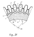
- FIGS. 21 and 22 show more particularly a step of the method according to the invention during which an internal coating 3 is formed on the internal wall of the corrugated internal envelope 1 by the technique of powder metallurgy using a container for the powder material intended to constitute the internal coating 3, the formation of this internal coating being effected by application of a hot isostatic compaction cycle.
- the external wall of the container is formed directly by the strip or internal envelope 1 while the internal wall of the container is constituted by an anvil 50 which is not consumable and removable which can be recovered after each hot isostatic compaction operation, or else by a mandrel or core soluble 50, that is to say by a non-recoverable element which undergoes chemical dissolution after an isostatic compaction operation at hot.
- the axis of the combustion chamber is identified by the reference 60.
- the useful part of the chamber has a length L2 defined by two cutting planes D1 and D2 at the level of which cutting is carried out after l 'operation of forming the internal coating 3.
- the container thus defines during the hot isostatic compaction operation a head excess length L1 and a foot excess length L3.
- the metal strips constituting the inner 1 and outer 2 ′ envelopes of the wall to be manufactured are folded over the external transverse faces of the element 50 forming a mandrel or anvil and are welded to this element 50 in zones 91, 92.
- the arrows 8 designate the isostatic pressure which is exerted on the compaction enclosure during the hot isostatic compaction operation. This pressure P is exerted both on the internal face 51 of the element 50 and on the strips constituting the envelopes 1 and 2 ′.
- At least one hole 93 is drilled in the external envelope 2 ′ at the level of each channel 7, so that only the internal envelope 1 undergoes a deformation when the pressure P is exerted to compact the internal coating 3 formed from powders , while the outer casing 2 ′ may not collapse on the inner casing 1 due to the pressure balance between the interior of the passage 7 and the outer face of the outer casing 2 ′.
- materials suitable for producing the internal coating 3 in powder metallurgy mention may be made of copper, silver, a mixture of copper and silver, a mixture of metallic powders comprising, for example copper, nickel, tungsten with dispersion of oxides such as YO2, SiO2, Al2O3, tungsten, platinum, nickel and nickel-based alloys such as N18, Astroloy, inco 625, inco 718, ceramics.
- Materials suitable for producing the external coating 5 by plasma forming are, for example, titanium and its alloys, nickel and its alloys, alloys of the M Cr AlY or MCo Cr Al Y type where M denotes nickel or cobalt.
- this can be carried out with composite materials such as SiC, or carbon-carbon, or be constituted by windings of impregnated fibers.
- a large choice of metallic materials is possible for the strips constituting the inner 1 and outer 2, 2 ′ envelopes as well as any additional envelopes 101, 201, 102, 202, 102 ′, 202 ′.
- the different envelopes 1, 2, 2 ′, 101, 102, 202, 102 ′, 202 ′ intended to define, after shaping and assembly, for example by welding or brazing in zones 8, the different fluid circulation channels 7 , 107, 207, 109, 209, can have very varied forms.
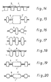
- Various possible configurations are shown in FIGS. 8 to 20, taking as an example a simple assembly of an internal envelope 1 and an external envelope 2 or 2 ′. Naturally these configurations can be applied in the same way to two additional envelopes such as 101, 102 or 102 ′ for example.
Landscapes
- Engineering & Computer Science (AREA)
- Chemical & Material Sciences (AREA)
- Combustion & Propulsion (AREA)
- Mechanical Engineering (AREA)
- General Engineering & Computer Science (AREA)
- Other Surface Treatments For Metallic Materials (AREA)
- Powder Metallurgy (AREA)
- Pressure Welding/Diffusion-Bonding (AREA)
Claims (19)
- Herstellungsverfahren für eine Brennkammerwand mit im wesentlichen longitudinalen Kanälen, insbesondere für ein Raketentriebwerk, bei dem ein erstes (1) und zweites metallisches Band (2) zusammengebaut werden, die miteinander verschweißt und so geformt sind, daß sie Wellen (11, 12; 21, 22) zwischen den Schweißnähten (8) aufweisen, um so Durchgänge (7) für ein Kühl- oder Heizfluid zu bilden, mit den Schrittena) Herstellen einer gewellten inneren Hülle (1) durch Verformung eines ersten flachen oder rohrförmigen Bandes,b) Herstellen einer äußeren metallischen Hülle (2) aus einem zweiten flachen oder rohrförmigen Band,c) Zusammensetzen und lokales Verschweißen der gewellten inneren Hülle (1) und der äußeren Hülle (2)
gekennzeichnet durch folgende Schritted) Bilden eines inneren Überzugs (3) an der Innenwand der gewellten inneren Hülle (1) durch Pulvermetallurgietechnik, wobei für das zur Bildung des inneren Überzugs (3) vorgesehene Material ein Behälter verwendet wird, dessen Außenwand direkt von der Innenwand der gewellten inneren Hülle (1) gebildet wird und dessen Innenwand aus wiederverwendbaren entfernbaren Formkörpern oder aus einem löslichen Kern gebildet wird, der nach Bildung des inneren Überzugs (3) durch Anwendung eines isostatischen Heißverdichtungszyklus durch selektives chemisches Lösen entfernt wird, unde) Bilden eines äußeren Überzugs (5) an der Außenwand der äußeren Hülle (2). - Verfahren nach Anspruch 1, dadurch gekennzeichnet, daß der äußere Überzug (5) direkt an der Außenwand der äußeren Hülle (2) durch Plasmaabscheidung von metallischen oder keramischen Pulvern gebildet wird.
- Verfahren nach Anspruch 2, dadurch gekennzeichnet, daß der durch Plasmaabscheidung gebildete äußere Überzug (5) aus einer Legierungsschicht besteht, deren Zusammensetzung über die Dicke der Legierungsschicht hinweg veränderlich ist.
- Verfahren nach einem der Ansprüche 1 bis 3, dadurch gekennzeichnet, daß eine äußere metallische Hülle (2) ohne Wellen durch einfaches Aufrollen des zweiten Bandes gebildet wird.
- Verfahren nach einem der Ansprüche 1 bis 3, dadurch gekennzeichnet, daß eine Wellen aufweisende äußere metallische Hülle (2') durch Verformung des zweiten Bandes gebildet wird.
- Verfahren nach einem der Ansprüche 1 bis 5, dadurch gekennzeichnet, daß die Wellen der inneren metallischen Hülle (1) und ggf. der äußeren metallischen Hülle (2') durch Formgebung des ersten und zweiten Bandes mit einer Hydroforming-Technik gebildet werden.
- Verfahren nach einem der Ansprüche 1 bis 5, dadurch gekennzeichnet, daß die Wellen der inneren metallischen Hülle (1) und ggf. der äußeren metallischen Hülle (2') durch ein Verfahren zur Verformung des ersten und zweiten Bandes im superplastischen Bereich gebildet werden.
- Verfahren nach einem der Ansprüche 1 bis 5, dadurch gekennzeichnet, daß die Wellen der inneren metallischen Hülle (1) und ggf. der äußeren metallischen Hülle (2') durch Formgebung des ersten und zweiten Bandes mit einem Tiefzieh- oder Biegeverfahren gebildet werden.
- Verfahren nach einem der Ansprüche 1 bis 5, dadurch gekennzeichnet, daß die Wellen der inneren metallischen Hülle (1) und ggf. der äußeren metallischen Hülle (2') durch ein Verfahren zur Verformung des ersten und zweiten Bandes nach deren Formung zu durch eine Diametralebene begrenzten Rotationshalbkörpern, Zylinder-, Kegel- oder Spitzbogensektoren gebildet werden.
- Verfahren nach einem der Ansprüche 1 bis 9, dadurch gekennzeichnet, daß die gewellte innere Hülle (1) und die äußere Hülle (2) durch lokale Schweißung mit Hilfe eines der folgenden Verfahren zusammengebaut werden: Laserschweißung, Diffusionsschweißung, Mikro-WIG-Schweißung, Löten.
- Verfahren nach einem der Ansprüche 1 bis 10, dadurch gekennzeichnet, daß durch Pulvermetallurgie mit Hilfe der Technik des löslichen Kerns oder der der entfernbaren Formkörper eine Innenwand (4) des inneren Überzugs (3) gebildet wird, die eine geriffelte, gewellte oder glatte Form aufweist.
- Verfahren nach einem der Ansprüche 1 bis 11, dadurch gekennzeichnet, daß die Endbearbeitung der Kanten und der Oberfläche der Innenwand (4) des inneren Überzugs (3) mit wenigstens einem der folgenden Verfahren durchgeführt werden: Chemische Bearbeitung und Fertigbearbeitung mit Schleifpaste unter Druck.
- Verfahren nach einem der Ansprüche 1 und 4 bis 12, dadurch gekennzeichnet, daß der äußere Überzug (5) direkt an der Außenwand der äußeren Hülle (2) durch Umgürten oder Umwickeln mit einem Verbundmaterial gebildet wird.
- Verfahren nach Anspruch 1 oder einem der Ansprüche 4 bis 12, dadurch gekennzeichnet, daß der äußere Überzug (5) direkt an der Außenwand der äußeren Hülle (2) durch Elektroabscheidung gebildet wird.
- Verfahren nach einem der Ansprüche 1 bis 14, dadurch gekennzeichnet, daß zwischen der äußeren Hülle (2) und dem äußeren Überzug (5) ein erstes zusätzliches Kühl- oder Heizsystem angeordnet wird, das eine zusätzliche gewellte innere metallische Hülle (101) und eine zusätzliche äußere metallische Hülle (102) umfaßt, die nach den obengenannten Schritten a) bis c) hergestellt und zusammengesetzt sind, um eine erste und zweite Reihe von alternierenden zusätzlichen Durchgängen (107, 109) für den Durchgang wenigstens eines Kühl- oder Heizfluids zu schaffen, ferner die zusätzliche gewellte innere Hülle (101) und die äußere Hülle (2) zusammenzusetzen und lokal zu verschweißen und den äußeren Überzug (5) an der Außenwand der zusätzlichen äußeren Hülle (102) anstatt auf der Außenwand der äußeren Hülle (2) zu bilden.
- Verfahren nach einem der Ansprüche 1 bis 14, dadurch gekennzeichnet, daß zwischen der äußeren Hülle (2) und dem äußeren Überzug (5) mehrere zusätzliche Kühl- oder Heizsysteme (100, 102) gebildet und angeordnet werden, die jeweils eine zusätzliche gewellte innere metallische Hülle (101, 201) und eine zusätzliche äußere metallische Hülle (102, 202; 102', 202') umfassen, die nach den obengenannten Schritten a) bis c) hergestellt und zusammengesetzt sind, um in jedem zusätzlichen Kühl- oder Heizsystem (100, 200) eine erste und zweite Reihe von alternierenden zusätzlichen Durchgängen (107, 109; 207, 209) für den Durchgang wenigstens eines Kühl- oder Heizfluids zu schaffen, ferner i) die äußere Hülle (2, 2') und die zusätzliche gewellte innere Hülle (101) des innersten zusätzlichen Kühl- oder Heizsystems (100) und ii) die zusätzliche gewellte innere Hülle (201) eines jeden der anderen zusätzlichen Kühl- oder Heizsysteme (200) und die zusätzliche äußere Hülle (102, 102') des unmittelbar benachbarten zusätzlichen Kühl- oder Heizsystems (100) zusammenzusetzen und lokal zu verschweißen, und den äußeren Überzug (5) an der Außenwand der äußeren zusätzlichen Hülle (202, 202') des äußersten zusätzlichen Kühl- oder Heizsystems anstatt auf der Außenwand der äußeren Hülle (2, 2') zu bilden.
- Verfahren nach Anspruch 15 oder 16, dadurch gekennzeichnet, daß zusätzlich Wellen (121, 122; 221, 222) an jeder zusätzlichen äußeren Hülle (102', 202') vor dem Zusammenbau gebildet werden, um eine wabenartige Struktur von zusätzlichen Kühl- oder Heizdurchgängen (107, 109, 207, 209) zu schaffen.
- Verfahren nach einem der Ansprüche 1 bis 17, dadurch gekennzeichnet, daß wenigstens ein Teil der zwischen der inneren Hülle (1) und der äußeren Hülle (2, 2') und ggf. zwischen den zusätzlichen inneren (101, 201) und äußeren Hüllen (102, 202, 102', 202') gebildeten Durchgängen (7, 107, 207, 109, 209) mit Granulaten oder Pulvern gefüllt werden, die katalytische Reaktionen im Kühl- oder Heizfluid hervorrufen.
- Brennkammer, hergestellt nach einem Verfahren gemäß einem der Ansprüche 1 bis 18.
Applications Claiming Priority (2)
| Application Number | Priority Date | Filing Date | Title |
|---|---|---|---|
| FR9015073A FR2669966B1 (fr) | 1990-11-30 | 1990-11-30 | Procede de fabrication de paroi de chambre de combustion, notamment pour moteur-fusee, et chambre de combustion obtenue par ce procede. |
| FR9015073 | 1990-11-30 |
Publications (2)
| Publication Number | Publication Date |
|---|---|
| EP0488858A1 EP0488858A1 (de) | 1992-06-03 |
| EP0488858B1 true EP0488858B1 (de) | 1994-11-30 |
Family
ID=9402819
Family Applications (1)
| Application Number | Title | Priority Date | Filing Date |
|---|---|---|---|
| EP91403150A Expired - Lifetime EP0488858B1 (de) | 1990-11-30 | 1991-11-22 | Herstellungsweise einer Brennkammerwand, insbesondere für einen Raketenmotor und durch diese Methode hergestellte Brennkammer |
Country Status (5)
| Country | Link |
|---|---|
| US (1) | US5233755A (de) |
| EP (1) | EP0488858B1 (de) |
| JP (1) | JP3068299B2 (de) |
| DE (1) | DE69105464T2 (de) |
| FR (1) | FR2669966B1 (de) |
Families Citing this family (59)
| Publication number | Priority date | Publication date | Assignee | Title |
|---|---|---|---|---|
| US5330092A (en) * | 1991-12-17 | 1994-07-19 | The Boeing Company | Multiple density sandwich structures and method of fabrication |
| US5501011A (en) * | 1992-05-18 | 1996-03-26 | Societe Europeenne De Propulsion | Method of manufacture of an enclosure containing hot gases cooled by transportation, in particular the thrust chamber of a rocket engine |
| DE4301041C1 (de) * | 1993-01-16 | 1994-04-28 | Deutsche Aerospace | Verfahren zur Herstellung einer fluidgekühlten Wand in Röhrchenverbundbauweise |
| US5473817A (en) * | 1993-12-21 | 1995-12-12 | United Technologies Corporation | Method of making cooled rocket combustion chamber construction |
| US5557927A (en) * | 1994-02-07 | 1996-09-24 | Rockwell International Corporation | Blanching resistant coating for copper alloy rocket engine main chamber lining |
| FR2716398B1 (fr) * | 1994-02-22 | 1996-05-24 | Seva | Procédé de fabrication d'un élément d'enceinte de fluide. |
| DE4437524C2 (de) * | 1994-10-20 | 1997-04-24 | Kunkel Klaus Dr Ing | Verfahren zum Betreiben eines nach dem Rückstoßprinzip arbeitenden Antriebes eines Flugkörpers sowie Flugkörperantrieb |
| US5546656A (en) * | 1994-11-30 | 1996-08-20 | United Technologies Corporation | Fabrication of rocket thrust chambers |
| FR2733581B1 (fr) * | 1995-04-27 | 1997-07-18 | Europ Propulsion | Enceinte de combustion avec refroidissement par transpiration |
| US5832719A (en) * | 1995-12-18 | 1998-11-10 | United Technologies Corporation | Rocket thrust chamber |
| US5720451A (en) * | 1995-12-19 | 1998-02-24 | Trw Inc. | High temperature thrust chamber for spacecraft |
| US6393828B1 (en) † | 1997-07-21 | 2002-05-28 | General Electric Company | Protective coatings for turbine combustion components |
| SE512942C2 (sv) * | 1998-10-02 | 2000-06-12 | Volvo Aero Corp | Förfarande för tillverkning av utloppsmunstycken för raketmotorer |
| US6134782A (en) * | 1998-11-30 | 2000-10-24 | United Technologies Corporation | Method of forming a rocket thrust chamber |
| US6131280A (en) * | 1998-11-30 | 2000-10-17 | United Technologies Corporation | Method of repairing a rocket thrust chamber |
| RU2158666C2 (ru) * | 1999-02-04 | 2000-11-10 | Открытое акционерное общество НПО Энергомаш им. акад. В.П. Глушко | Способ изготовления сварно-паяной конструкции |
| RU2158667C1 (ru) * | 1999-03-01 | 2000-11-10 | Открытое акционерное общество НПО Энергомаш им. акад. В.П. Глушко | Способ изготовления сварно-паяной конструкции газогенератора |
| US6421998B1 (en) * | 2000-06-13 | 2002-07-23 | The Boeing Company | Thruster device responsive to solar radiation |
| DE10054333B4 (de) * | 2000-11-02 | 2006-11-30 | Eads Space Transportation Gmbh | Brennkammer mit erhöhtem Wärmeeintrag in eine Kühleinrichtung |
| RU2273756C2 (ru) * | 2001-01-11 | 2006-04-10 | Вольво Аэро Корпорейшн | Элемент ракетного двигателя и способ изготовления такого элемента ракетного двигателя |
| US6907920B2 (en) * | 2002-01-29 | 2005-06-21 | United Technologies Corporation | Heat exchanger panel |
| KR100450699B1 (ko) * | 2002-05-06 | 2004-10-01 | 주식회사 로템 | 액체로켓엔진용 연소기 제조 방법 |
| RU2303155C2 (ru) * | 2002-05-28 | 2007-07-20 | Вольво Аэро Корпорейшн | Конструкция стенки и элемент реактивного двигателя космического аппарата |
| DE10237381B4 (de) * | 2002-08-12 | 2005-06-23 | Eads Space Transportation Gmbh | Brennkammerstruktur und Verfahren zu deren Herstellung |
| KR100514414B1 (ko) * | 2003-11-20 | 2005-09-09 | 주식회사 하이닉스반도체 | 지연 동기 루프 |
| US20050189097A1 (en) * | 2004-03-01 | 2005-09-01 | The Boeing Company | Formed sheet heat exchanger |
| US7493691B2 (en) * | 2004-05-20 | 2009-02-24 | Honeywell International Inc. | Co-molding metallic-lined phenolic components |
| US7219505B2 (en) * | 2004-10-22 | 2007-05-22 | York International Corporation | Control stability system for moist air dehumidification units and method of operation |
| US7596940B2 (en) * | 2005-03-22 | 2009-10-06 | Pratt & Whitney Rocketdyne, Inc. | Rocket engine nozzle and method of fabricating a rocket engine nozzle using pressure brazing |
| ES2350847T3 (es) * | 2005-09-06 | 2011-01-27 | Volvo Aero Corporation | Procedimiento para la fabricación de una estructura de pared de un motor. |
| DE102006021539A1 (de) * | 2006-05-08 | 2007-11-15 | Eads Space Transportation Gmbh | Verfahren zur Herstellung von Bauteilen für den Raketenbau |
| FR2945581B1 (fr) * | 2009-05-15 | 2014-05-02 | Snecma | Divergent de moteur pour un vehicule capable de se deplacer dans l'air ou dans l'espace et son procede de fabrication. |
| FR2945580B1 (fr) * | 2009-05-15 | 2015-12-25 | Snecma | Chambre de combustion de moteur pour un vehicule capable de se deplacer dans l'air ou dans l'espace et son procede de fabrication. |
| US20120180753A1 (en) * | 2011-01-13 | 2012-07-19 | GM Global Technology Operations LLC | Active thermal shield and diverter |
| FR3004368B1 (fr) * | 2013-04-15 | 2015-09-25 | Aircelle Sa | Brasage sans outillage |
| CN103464856B (zh) * | 2013-09-25 | 2015-10-14 | 贵州凯星液力传动机械有限公司 | 一种不锈钢喷注器的加工方法 |
| DE102014100345B4 (de) * | 2014-01-14 | 2015-09-03 | Deutsches Zentrum für Luft- und Raumfahrt e.V. | Verfahren zur Herstellung einer Schubkammervorrichtung, Schubkammervorrichtung und Raketentriebwerk |
| KR101563708B1 (ko) * | 2014-09-30 | 2015-10-27 | 우신공업 주식회사 | 자동차용 필터파이프의 제조방법 및 이에 의해 제조된 자동차용 필터파이프 |
| JP5823069B1 (ja) * | 2015-01-23 | 2015-11-25 | 三菱重工業株式会社 | ロケットエンジンの燃焼器の製造方法、ロケットエンジンの燃焼器、および、ロケットエンジン |
| JP6664786B2 (ja) * | 2015-07-16 | 2020-03-13 | 国立研究開発法人宇宙航空研究開発機構 | ロケット用再生冷却ノズルの製造方法 |
| JP2019015180A (ja) * | 2017-07-03 | 2019-01-31 | 国立研究開発法人宇宙航空研究開発機構 | 燃焼室の冷却機構 |
| JP7005744B2 (ja) * | 2017-08-04 | 2022-01-24 | ビ-エイイ- システムズ パブリック リミテッド カンパニ- | 粉末熱間等方圧加圧 |
| PL3597897T3 (pl) * | 2018-07-17 | 2024-06-24 | Arianegroup Gmbh | Konstrukcja komory spalania, szczególnie dla silników rakietowych |
| DE102019132013A1 (de) * | 2019-11-26 | 2021-05-27 | Bayerische Motoren Werke Aktiengesellschaft | Wärmetauschereinrichtung für ein Kraftfahrzeug, Verfahren zum Betreiben einer Wärmetauschereinrichtung sowie Verfahren zum Herstellen einer Wärmetauschereinrichtung |
| US11236902B2 (en) * | 2020-04-27 | 2022-02-01 | Rheem Manufacturing Company | Frustoconical combustion chamber for a fluid heating device and methods for making the same |
| US12415229B2 (en) | 2020-07-29 | 2025-09-16 | Blue Origin Manufacturing, LLC | Friction stir welding systems and methods |
| DE102020124542A1 (de) * | 2020-09-21 | 2022-03-24 | Arianegroup Gmbh | Brennkammer mit schwingungsdämpfender Innenwandform und Verfahren zum Herstellen eines Brennkammerabschnitts |
| JP7545280B2 (ja) * | 2020-09-29 | 2024-09-04 | ダイキョーニシカワ株式会社 | 電磁波遮蔽パネルとその製造方法 |
| CN112338448A (zh) * | 2020-10-23 | 2021-02-09 | 西安远航真空钎焊技术有限公司 | 波纹片夹层隔板组件的制备方法 |
| KR102468746B1 (ko) * | 2020-11-18 | 2022-11-18 | 한국항공우주연구원 | 열교환 구조를 포함하는 연소기 및 이를 포함하는 로켓 |
| CN113565652B (zh) * | 2021-07-27 | 2022-08-19 | 中国人民解放军国防科技大学 | 一种多层固定的高温流体通道 |
| CN114645803B (zh) * | 2022-03-17 | 2024-06-25 | 北京航空航天大学 | 一种复合材料缠绕再生冷却推力室及加工工艺 |
| US12172229B2 (en) | 2023-03-30 | 2024-12-24 | Blue Origin, Llc | Friction stir additive manufacturing devices and methods for forming in-situ rivets |
| US12246392B2 (en) | 2023-03-30 | 2025-03-11 | Blue Origin Manufacturing, LLC | Deposition head for friction stir additive manufacturing devices and methods |
| US12140109B2 (en) | 2023-03-30 | 2024-11-12 | Blue Origin, Llc | Transpiration-cooled systems having permeable and non-permeable portions |
| CN116857086A (zh) * | 2023-07-05 | 2023-10-10 | 西安航天动力研究所 | 一种推力室喉部连接结构及其加工方法 |
| US12383975B2 (en) * | 2023-08-03 | 2025-08-12 | Blue Origin Manufacturing, LLC | Friction stir additive manufacturing formed parts and structures with integrated passages |
| US12303994B2 (en) | 2023-08-03 | 2025-05-20 | Blue Origin Manufacturing, LLC | Friction stir additive manufacturing formed parts and structures with integrated passages |
| US12589446B2 (en) | 2023-12-12 | 2026-03-31 | Blue Origin Manufacturing, LLC | Wire-feed friction stir additive manufacturing systems, devices, and methods |
Family Cites Families (12)
| Publication number | Priority date | Publication date | Assignee | Title |
|---|---|---|---|---|
| US2968918A (en) * | 1949-08-22 | 1961-01-24 | California Inst Res Found | Rocket motor shell construction |
| US2892253A (en) * | 1953-03-02 | 1959-06-30 | Hugh A Hutchins | Method for making jet tubes |
| GB937695A (en) * | 1961-12-22 | 1963-09-25 | Ludwig Bolkow | Process for the manufacture of liquid cooled combustion chambers for rockets |
| US3182448A (en) * | 1960-06-22 | 1965-05-11 | Thiokol Chemical Corp | Rocket motor construction |
| US3235947A (en) * | 1961-12-22 | 1966-02-22 | Bolkow Gmbh | Method for making a combustion chamber |
| US3208132A (en) * | 1962-04-13 | 1965-09-28 | William J D Escher | Method of making a multi-walled chamber |
| US3289943A (en) * | 1962-08-17 | 1966-12-06 | Westinghouse Electric Corp | Thermal barrier for thrust vehicle nozzle |
| US3254395A (en) * | 1963-01-04 | 1966-06-07 | Edward F Baehr | Method of making a rocket motor casing |
| US3460759A (en) * | 1967-03-07 | 1969-08-12 | Nasa | Combustion chamber |
| DE1751180A1 (de) * | 1968-04-18 | 1971-04-29 | Messerschmitt Boelkow Blohm | Ausbildung und Anordnung eines Zulaufringes oder Ablaufsammelringes fuer Schubduesen oder Brennkammern von Raketentriebwerken,insbesondere Fluessigkeitsraketentriebwerken |
| DE2015024B2 (de) * | 1970-03-28 | 1971-10-14 | Messerschmitt Bolkow Blohm GmbH, 8000 München | Verfahren zur herstellung von regenerativ gekuehlten brenn kammern und oder schubduesen |
| US4841723A (en) * | 1986-10-14 | 1989-06-27 | General Electric Company | Multiple-propellant air vehicle and propulsion system |
-
1990
- 1990-11-30 FR FR9015073A patent/FR2669966B1/fr not_active Expired - Fee Related
-
1991
- 1991-11-21 US US07/795,833 patent/US5233755A/en not_active Expired - Lifetime
- 1991-11-22 EP EP91403150A patent/EP0488858B1/de not_active Expired - Lifetime
- 1991-11-22 DE DE69105464T patent/DE69105464T2/de not_active Expired - Fee Related
- 1991-11-30 JP JP3356102A patent/JP3068299B2/ja not_active Expired - Fee Related
Also Published As
| Publication number | Publication date |
|---|---|
| DE69105464T2 (de) | 1995-04-20 |
| FR2669966A1 (fr) | 1992-06-05 |
| JPH04301168A (ja) | 1992-10-23 |
| EP0488858A1 (de) | 1992-06-03 |
| DE69105464D1 (de) | 1995-01-12 |
| FR2669966B1 (fr) | 1993-03-26 |
| JP3068299B2 (ja) | 2000-07-24 |
| US5233755A (en) | 1993-08-10 |
Similar Documents
| Publication | Publication Date | Title |
|---|---|---|
| EP0488858B1 (de) | Herstellungsweise einer Brennkammerwand, insbesondere für einen Raketenmotor und durch diese Methode hergestellte Brennkammer | |
| EP0571254B1 (de) | Oberflächengekühlte Brennkammer | |
| EP2994711B1 (de) | Verfahren zur herstellung eines wärmetauschermoduls mit mindestens zwei strömungskreisläufen | |
| EP1404973B1 (de) | Verfahren zu herstellung eines stators für eine exzenterschneckenpumpe und sich daraus ergebender stator | |
| FR2539479A1 (fr) | Structure de joint alveolee | |
| WO2017060600A1 (fr) | Procede de fabrication additive comprenant une etape de pressage isostatique a chaud | |
| FR2733581A1 (fr) | Enceinte de combustion avec refroidissement par transpiration | |
| FR2776215A1 (fr) | Procede de fabrication d'un circuit regeneratif a fort flux thermique, notamment pour chambre de combustion de moteur-fusee | |
| CA2710451C (fr) | Procede de fabrication d'une piece metallique renforcee de fibres ceramiques | |
| FR2706948A1 (de) | ||
| EP3469206B1 (de) | Raketentriebwerkbrennkammer mit rippen mit variabler zusammensetzung | |
| EP3833854B1 (de) | Innengehäuse einer turbomaschine mit verbesserter wärmeisolierung | |
| WO2020127300A1 (fr) | Regenerateur et procede de fabrication d'un tel regenerateur | |
| EP1682463B1 (de) | Verfahren zur herstellung von verbundkörpern aus blähgraphit und vermiculit | |
| EP4166881B1 (de) | Modul zur herstellung eines wärmerohrs mit kapillarpumpe mit wiedereintrittsnuten | |
| EP3657113B1 (de) | Herstellungsverfahren eines wärmetauschermoduls mit mindestens einem fluid-umwälzkreislauf | |
| EP4433769A1 (de) | Einteiliger wärmetauscher | |
| FR2945580A1 (fr) | Chambre de combustion de moteur pour un vehicule capable de se deplacer dans l'air ou dans l'espace et son procede de fabrication. | |
| FR2541152A1 (fr) | Procede pour la realisation de corps metalliques composites | |
| FR3119670A1 (fr) | Echangeur thermique et son procédé de fabrication | |
| FR2945581A1 (fr) | Divergent de moteur pour un vehicule capable de se deplacer dans l'air ou dans l'espace et son procede de fabrication. | |
| FR3000192A1 (fr) | Charge militaire a eclats et procede de fabrication | |
| WO2023088841A1 (fr) | Titre : cellule thermoacoustique comprenant une enveloppe en matériau composite | |
| FR3099239A1 (fr) | Echangeur de chaleur notamment pour véhicule automobile et procédé de fabrication d’un tel échangeur de chaleur | |
| EP4004472A1 (de) | Wärmetauscher, insbesondere für ein kraftfahrzeug, und verfahren zur herstellung eines solchen wärmetauschers |
Legal Events
| Date | Code | Title | Description |
|---|---|---|---|
| PUAI | Public reference made under article 153(3) epc to a published international application that has entered the european phase |
Free format text: ORIGINAL CODE: 0009012 |
|
| AK | Designated contracting states |
Kind code of ref document: A1 Designated state(s): DE GB IT SE |
|
| RAP3 | Party data changed (applicant data changed or rights of an application transferred) |
Owner name: SOCIETE EUROPEENNE DE PROPULSION |
|
| 17P | Request for examination filed |
Effective date: 19921112 |
|
| 17Q | First examination report despatched |
Effective date: 19940110 |
|
| GRAA | (expected) grant |
Free format text: ORIGINAL CODE: 0009210 |
|
| AK | Designated contracting states |
Kind code of ref document: B1 Designated state(s): DE GB IT SE |
|
| PG25 | Lapsed in a contracting state [announced via postgrant information from national office to epo] |
Ref country code: IT Free format text: LAPSE BECAUSE OF FAILURE TO SUBMIT A TRANSLATION OF THE DESCRIPTION OR TO PAY THE FEE WITHIN THE PRE;WARNING: LAPSES OF ITALIAN PATENTS WITH EFFECTIVE DATE BEFORE 2007 MAY HAVE OCCURRED AT ANY TIME BEFORE 2007. THE CORRECT EFFECTIVE DATE MAY BE DIFFERENT FROM THE ONE RECORDED.SCRIBED TIME-LIMIT Effective date: 19941130 Ref country code: GB Effective date: 19941130 |
|
| REF | Corresponds to: |
Ref document number: 69105464 Country of ref document: DE Date of ref document: 19950112 |
|
| GBV | Gb: ep patent (uk) treated as always having been void in accordance with gb section 77(7)/1977 [no translation filed] |
Effective date: 19941130 |
|
| PLBE | No opposition filed within time limit |
Free format text: ORIGINAL CODE: 0009261 |
|
| STAA | Information on the status of an ep patent application or granted ep patent |
Free format text: STATUS: NO OPPOSITION FILED WITHIN TIME LIMIT |
|
| 26N | No opposition filed | ||
| PGFP | Annual fee paid to national office [announced via postgrant information from national office to epo] |
Ref country code: DE Payment date: 20071113 Year of fee payment: 17 |
|
| PGFP | Annual fee paid to national office [announced via postgrant information from national office to epo] |
Ref country code: SE Payment date: 20071025 Year of fee payment: 17 |
|
| EUG | Se: european patent has lapsed | ||
| PG25 | Lapsed in a contracting state [announced via postgrant information from national office to epo] |
Ref country code: DE Free format text: LAPSE BECAUSE OF NON-PAYMENT OF DUE FEES Effective date: 20090603 |
|
| PG25 | Lapsed in a contracting state [announced via postgrant information from national office to epo] |
Ref country code: SE Free format text: LAPSE BECAUSE OF NON-PAYMENT OF DUE FEES Effective date: 20081123 |