EP0488923A2 - Selbstklebende Latte für Täfelung, Parkettfussboden oder ähnliche fugendichte Verkleidungsmontage und Zusammensetzungsverfahren einer aus solchen Latten bestehenden Verkleidung - Google Patents
Selbstklebende Latte für Täfelung, Parkettfussboden oder ähnliche fugendichte Verkleidungsmontage und Zusammensetzungsverfahren einer aus solchen Latten bestehenden Verkleidung Download PDFInfo
- Publication number
- EP0488923A2 EP0488923A2 EP91450011A EP91450011A EP0488923A2 EP 0488923 A2 EP0488923 A2 EP 0488923A2 EP 91450011 A EP91450011 A EP 91450011A EP 91450011 A EP91450011 A EP 91450011A EP 0488923 A2 EP0488923 A2 EP 0488923A2
- Authority
- EP
- European Patent Office
- Prior art keywords
- facing
- rebate
- slat
- longitudinal
- slats
- Prior art date
- Legal status (The legal status is an assumption and is not a legal conclusion. Google has not performed a legal analysis and makes no representation as to the accuracy of the status listed.)
- Withdrawn
Links
Images

Classifications
-
- E—FIXED CONSTRUCTIONS
- E04—BUILDING
- E04F—FINISHING WORK ON BUILDINGS, e.g. STAIRS, FLOORS
- E04F15/00—Flooring
- E04F15/02—Flooring or floor layers composed of a number of similar elements
- E04F15/02005—Construction of joints, e.g. dividing strips
- E04F15/02033—Joints with beveled or recessed upper edges
-
- E—FIXED CONSTRUCTIONS
- E04—BUILDING
- E04F—FINISHING WORK ON BUILDINGS, e.g. STAIRS, FLOORS
- E04F13/00—Coverings or linings, e.g. for walls or ceilings
- E04F13/07—Coverings or linings, e.g. for walls or ceilings composed of covering or lining elements; Sub-structures therefor; Fastening means therefor
- E04F13/08—Coverings or linings, e.g. for walls or ceilings composed of covering or lining elements; Sub-structures therefor; Fastening means therefor composed of a plurality of similar covering or lining elements
- E04F13/10—Coverings or linings, e.g. for walls or ceilings composed of covering or lining elements; Sub-structures therefor; Fastening means therefor composed of a plurality of similar covering or lining elements of wood or with an outer layer of wood
-
- E—FIXED CONSTRUCTIONS
- E04—BUILDING
- E04F—FINISHING WORK ON BUILDINGS, e.g. STAIRS, FLOORS
- E04F15/00—Flooring
- E04F15/02—Flooring or floor layers composed of a number of similar elements
- E04F15/0215—Flooring or floor layers composed of a number of similar elements specially adapted for being adhesively fixed to an underlayer; Fastening means therefor; Fixing by means of plastics materials hardening after application
-
- E—FIXED CONSTRUCTIONS
- E04—BUILDING
- E04F—FINISHING WORK ON BUILDINGS, e.g. STAIRS, FLOORS
- E04F15/00—Flooring
- E04F15/02—Flooring or floor layers composed of a number of similar elements
- E04F15/04—Flooring or floor layers composed of a number of similar elements only of wood or with a top layer of wood, e.g. with wooden or metal connecting members
-
- E—FIXED CONSTRUCTIONS
- E04—BUILDING
- E04F—FINISHING WORK ON BUILDINGS, e.g. STAIRS, FLOORS
- E04F2201/00—Joining sheets or plates or panels
- E04F2201/01—Joining sheets, plates or panels with edges in abutting relationship
- E04F2201/0123—Joining sheets, plates or panels with edges in abutting relationship by moving the sheets, plates or panels parallel to the abutting edges
-
- E—FIXED CONSTRUCTIONS
- E04—BUILDING
- E04F—FINISHING WORK ON BUILDINGS, e.g. STAIRS, FLOORS
- E04F2201/00—Joining sheets or plates or panels
- E04F2201/07—Joining sheets or plates or panels with connections using a special adhesive material
Definitions
- the present invention generally relates to a covering composed of slats with joined joints such as a paneling, parquet or other, and applies more particularly to such slats, as well as to a method of mounting a covering with these slats.
- Laths have been known for a long time for producing a paneling, a parquet or a batten, to be applied to a wall such as for example a partition, a floor or a ceiling.
- these slats are made of wood from species such as Austin pine, oak or others.
- These slats of the prior art are generally rectangular in shape and have on one of their longitudinal edges or sides a tongue, and on the other edge a groove, to allow a joint assembly of widening of several slats, by engagement. the tongue of one slat in the groove of the other.
- the known slats are difficult to install, since they are rigid, of considerable length and that they must be fixed, for example, on battens using spikes, staples or clips.
- the presence of grooves and tongues makes these slats heavy, thick and expensive, because these parts require an excess of raw material as well as significant machining to obtain them.
- the present invention aims to solve the drawbacks which have just been mentioned, as well as others, by proposing an economical, space-saving and light batten, which allows an easy and precise assembly by the realization of a coating.
- a coating such as paneling, parquet or other, using slats which can be quickly attached and which can preferably be purchased, for example in batches ready to install.
- the subject of the present invention is a slat for a covering with a joined assembly such as a paneling, parquet or other, this slat being characterized in that it is self-adhesive on its face on the opposite side.
- the advantage of such a self-adhesive slat is that it allows easy and rapid attachment to any support surface, such as a wall for example.
- This slat is further characterized in that in the state of product awaiting installation, the glued side is covered with a protective strip, so as to facilitate the handling of the slats while preserving the adhesive qualities of the adhesive applied. on these.
- the batten according to the invention is characterized in that the adhesive layer is applied to a sealing or insulating coating, such as for example a varnish, covering the facing face. Thanks to this coating, any migration of the adhesive towards the interior of the slat, as well as any interference of sap or moisture in the fixing adhesive are made impossible.
- a sealing or insulating coating such as for example a varnish
- the slat has a generally rectangular shape and is characterized in that it is provided, on each of its two opposite longitudinal edges, with an assembly rebate joined to a neighboring slat, one of the rebates being turned on the facing side, and the other being turned on the side of the facing.
- the presence of these longitudinal rebates has the advantage, on the one hand, of making fast and precise the positioning and mounting of the slats with respect to each other, and on the other hand, of reducing the quantity of raw material necessary for the obtaining a batten and therefore reducing its weight, its rigidity and its cost.
- the batten is further characterized in that, on at least one of the opposite transverse edges, there is provided a rebate turned towards the side of the facing.
- the invention is characterized in that the longitudinal rebate on the facing side forms an obtuse or right dihedral angle, while the rebates formed on the side of the facing are in a dihedral angle, preferably straight.
- edges provided with a rebate on the facing side are chamfered on the facing side or not chamfered depending on the type of coating to be produced.
- the batten is further characterized in that the longitudinal rebate on the side the facing stops at a distance from the transverse edges which is equal to the width of the corresponding transverse rabbet, the longitudinal rabbet on the opposite side having a height substantially greater than that of the projecting part formed at the edge opposite by the rabbet on the facing side.
- the thickness between and opposite is from 2 to 27 mm and is preferably 5 mm for a paneling.
- the mounting of a covering such as a paneling is characterized in that after the installation of the first self-adhesive slat, the protective strip is removed from the next slat and the latter is positioned precisely relative to the previously installed slat, by sliding guide of its longitudinal edge covering on the longitudinal rebate covered with the previous slat, before fixing by gluing of the slat thus positioned.
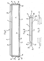
- a slat 1 for paneling, parquet, batten or the like generally has a rectangular shape. It goes without saying that, depending on the use to be made of it, the dimensions in length, width or thickness of the batten 1 can be chosen differently from those of the batten illustrated in the figures, which is only an example. for carrying out the invention, given to facilitate understanding thereof, and which cannot be considered in such a way as to limit the invention.
- facing face usually the face of the slat 1 which is intended to be visible, that is to say the face 2 shown in FIG. 1, is called “facing face”.
- the slats commonly used are obtained by machining wooden boards from various species, such as Austin pine, oak or others.
- the slats of the prior art for example a paneling with joined assembly, are fixed on a wooden frame made up of cleats, using nails, clips or staples. Such a fixing is tedious and presents risks of damaging the slats which it is desired to pose.
- the batten 1 according to the invention is self-adhesive on its counterpart face.
- a layer of glue (not shown) is applied to the opposite side 3 of the slat.
- the adhesive used may be of a different composition.
- acrylic adhesives or those of the type sold under the names such as "butyl”, “holt-melt”, can be used, as the case may be.
- the adhesive layer is applied to a sealing or insulating coating such as a varnish, for example, covering the facing face 3 of the batten 1.
- a sealing or insulating coating such as a varnish, for example, covering the facing face 3 of the batten 1.
- a sealing or insulating coating such as a varnish, for example, covering the facing face 3 of the batten 1.
- This coating forms an insulation against moisture coming from the slat or from the exterior, such as sap residue.
- the coated counterpart 3 receives the glue in the form of protruding streaks 20, the latter generally extending in the longitudinal direction of the slat, the use of glue streaks 20 having the advantage of compensating for possible flatness faults support, such as a wall for example.
- the glued side 3 is covered with a removable protective strip 4, shown in dotted lines in FIG. 2, at the start of detachment when only one of its corners is separated from the glue film. Thanks to the presence of this protective strip 4, the slat 1 can be handled and stored before installation without having to worry about damaging the adhesive layer.
- the slat 1 has two edges or longitudinal sides 5 and 6 which are opposite to each other. Each of these edges 5 and 6 is respectively provided with a rabbet 7, 8. These rabbets 7 and 8 allow a joined assembly of widening to a neighboring slat.
- the rabbet 7 of the edge 5 of the batten 1 is turned towards the side of the facing 2 and has the shape of a obtuse dihedral angle with a longitudinal edge 7b, as visible on the left in FIG. 2 in particular.
- the rabbet 8 of the edge 6 is in turn turned towards the side 3 of the batten 1 and has the shape of a substantially straight dihedral angle. It goes without saying that other similar shapes can be adopted for the longitudinal rebates.
- the longitudinal rebate 8 which is formed on the face 3 of the lath 1 opposite has a height substantially greater than that of the longitudinal part or end 9 which is formed by the rebate 7.
- the spacing formed by the rebate 8, namely the height of the edge 8a visible in FIG. 2 is greater than the thickness of the part 9 so that during the assembly of several slats 1, there is a clearance between the upper or covered surface 7a of the rebate 7 and the lower or covering surface 8b of the rebate 8 of another identical batten.
- this game (not shown) allows greatly simplified mounting of the slats according to the invention.
- the slat 1 has, at each of its lateral ends, opposite transverse edges or sides 10 and 11 which extend substantially at right angles to the edges 5 and 6.
- the transverse edges 10 and 11 are respectively provided with rebates 12 and 13, which are oriented so as to be on the side of the facing 3 and respectively lead to each longitudinal end of the rebate 8.
- the rebates 12 and 13 have the form of acute dihedral angles and have a height substantially equal to the thickness of the part 9. Consequently, the assembly clearance explained above is highlighted.
- said rebates 12 and 13 may advantageously have a height equal to the height of the longitudinal rabbet 8 and as shown in FIGS.
- the part 9 formed by the rebate 7 on the facing side 2 stops at a distance from the transverse edges 10 and 11 which is equal to the width of the corresponding transverse rebate 8, 9.
- the thickness of the batten 1 between the facing and the counterpart is between 2 and 27 mm, depending on the use to which this batten is intended.
- a slat 1 intended for producing a paneling is substantially 5 mm. It is therefore noted that in accordance with the invention and by replacing the tongues and grooves of the prior art with the rebates described above, it is possible to significantly reduce the thickness of the slat 1, so that the latter can then have improved longitudinal flexibility and lightness properties, which for example favor the installation of paneling on a surface whose flatness is not perfect.
- edges 6, 10 and 11 which are provided on their opposite side 3 with the rebates 8, 12 and 13, each have a chamfer of the facing side 2 of the slat 1.
- These chamfers 15, 16 and 17 are respectively machined on the edges 6, 10 and 11, at an angle substantially of 135 ° relative to the facing 2.
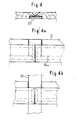
- the protective strip 4 is removed from the next slat 1B.
- the next batten can be placed either in widening or at an angle to the first batten 1A.
- the next slat 1B is positioned precisely relative to the previous slat laid 1A, by sliding guide of its longitudinal edge 6 called to cover the protruding part 9, on the longitudinal rebate 7 known as the rebate covered with the preceding slat 1A.
- the adhesive part of its backing 3 is applied to the surface S so as to fix this batten 1B definitively by gluing.
- This is how the usefulness of the assembly set described above comes out and which allows, thanks to the height of the surface 8a of the rebate 8 which is greater than the thickness of the part 9, to apply easily and completely. the glued side 3 of the slat 1B.
- this assembly play also makes it possible to compensate for a defect in the flatness of the surface S. It is therefore understood that, thanks to the invention, it is possible to apply a coating formed of slats on the same surface S whose flatness is relative, without having to resort to a frame such as for example a lattice of battens.
- the slat as described and illustrated in the figures has, in addition to the advantages already explained, that of being able to present a compact, light and practical shape, thanks to which the slats can be sold, for example in batches, in a non-specialized store. .
- the presence of an adhesive face protected by a detachable protective strip further adds to the ease of storage and use of such slats, making the tools necessary for their installation particularly simple, since it is no longer essential to use nails, staples or other fixing means known up to now.
- the slats as shown in Figure 3, and in particular the transverse sides, 10 and 11 may not be provided with chamfers 16, 17, as well as the longitudinal edges 5 and 6 at the rebate 7 , the latter having a substantially right dihedral angle, the chamfer 15 of the edge 6 being eliminated.
Landscapes
- Engineering & Computer Science (AREA)
- Architecture (AREA)
- Civil Engineering (AREA)
- Structural Engineering (AREA)
- Life Sciences & Earth Sciences (AREA)
- Wood Science & Technology (AREA)
- Finishing Walls (AREA)
Applications Claiming Priority (2)
| Application Number | Priority Date | Filing Date | Title |
|---|---|---|---|
| FR9012683A FR2667894A1 (fr) | 1990-10-15 | 1990-10-15 | Latte autocollante pour lambris, parquet ou revetement a assemblage jointif analogue, et procede de montage d'un revetement compose de telles lattes. |
| FR9012683 | 1990-10-15 |
Publications (2)
| Publication Number | Publication Date |
|---|---|
| EP0488923A2 true EP0488923A2 (de) | 1992-06-03 |
| EP0488923A3 EP0488923A3 (en) | 1992-10-07 |
Family
ID=9401214
Family Applications (1)
| Application Number | Title | Priority Date | Filing Date |
|---|---|---|---|
| EP19910450011 Withdrawn EP0488923A3 (en) | 1990-10-15 | 1991-10-15 | Self-adhesive lath for panelling, flooring or for coverings with similar edge to edge joining, and method of fitting on a covering composed of such laths |
Country Status (2)
| Country | Link |
|---|---|
| EP (1) | EP0488923A3 (de) |
| FR (1) | FR2667894A1 (de) |
Cited By (2)
| Publication number | Priority date | Publication date | Assignee | Title |
|---|---|---|---|---|
| US5593854A (en) * | 1994-02-16 | 1997-01-14 | Becton Dickinson And Company | Data analysis method for use with fluorescent bacterial sensors |
| EP4446517A1 (de) * | 2023-04-14 | 2024-10-16 | Flooring Technologies Ltd. | Fussbodenbelag aus in ihrem aufbau identischen paneelen und paneel |
Family Cites Families (5)
| Publication number | Priority date | Publication date | Assignee | Title |
|---|---|---|---|---|
| BE498361A (de) * | ||||
| US2110729A (en) * | 1933-01-03 | 1938-03-08 | Certain Teed Prod Corp | Construction material |
| US3385743A (en) * | 1965-04-05 | 1968-05-28 | Richard W. Backberg | Self-adhering surface finish laminate |
| US4261152A (en) * | 1979-09-24 | 1981-04-14 | Champion International Corporation | Multi-lap siding with beaded edge |
| DE3631390A1 (de) * | 1986-05-27 | 1987-12-03 | Edwin Kurz | Fliese |
-
1990
- 1990-10-15 FR FR9012683A patent/FR2667894A1/fr not_active Withdrawn
-
1991
- 1991-10-15 EP EP19910450011 patent/EP0488923A3/fr not_active Withdrawn
Cited By (3)
| Publication number | Priority date | Publication date | Assignee | Title |
|---|---|---|---|---|
| US5593854A (en) * | 1994-02-16 | 1997-01-14 | Becton Dickinson And Company | Data analysis method for use with fluorescent bacterial sensors |
| EP4446517A1 (de) * | 2023-04-14 | 2024-10-16 | Flooring Technologies Ltd. | Fussbodenbelag aus in ihrem aufbau identischen paneelen und paneel |
| WO2024213721A1 (de) * | 2023-04-14 | 2024-10-17 | Flooring Technologies Ltd. | FUßBODENBELAG AUS IN IHREM AUFBAU IDENTISCHEN PANEELEN UND PANEEL |
Also Published As
| Publication number | Publication date |
|---|---|
| FR2667894A1 (fr) | 1992-04-17 |
| EP0488923A3 (en) | 1992-10-07 |
Similar Documents
| Publication | Publication Date | Title |
|---|---|---|
| EP1440214B1 (de) | Vorrichtung zum zusammenfügen von den rändern von platten | |
| WO2010037938A2 (fr) | Procede de pose de panneaux sandwich | |
| FR2759111A1 (fr) | Dispositif pour l'assemblage de profiles d'un chassis de porte, fenetre ou analogue | |
| FR2808822A1 (fr) | Dispositif d'assemblage des bords longitudinaux de panneaux, lattes ou lambris, a repartition de forces | |
| EP1282753A1 (de) | Befestigungsvorrichtung für die längsränder von platten, latten oder wandverkleidungen mit kraftverteilung | |
| BE1019657A3 (fr) | Ensemble de finition pour surfaces disjointes, comportant un profil de jonction separable en deux modules aptes a former des profils d'arret. | |
| FR2605663A1 (fr) | Perfectionnement aux plinthes et elements de finition analogues du type a pose par clipsage | |
| FR2667894A1 (fr) | Latte autocollante pour lambris, parquet ou revetement a assemblage jointif analogue, et procede de montage d'un revetement compose de telles lattes. | |
| FR2931494A1 (fr) | Mur a coffrage integre | |
| FR2552804A1 (fr) | Panneau prefabrique pour le revetement de parois, procedes de fabrication et de mise en oeuvre, et plaquettes en terre cuite pour la realisation desdits panneaux | |
| FR2746127A1 (fr) | Profil d'assemblage pour lames de parquet | |
| FR3065980B1 (fr) | Systeme d’habillage d’un bord d'ouverture dans une cloison | |
| FR3091717A1 (fr) | Structure d’habillage pour porte | |
| FR2795802A1 (fr) | Dispositif de liaison a bride a haute rigidite | |
| FR2808824A1 (fr) | Dispositif d'assemblage des bords longitudinaux de panneaux, lattes ou lambris, a repartition de forces | |
| WO2003016656A1 (fr) | Procede d'assemblage des bords a repartition de forces | |
| EP1170438B1 (de) | Parkett- oder Bodenleiste | |
| FR2671822A1 (fr) | Nez de marche. | |
| EP1170439B1 (de) | Parkettelement mit ausgleichenden Fugen und Verfahren zur Herstellung | |
| FR2826392A1 (fr) | Dispositif d'assemblage des bords de panneaux, lattes ou lambris | |
| CH446680A (fr) | Dispositif de fixation de plaques jointives les unes par rapport aux autres | |
| FR2577592A1 (fr) | Panneau de couverture, notamment pour toiture | |
| FR2628796A1 (fr) | Dispositif d'assemblage de panneaux | |
| FR2997112A1 (fr) | Lambris panneau avec cadre et panneau de remplissage. | |
| FR2732058A1 (fr) | Ensemble de blocs de construction |
Legal Events
| Date | Code | Title | Description |
|---|---|---|---|
| PUAI | Public reference made under article 153(3) epc to a published international application that has entered the european phase |
Free format text: ORIGINAL CODE: 0009012 |
|
| AK | Designated contracting states |
Kind code of ref document: A2 Designated state(s): AT BE CH DE DK ES FR GB GR IT LI LU NL SE |
|
| PUAL | Search report despatched |
Free format text: ORIGINAL CODE: 0009013 |
|
| AK | Designated contracting states |
Kind code of ref document: A3 Designated state(s): AT BE CH DE DK ES FR GB GR IT LI LU NL SE |
|
| STAA | Information on the status of an ep patent application or granted ep patent |
Free format text: STATUS: THE APPLICATION IS DEEMED TO BE WITHDRAWN |
|
| 18D | Application deemed to be withdrawn |
Effective date: 19930408 |