EP0488957B1 - Gelenkvorrichtung zwischen zwei Hebeln - Google Patents
Gelenkvorrichtung zwischen zwei Hebeln Download PDFInfo
- Publication number
- EP0488957B1 EP0488957B1 EP91810919A EP91810919A EP0488957B1 EP 0488957 B1 EP0488957 B1 EP 0488957B1 EP 91810919 A EP91810919 A EP 91810919A EP 91810919 A EP91810919 A EP 91810919A EP 0488957 B1 EP0488957 B1 EP 0488957B1
- Authority
- EP
- European Patent Office
- Prior art keywords
- lever
- pivot pin
- recess
- tines
- linkage device
- Prior art date
- Legal status (The legal status is an assumption and is not a legal conclusion. Google has not performed a legal analysis and makes no representation as to the accuracy of the status listed.)
- Expired - Lifetime
Links
Images

Classifications
-
- D—TEXTILES; PAPER
- D05—SEWING; EMBROIDERING; TUFTING
- D05B—SEWING
- D05B27/00—Work-feeding means
- D05B27/02—Work-feeding means with feed dogs having horizontal and vertical movements
-
- D—TEXTILES; PAPER
- D05—SEWING; EMBROIDERING; TUFTING
- D05B—SEWING
- D05B27/00—Work-feeding means
- D05B27/24—Feed-dog lifting and lowering devices
-
- F—MECHANICAL ENGINEERING; LIGHTING; HEATING; WEAPONS; BLASTING
- F16—ENGINEERING ELEMENTS AND UNITS; GENERAL MEASURES FOR PRODUCING AND MAINTAINING EFFECTIVE FUNCTIONING OF MACHINES OR INSTALLATIONS; THERMAL INSULATION IN GENERAL
- F16C—SHAFTS; FLEXIBLE SHAFTS; ELEMENTS OR CRANKSHAFT MECHANISMS; ROTARY BODIES OTHER THAN GEARING ELEMENTS; BEARINGS
- F16C11/00—Pivots; Pivotal connections
- F16C11/04—Pivotal connections
- F16C11/045—Pivotal connections with at least a pair of arms pivoting relatively to at least one other arm, all arms being mounted on one pin
-
- F—MECHANICAL ENGINEERING; LIGHTING; HEATING; WEAPONS; BLASTING
- F16—ENGINEERING ELEMENTS AND UNITS; GENERAL MEASURES FOR PRODUCING AND MAINTAINING EFFECTIVE FUNCTIONING OF MACHINES OR INSTALLATIONS; THERMAL INSULATION IN GENERAL
- F16C—SHAFTS; FLEXIBLE SHAFTS; ELEMENTS OR CRANKSHAFT MECHANISMS; ROTARY BODIES OTHER THAN GEARING ELEMENTS; BEARINGS
- F16C2340/00—Apparatus for treating textiles
-
- Y—GENERAL TAGGING OF NEW TECHNOLOGICAL DEVELOPMENTS; GENERAL TAGGING OF CROSS-SECTIONAL TECHNOLOGIES SPANNING OVER SEVERAL SECTIONS OF THE IPC; TECHNICAL SUBJECTS COVERED BY FORMER USPC CROSS-REFERENCE ART COLLECTIONS [XRACs] AND DIGESTS
- Y10—TECHNICAL SUBJECTS COVERED BY FORMER USPC
- Y10T—TECHNICAL SUBJECTS COVERED BY FORMER US CLASSIFICATION
- Y10T403/00—Joints and connections
- Y10T403/32—Articulated members
- Y10T403/32606—Pivoted
- Y10T403/32819—Pivoted including tension or take-up means
-
- Y—GENERAL TAGGING OF NEW TECHNOLOGICAL DEVELOPMENTS; GENERAL TAGGING OF CROSS-SECTIONAL TECHNOLOGIES SPANNING OVER SEVERAL SECTIONS OF THE IPC; TECHNICAL SUBJECTS COVERED BY FORMER USPC CROSS-REFERENCE ART COLLECTIONS [XRACs] AND DIGESTS
- Y10—TECHNICAL SUBJECTS COVERED BY FORMER USPC
- Y10T—TECHNICAL SUBJECTS COVERED BY FORMER US CLASSIFICATION
- Y10T403/00—Joints and connections
- Y10T403/32—Articulated members
- Y10T403/32606—Pivoted
- Y10T403/32819—Pivoted including tension or take-up means
- Y10T403/32852—External of bearing assembly, e.g., antirattler, etc.
-
- Y—GENERAL TAGGING OF NEW TECHNOLOGICAL DEVELOPMENTS; GENERAL TAGGING OF CROSS-SECTIONAL TECHNOLOGIES SPANNING OVER SEVERAL SECTIONS OF THE IPC; TECHNICAL SUBJECTS COVERED BY FORMER USPC CROSS-REFERENCE ART COLLECTIONS [XRACs] AND DIGESTS
- Y10—TECHNICAL SUBJECTS COVERED BY FORMER USPC
- Y10T—TECHNICAL SUBJECTS COVERED BY FORMER US CLASSIFICATION
- Y10T403/00—Joints and connections
- Y10T403/32—Articulated members
- Y10T403/32606—Pivoted
- Y10T403/32861—T-pivot, e.g., wrist pin, etc.
- Y10T403/32868—Floating pin
Definitions
- the present invention relates to a hinge device between two levers in which one end of a first lever has a fork receiving between its branches an end of a second lever.
- the claw intended to drive the tissue is generally driven by a combined movement in two orthogonal directions which give it an elliptical trajectory.
- this claw is fixed to a stirrup-shaped part, the free ends of the two branches of which are articulated with two parallel levers to control movement in one of these directions.
- the alignment of the axes of articulation of the two branches of the stirrup poses a delicate manufacturing problem, the drilling of the two branches having to be carried out in a single operation.
- this stirrup-shaped part came directly from molding, such as a piece of injected cast iron, the fact of drilling it releases tensions which make alignment of the holes even more difficult.
- the object of the present invention is to remedy, at least in part, the above-mentioned drawbacks.
- the subject of the present invention is an articulation device between two levers according to claim 1.
- such a device allows direct use of foundry parts, in particular of cast iron, without any prior machining, thereby resulting a significant reduction in manufacturing cost.
- these parts can also be obtained from molded or injected plastic.
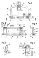
- FIG. 1 is a top view of a mechanism for driving the fabric for a sewing machine provided with this articulation device.
- Figure 2 is an elevational view along line II-II of Figure 1.
- Figure 3 is a sectional view along line III-III of Figure 2.
- Figure 4 is an elevational view along line IV-IV of Figure 2.
- FIG. 5 is a partial view in section on a larger scale along the line V-V of FIG. 2.
- FIG. 6 is an exploded perspective view of FIG. 5.
- the mechanism illustrated by way of example, provided with the articulation device between two levers, object of the invention, is here a mechanism for driving the fabric of a sewing machine. Since this mechanism is not strictly speaking part of the present invention, but only serves to show an example of application, it will not be described in full insofar as this description is not necessary for understanding the invention.
- Figures 1 to 4 illustrate a rod 1 for connecting the mechanism to a frame (not shown) and on which a lever 2 is pivotally mounted.
- This lever comprises two arms 2a, 2b, integral with a connecting element 2c provided with a longitudinal recess 3 open laterally to receive the rod 1.
- the free ends of the arms 2a and 2b are each articulated at the free end of the two arm 5a, 5b of a stirrup-shaped piece 5, the middle arm 5c of which carries a claw 8 intended to drive the fabric to be sewn in successive steps in a determined direction.
- FIG. 2 shows that the ends of the arms 2a and 2b articulated to the stirrup-shaped part 5, terminate in forks whose the branches are designated by 7a, 7b, respectively 6a, 6b, receiving between them the arms 5a, respectively 5b, of the stirrup 5.
- each branch 6a, 6b, 7a, 7b of which only the branches 6a, 6b are illustrated in Figure 6 has a recess 9 formed on its internal face. This recess 9 is parallel to this internal face of the branch 6a, 6b and extends in the longitudinal direction of this branch thus opening at its end to provide a passage for receiving a pivot 10.
- FIG. 1 shows that the ends of the arms 2a and 2b articulated to the stirrup-shaped part 5, terminate in forks whose the branches are designated by 7a, 7b, respectively 6a, 6b, receiving between them the arms 5a, respectively 5b, of the stirrup 5.
- this clearance does not cross the entire thickness of the branches 6a, 6b, in order to reserve axial abutment faces for retaining the pivot 10.
- the bottom of the lateral face 9a of each recess 9 serves as a pivot surface for the pivot 10.
- the end of the arm 5b of the stirrup-shaped part 5 inserted between the arms 6a, 6b of the fork has a lateral recess 11 intended to engage on the pivot 10.
- the part of the end of the arm 5b, opposite the lateral face into which the lateral recess 11 opens, has a semicircular groove 12 concentric with the axis of the pivot 10. This groove 12 is used for hooking one of the ends of a tension spring to coil 13.
- the arms 2a and 2b of the lever 2 have a semi-annular section as seen in particular in Figure 6, thus providing a laterally open channel for the passage of the spring with flange 13, the other end of which is hooked on the rod 1 passing through the longitudinal recess 3 of the connecting element 2c secured to the levers 2a and 2b.
Landscapes
- Engineering & Computer Science (AREA)
- Textile Engineering (AREA)
- General Engineering & Computer Science (AREA)
- Mechanical Engineering (AREA)
- Sewing Machines And Sewing (AREA)
- Pivots And Pivotal Connections (AREA)
- Clamps And Clips (AREA)
- Vehicle Body Suspensions (AREA)
Claims (6)
- Gelenkvorrichtung zwischen zwei Hebeln (2a, 5a; 2b, 5a), bei denen ein Ende eines ersten Hebels (2a, 2b) eine Gabel bildet, die zwischen ihren Schenkein (6a, 6b; 7a, 7b) ein Ende eines zweiten Hebels (5b) aufnimmt,
dadurch gekennzeichnet, daß eine Aussparung (9) an jedem der Schenkel (6a, 6b) in Längsrichtung des Schenkels eingearbeitet ist, die an ihrem Ende ausmündet, um einen seitlichen Gang zum Einführen des Endes einer Schwenkachse (10) zwischen den Schenkein zu bilden, wobei der Boden der Seitenfläche (9a) jeder Aussparung (9) eine Lageroberfläche eines der Enden der Schwenkachse (10) bildet; daß das benachbarte Ende des zweiten Hebels (5a, 5b) eine Aussparung (11) besitzt, die seitlich an einer seiner Flächen mündet, um den Abschnitt der Schwenkachse (10) zu umgreifen, der sich zwischen den Schenkeln (6a, 6b; 7a, 7b) der Gabel erstreckt; und daß elastische Mittel (13) dazu dienen, auf das Ende des zweiten Hebels (5a, 5b) einen gerichteten seitlichen Druck auszuüben, um die Schwenkachse (10) und die Lagerflächen einerseits, den Boden der Aussparung (11) des zweiten Hebels (5a, 5b) und die Schwenkachse (10) andererseits dauernd aneinander in Berührung zu halten. - Gelenkvorrichtung nach Anspruch 1,
dadurch gekennzeichnet, daß die an den Enden der Schenkel (6a, 6b) der Gabel gebildeten Aussparungen (9) auf der Innenfläche jedes der Schenkel parallel zu dieser Fläche ausgebildet sind, um axiale Anschlagoberflächen für die Schwenkachse (10) zu schaffen. - Gelenkvorrichtung nach Anspruch 1,
dadurch gekennzeichnet, daß das Ende des zweiten Hebels (5a, 5b) Mittel (12) aufweist, die zum Einhaken des Endes einer Schraubenzugfeder (13) dienen, deren anderes Ende fest mit dem ersten Hebel (2b) verbunden ist. - Gelenkvorrichtung nach Anspruch 3,
dadurch gekennzeichnet, daß der Abschnitt des Endes des zweiten Hebels (5a, 5b), der der Seitenfläche gegenüberliegt, in die die Aussparung (11) mündet, in seinem mittleren Abschnitt eine Nut (12) aufweist, die konzentrisch zur Achse der Schwenkachse (10) verläuft und zum Einhaken des Endes der Schraubendruckfeder (13) dient. - Gelenkvorrichtung nach Anspruch 3,
dadurch gekennzeichnet, daß das zweite Ende der Zugfeder (13) um eine zweite Schwenkachse (1) gehakt ist, die parallel zur ersten verläuft und seitlich in einer Aussparung (3) gefaßt ist, deren Boden die Lageroberfläche er zweiten Schwenkachse (1) bildet und am anderen Ende des ersten Hebels (2a, 2b) eingearbeitet ist. - Gelenkvorrichtung nach einem der vorhergehenden Ansprüche,
dadurch gekennzeichnet, daß jeder der genannten Hebel mit seinen Lageroberflächen direkt aus der Formarbeit hervorgegangen ist.
Applications Claiming Priority (2)
| Application Number | Priority Date | Filing Date | Title |
|---|---|---|---|
| CH3779/90 | 1990-11-29 | ||
| CH3779/90A CH684416A5 (fr) | 1990-11-29 | 1990-11-29 | Dispositif d'articulation entre deux leviers. |
Publications (2)
| Publication Number | Publication Date |
|---|---|
| EP0488957A1 EP0488957A1 (de) | 1992-06-03 |
| EP0488957B1 true EP0488957B1 (de) | 1994-08-31 |
Family
ID=4263308
Family Applications (1)
| Application Number | Title | Priority Date | Filing Date |
|---|---|---|---|
| EP91810919A Expired - Lifetime EP0488957B1 (de) | 1990-11-29 | 1991-11-26 | Gelenkvorrichtung zwischen zwei Hebeln |
Country Status (9)
| Country | Link |
|---|---|
| US (1) | US5143470A (de) |
| EP (1) | EP0488957B1 (de) |
| JP (1) | JPH04266609A (de) |
| CN (1) | CN1025926C (de) |
| BR (1) | BR9105187A (de) |
| CH (1) | CH684416A5 (de) |
| DE (1) | DE69103736T2 (de) |
| ES (1) | ES2061219T3 (de) |
| RU (1) | RU2040712C1 (de) |
Families Citing this family (6)
| Publication number | Priority date | Publication date | Assignee | Title |
|---|---|---|---|---|
| DE4227291A1 (de) * | 1992-08-18 | 1994-02-24 | Wabco Westinghouse Fahrzeug | Gabelgelenk |
| BR9304034A (pt) * | 1993-10-19 | 1995-06-20 | Brasil Compressores Sa | Biela bi-partida para compressor hermético alternativo |
| CN100582506C (zh) * | 2006-04-28 | 2010-01-20 | 鸿富锦精密工业(深圳)有限公司 | 转动机构 |
| CN102003454B (zh) * | 2010-11-03 | 2013-01-02 | 倪湘凝 | 火炬台顶升机构用的铰接装置 |
| RU2507326C2 (ru) * | 2012-05-03 | 2014-02-20 | Федеральное государственное бюджетное образовательное учреждение высшего профессионального образования "Ивановская государственная текстильная академия" (ИГТА) | Механизм транспортирования ткани швейной машины |
| CN108118459A (zh) * | 2016-11-29 | 2018-06-05 | 深圳市德业智能股份有限公司 | 一种物料定位装置以及一种缝纫设备 |
Family Cites Families (15)
| Publication number | Priority date | Publication date | Assignee | Title |
|---|---|---|---|---|
| DE177846C (de) * | ||||
| US458228A (en) * | 1891-08-25 | Sachusetts | ||
| DE7411070U (de) * | 1974-12-12 | Blaupunkt Werke Gmbh | Kunststoffgelenk | |
| US915524A (en) * | 1908-11-20 | 1909-03-16 | John G Wise | Switch-rod connection. |
| US2372120A (en) * | 1943-09-30 | 1945-03-20 | Lonnie M Roberson | Rotatable truck standard |
| US2834277A (en) * | 1953-08-13 | 1958-05-13 | Allis Chalmers Mfg Co | Quick hitch system |
| US3036536A (en) * | 1959-02-12 | 1962-05-29 | Singer Mfg Co | Presser lifter mechanism for sewing machines |
| DE1425957A1 (de) * | 1964-04-14 | 1969-03-20 | Willy Herold | Selbsthemmendes Gelenk |
| IT1073022B (it) * | 1976-10-13 | 1985-04-13 | Rockwell Rimoldi Spa | Comando per un dispositivo di regolazione del trasporto differenziale di una macchina per cucire |
| US4170804A (en) * | 1978-05-15 | 1979-10-16 | Vanauto Accessories Proprietary Limited | Wiper arm and mounting head |
| US4541354A (en) * | 1984-03-30 | 1985-09-17 | Janome Sewing Machine Industry Co., Ltd. | Feed reference point balancing device of sewing machine |
| DE3500336A1 (de) * | 1985-01-08 | 1986-07-10 | Klöckner-Humboldt-Deutz AG, 5000 Köln | Spielausgleich in den gelenken einer koppelstange |
| IT8522117V0 (it) * | 1985-06-07 | 1985-06-07 | Eurodomestici Ind Riunite | Biellismo per piccole macchine monocilindriche alternative, particolarmente per compressori per frigoriferi. |
| DE3628115A1 (de) * | 1986-08-19 | 1988-02-25 | Heinz Klein | Scharnier, insb. fuer moebel |
| CH677804A5 (de) * | 1988-11-30 | 1991-06-28 | Mefina Sa |
-
1990
- 1990-11-29 CH CH3779/90A patent/CH684416A5/fr not_active IP Right Cessation
-
1991
- 1991-11-26 EP EP91810919A patent/EP0488957B1/de not_active Expired - Lifetime
- 1991-11-26 ES ES91810919T patent/ES2061219T3/es not_active Expired - Lifetime
- 1991-11-26 DE DE69103736T patent/DE69103736T2/de not_active Expired - Fee Related
- 1991-11-26 CN CN91111210A patent/CN1025926C/zh not_active Expired - Fee Related
- 1991-11-28 JP JP3314644A patent/JPH04266609A/ja active Pending
- 1991-11-28 BR BR919105187A patent/BR9105187A/pt not_active Application Discontinuation
- 1991-11-28 RU SU915010220A patent/RU2040712C1/ru active
- 1991-11-29 US US07/798,926 patent/US5143470A/en not_active Expired - Fee Related
Also Published As
| Publication number | Publication date |
|---|---|
| DE69103736D1 (de) | 1994-10-06 |
| CN1062022A (zh) | 1992-06-17 |
| CH684416A5 (fr) | 1994-09-15 |
| DE69103736T2 (de) | 1995-03-02 |
| CN1025926C (zh) | 1994-09-14 |
| EP0488957A1 (de) | 1992-06-03 |
| JPH04266609A (ja) | 1992-09-22 |
| BR9105187A (pt) | 1992-07-21 |
| RU2040712C1 (ru) | 1995-07-25 |
| US5143470A (en) | 1992-09-01 |
| ES2061219T3 (es) | 1994-12-01 |
Similar Documents
| Publication | Publication Date | Title |
|---|---|---|
| FR2621665A1 (fr) | Dispositif d'entrainement d'essuie-glace de vehicules automobiles dont le guide dispose sur la premiere partie de la manivelle est sous forme d'une cavite en forme de coulisse | |
| EP0488957B1 (de) | Gelenkvorrichtung zwischen zwei Hebeln | |
| FR2476994A1 (fr) | Appareil electrique a main, en particulier brosse a dents electrique | |
| WO2009056760A1 (fr) | Articulation a rotule a debattement limite | |
| FR2485124A1 (fr) | Mecanisme a manivelle pour petites machines alternatives monocylindres, notamment compresseurs pour refrigerateurs | |
| EP0488857B1 (de) | Interne Steuervorrichtung für Schaltgetriebe | |
| FR2563176A1 (fr) | Dispositif de montage notamment de l'articulation du bras tendeur guide-chaine des changements de vitesse pour bicyclettes et vehicules similaires | |
| FR2811050A1 (fr) | Dipositif d'actionnement pour une boite de vitesses a pignons dentes | |
| EP0163583B1 (de) | Montagevorrichtung, insbesondere vom Gelenk des Spannarmes der Kettenführung der Gangschaltung für Fahrräder oder ähnliche Fahrzeuge | |
| EP0214074B1 (de) | Kraftübersetzer für die Fachbildungsvorrichtung einer Webmaschine | |
| FR2515560A1 (fr) | Outil a rochet | |
| FR2465810A1 (fr) | Mecanisme de liaison amovible du dispositif de formation de la foule d'une machine a tisser | |
| EP1694470B1 (de) | Vorrichtung zur montage des gehäuses und des körpers eines hydraulischen gesteinsbrechers | |
| FR2560327A1 (fr) | Dispositif anti-battement pour une biellette | |
| FR2924476A3 (fr) | Dispositif de liaison articule pour elements tubulaires rigides et dispositif de commande externe de boite de vitesses | |
| EP0794337A1 (de) | Bajonettschnellkupplung | |
| FR2842485A1 (fr) | Piece de liaison d'un bras d'essuie-glace et d'un balai d'essuie-glace sans articulation | |
| FR2499658A1 (fr) | Transmission d'entrainement pour un outil a oscillation planaire ainsi que son utilisation | |
| CH707555B1 (fr) | Mécanisme de transmission de mouvements axiaux et rotatifs entre deux axes décalés et pièce d'horlogerie comportant ce mécanisme. | |
| FR2488663A1 (fr) | Dispositif de retenue d'un corps entre deux pieces paralleles l'une a l'autre | |
| EP4108517A1 (de) | Einstellvorrichtung für einen kraftfahrzeugsitz | |
| FR2761426A1 (fr) | Palier de guidage pour un axe de fourchette de boite de vitesses | |
| FR2536706A1 (fr) | Dispositif de commande mecanique de boite de vitesses | |
| FR2529285A1 (fr) | Engrenage helicoidal | |
| FR2636589A1 (fr) | Dispositif de changement de vitesse pour cycle |
Legal Events
| Date | Code | Title | Description |
|---|---|---|---|
| PUAI | Public reference made under article 153(3) epc to a published international application that has entered the european phase |
Free format text: ORIGINAL CODE: 0009012 |
|
| AK | Designated contracting states |
Kind code of ref document: A1 Designated state(s): CH DE ES FR GB IT LI SE |
|
| 17P | Request for examination filed |
Effective date: 19920702 |
|
| 17Q | First examination report despatched |
Effective date: 19931102 |
|
| GRAA | (expected) grant |
Free format text: ORIGINAL CODE: 0009210 |
|
| AK | Designated contracting states |
Kind code of ref document: B1 Designated state(s): CH DE ES FR GB IT LI SE |
|
| PGFP | Annual fee paid to national office [announced via postgrant information from national office to epo] |
Ref country code: FR Payment date: 19940929 Year of fee payment: 4 |
|
| REF | Corresponds to: |
Ref document number: 69103736 Country of ref document: DE Date of ref document: 19941006 |
|
| PGFP | Annual fee paid to national office [announced via postgrant information from national office to epo] |
Ref country code: ES Payment date: 19941010 Year of fee payment: 4 |
|
| PGFP | Annual fee paid to national office [announced via postgrant information from national office to epo] |
Ref country code: DE Payment date: 19941018 Year of fee payment: 4 |
|
| ITF | It: translation for a ep patent filed | ||
| PGFP | Annual fee paid to national office [announced via postgrant information from national office to epo] |
Ref country code: SE Payment date: 19941122 Year of fee payment: 4 |
|
| PGFP | Annual fee paid to national office [announced via postgrant information from national office to epo] |
Ref country code: CH Payment date: 19941129 Year of fee payment: 4 |
|
| REG | Reference to a national code |
Ref country code: ES Ref legal event code: FG2A Ref document number: 2061219 Country of ref document: ES Kind code of ref document: T3 |
|
| GBT | Gb: translation of ep patent filed (gb section 77(6)(a)/1977) |
Effective date: 19941124 |
|
| EAL | Se: european patent in force in sweden |
Ref document number: 91810919.0 |
|
| PLBE | No opposition filed within time limit |
Free format text: ORIGINAL CODE: 0009261 |
|
| STAA | Information on the status of an ep patent application or granted ep patent |
Free format text: STATUS: NO OPPOSITION FILED WITHIN TIME LIMIT |
|
| 26N | No opposition filed | ||
| PG25 | Lapsed in a contracting state [announced via postgrant information from national office to epo] |
Ref country code: GB Effective date: 19951126 |
|
| PG25 | Lapsed in a contracting state [announced via postgrant information from national office to epo] |
Ref country code: SE Effective date: 19951127 Ref country code: ES Free format text: LAPSE BECAUSE OF THE APPLICANT RENOUNCES Effective date: 19951127 |
|
| PG25 | Lapsed in a contracting state [announced via postgrant information from national office to epo] |
Ref country code: LI Effective date: 19951130 Ref country code: CH Effective date: 19951130 |
|
| REG | Reference to a national code |
Ref country code: CH Ref legal event code: PL |
|
| GBPC | Gb: european patent ceased through non-payment of renewal fee |
Effective date: 19951126 |
|
| PG25 | Lapsed in a contracting state [announced via postgrant information from national office to epo] |
Ref country code: FR Effective date: 19960731 |
|
| PG25 | Lapsed in a contracting state [announced via postgrant information from national office to epo] |
Ref country code: DE Effective date: 19960801 |
|
| EUG | Se: european patent has lapsed |
Ref document number: 91810919.0 |
|
| REG | Reference to a national code |
Ref country code: FR Ref legal event code: ST |
|
| REG | Reference to a national code |
Ref country code: ES Ref legal event code: FD2A Effective date: 20010402 |
|
| PG25 | Lapsed in a contracting state [announced via postgrant information from national office to epo] |
Ref country code: IT Free format text: LAPSE BECAUSE OF NON-PAYMENT OF DUE FEES;WARNING: LAPSES OF ITALIAN PATENTS WITH EFFECTIVE DATE BEFORE 2007 MAY HAVE OCCURRED AT ANY TIME BEFORE 2007. THE CORRECT EFFECTIVE DATE MAY BE DIFFERENT FROM THE ONE RECORDED. Effective date: 20051126 |