EP0489044B1 - Building method - Google Patents
Building method Download PDFInfo
- Publication number
- EP0489044B1 EP0489044B1 EP90912163A EP90912163A EP0489044B1 EP 0489044 B1 EP0489044 B1 EP 0489044B1 EP 90912163 A EP90912163 A EP 90912163A EP 90912163 A EP90912163 A EP 90912163A EP 0489044 B1 EP0489044 B1 EP 0489044B1
- Authority
- EP
- European Patent Office
- Prior art keywords
- elements
- building method
- floor
- conduits
- concrete
- Prior art date
- Legal status (The legal status is an assumption and is not a legal conclusion. Google has not performed a legal analysis and makes no representation as to the accuracy of the status listed.)
- Expired - Lifetime
Links
- 238000000034 method Methods 0.000 title claims abstract description 20
- 239000004567 concrete Substances 0.000 claims abstract description 24
- 125000006850 spacer group Chemical group 0.000 claims abstract description 19
- 229910000831 Steel Inorganic materials 0.000 claims description 10
- 239000010959 steel Substances 0.000 claims description 10
- 230000002787 reinforcement Effects 0.000 claims description 4
- 239000011150 reinforced concrete Substances 0.000 claims description 3
- 230000005611 electricity Effects 0.000 abstract description 3
- 238000009423 ventilation Methods 0.000 abstract description 3
- 239000011796 hollow space material Substances 0.000 description 2
- 230000009970 fire resistant effect Effects 0.000 description 1
- 238000010438 heat treatment Methods 0.000 description 1
- 238000009434 installation Methods 0.000 description 1
- 235000000396 iron Nutrition 0.000 description 1
- 239000000463 material Substances 0.000 description 1
- 239000002184 metal Substances 0.000 description 1
Images



Classifications
-
- E—FIXED CONSTRUCTIONS
- E04—BUILDING
- E04B—GENERAL BUILDING CONSTRUCTIONS; WALLS, e.g. PARTITIONS; ROOFS; FLOORS; CEILINGS; INSULATION OR OTHER PROTECTION OF BUILDINGS
- E04B5/00—Floors; Floor construction with regard to insulation; Connections specially adapted therefor
- E04B5/48—Special adaptations of floors for incorporating ducts, e.g. for heating or ventilating
-
- E—FIXED CONSTRUCTIONS
- E04—BUILDING
- E04B—GENERAL BUILDING CONSTRUCTIONS; WALLS, e.g. PARTITIONS; ROOFS; FLOORS; CEILINGS; INSULATION OR OTHER PROTECTION OF BUILDINGS
- E04B5/00—Floors; Floor construction with regard to insulation; Connections specially adapted therefor
- E04B5/43—Floor structures of extraordinary design; Features relating to the elastic stability; Floor structures specially designed for resting on columns only, e.g. mushroom floors
Definitions
- the invention relates to a building method comprising placing columns in a rectangular grid arrangement, fixing horizontal supporting elements to said columns and supporting concrete floors by said supporting elements, said supporting elements forming a system of girders, each provided with a number of adjacent, spaced feed-through conduits.
- the floors consist of U- or L-shaped elements which also function as installation ducts.
- this method is complicated and expensive.
- the object of the invention is to avoid the above mentioned disadvantages of the known methods and to this end the building method mentioned in the preamble is characterised in that the above mentioned supporting elements provide floor elements made of prefabricated hollow elements, each element having a bottom sheet, a top sheet and spacers arranged in a grid between said sheets, the bottom sheet of each floor element having laterally projecting parts at two opposite sides; raising said floor elements until said projecting parts lie against said supporting elements; and connecting said projecting parts to the underside of said supporting elements.
- FR-A-2142887 discloses a floor made of prefabricated hollow elements, each having a bottom sheet, a top sheet and spacers arranged in a grid shape placed between them. From this specification it is not known to connect a floor element to a supporting element by raising the floor element untill a projecting part thereof lie against a supporting element and to connect said projecting part to the underside of the supporting element.
- the feed-through conduits are used for feeding through lines and cables.
- the floor elements are rectangular and are fixed solely by their short sides to the girders.
- the girders are steel section beams, they will have to (and/or can) be protected against fire.
- the rows of spacers adjacent to the projecting parts project between the feed-through conduits of the girders, while concrete is poured in the spaces bounded by the external surface of the feed-through conduits and the end faces of the spacers projecting between the feed-through conduits.
- the girders are preferably steel I beams.
- the steel beams can also be channel beams, in which case a reinforced concrete is placed in the channel beam.
- the beams can comprise two tilted channel beams held apart by transverse conduits, and the space between said beams is filled with concrete.
- the top sheet is provided with apertures which are placed in a grid arrangement and can be covered with tile-type sheets abutting each other.
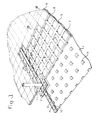
- Figure 1 shows a perspective view of a part of a structure built according to the invention, for the sake of clarity parts of some floor elements being shown partially cut away.
- Figure 2 is a section along the line II-II in Figure 1.
- Figure 3 is a section along the line III-III in Fig. 1.
- Figure 4 is a section along the line IV-IV in Figure 1.
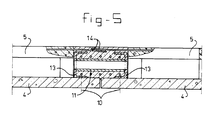
- Figure 5 shows a section comparable to that of Figure 4 of an alternative girder design.
- Figure 6 shows a perspective view of a structure in which the preferred method according to the invention is used.
- Figure 7 shows a section along the line VII-VII in Figure 6.
- the structure shown comprises a number of columns 1, preferably of steel, placed in a rectangular grid arrangement. At each column a number of crowns 2 are placed above one another. The vertical distance between the crowns corresponds to the height of storey. Since such a system is known per se, only one column with one crown is shown in Figure 1.
- the invention is concerned with the way in which prefabricated floor elements are supported relative to the columns 1.
- the prefabricated floor elements are of dimensions of, for example, 720 x 240 cm.
- girders in the form of steel channel beams 3 are fixed between the crowns 2 situated at the same level. These beams run parallel to each other, and their lengthwise direction coincides with the direction of the transverse edges of the prefabricated concrete floor elements which are fixed to the channel beams and will be described in greater detail below.
- Each floor element comprises a bottom sheet 4, a top sheet 5, and fitted between said sheets spacers 6 in the form of lobes which are moulded onto the bottom face of the-top sheet and are in a grid arrangement.
- the bottom sheet 4 is anchored to the lobes 6 through reinforcement ties 7 being concreted into the lobes and projecting at the bottom side, and being forced into the concrete of the bottom sheet before this concrete is set.
- Figure 1 shows the bottom sheet 4 of a first floor element without top sheet and the bottom sheet 4 with top sheet 5 of the second floor element.
- the top sheet is provided with apertures 8 placed in a grid arrangement and covered with tile-shaped sheets 9.
- top sheets 5 at the transverse edges of the floor elements abut one leg of a channel beam 3, while the bottom sheets 4 at their transverse edges project under the body of a channel beam 4 at 4a up to the transverse edge of the bottom sheet 4 of another floor element.
- each crown 2 At the position of each crown 2, a recess is provided in the corners of a floor element, into which recess a part of the crown fits.
- the channel beams 3 are provided with transverse feed-through conduits 11 which open out into apertures 12 in the legs of the beams 3, and which serve to carry lines or cables from a hollow space of one floor element through the channel beams 3 to the hollow space of another floor element.
- Reinforced concrete is poured into the channel beams, so that the channel beams serve as permanent falsework. If the channel beams are destroyed by fire, the concrete remains in place.
- FIG. 5 The embodiment shown in Figure 5 is intended for higher floors. Instead of a channel beam 3, use is made of two channel beams 13 which are tilted through 90°, and between which transverse conduits 11 are welded, which conduits open out into openings in the body of the channel beams 13. Lock-woven mesh is placed in the space between the channel beams 13 and concrete is poured. The top sheets 5 are provided at their transverse edges with projecting reinforcement irons 14, the projecting part of which is embedded in the concrete between the channel beams 13.
- the girders are in the form of I beams 20 which are fixed to the columns 1 without crowns between them.
- the hollow floor elements comprising a bottom sheet 4, a top sheet 5, and spacers 6 placed in a grid arrangement between said sheets are fixed at their transverse end edges to the I beams 20 through the projecting parts 4a of the bottom sheet 4 being engaged with the bottom flange of the I beams and fixed by bolts 10 when the floor elements are raised.
- the rows of spacers 6a adjacent to the projecting bottom sheet parts 4a are made elongated and project between the feed-through conduits 11. Concrete is poured into the spaces 21 bounded by the outer surface of the feed-through conduits and the end faces 6b of the spacers 6, so that the I beams 20 and the conduits 11 are completely embedded in concrete. This greatly improves fire safety.
- the seams between the bottom sheets 4 of the floor elements are sealed with a sealer or shaped metal strip.
- All kinds of facilities including those in the field of heating, ventilation, electricity, telephone, computers, can be accommodated in the hollow floor elements, so that a separate space for these underneath the floor is not necessary.
- the storey height of a building can be limited as a result of this.
- After the fitting of a floor it is possible to start immediately on the fitting of the next floor, which means that building can be speeded up considerably compared with a building system in which the floors are poured on the spot. It is possible to work immediately on each fitted floor, since there is no need to wait for setting and there are no supports on it for the next floor. If there are steel columns, they are enclosed with fire-resistant material.
Landscapes
- Engineering & Computer Science (AREA)
- Architecture (AREA)
- Physics & Mathematics (AREA)
- Electromagnetism (AREA)
- Civil Engineering (AREA)
- Structural Engineering (AREA)
- On-Site Construction Work That Accompanies The Preparation And Application Of Concrete (AREA)
- Table Devices Or Equipment (AREA)
- Conveying And Assembling Of Building Elements In Situ (AREA)
- Air Transport Of Granular Materials (AREA)
- Floor Finish (AREA)
- Installation Of Indoor Wiring (AREA)
- Buildings Adapted To Withstand Abnormal External Influences (AREA)
- Chemical And Physical Treatments For Wood And The Like (AREA)
Applications Claiming Priority (2)
| Application Number | Priority Date | Filing Date | Title |
|---|---|---|---|
| NL8902130 | 1989-08-23 | ||
| NL8902130A NL8902130A (nl) | 1989-08-23 | 1989-08-23 | Bouwwerk en voor dat bouwwerk geschikte geprefabriceerde vloerelementen. |
Publications (2)
| Publication Number | Publication Date |
|---|---|
| EP0489044A1 EP0489044A1 (en) | 1992-06-10 |
| EP0489044B1 true EP0489044B1 (en) | 1993-03-03 |
Family
ID=19855207
Family Applications (1)
| Application Number | Title | Priority Date | Filing Date |
|---|---|---|---|
| EP90912163A Expired - Lifetime EP0489044B1 (en) | 1989-08-23 | 1990-08-22 | Building method |
Country Status (8)
| Country | Link |
|---|---|
| EP (1) | EP0489044B1 (da) |
| AT (1) | ATE86335T1 (da) |
| AU (1) | AU6170890A (da) |
| DE (1) | DE69001020T2 (da) |
| DK (1) | DK0489044T3 (da) |
| ES (1) | ES2040602T3 (da) |
| NL (1) | NL8902130A (da) |
| WO (1) | WO1991002859A1 (da) |
Families Citing this family (2)
| Publication number | Priority date | Publication date | Assignee | Title |
|---|---|---|---|---|
| EP3401460A1 (de) * | 2017-05-10 | 2018-11-14 | Holger Rupprecht | Querlastverteiltes holz-beton-verbund-system |
| FR3076845B1 (fr) * | 2018-01-16 | 2020-02-07 | Kp1 | Predalle a blocs d'armatures |
Family Cites Families (6)
| Publication number | Priority date | Publication date | Assignee | Title |
|---|---|---|---|---|
| DE1250998B (da) * | 1967-09-28 | |||
| FR2142887B1 (da) * | 1971-06-25 | 1975-07-11 | Ortmann Frank | |
| DE2324224A1 (de) * | 1973-05-14 | 1974-12-05 | Wilhelm Johannes Di Silberkuhl | Hochhaus |
| US4211045A (en) * | 1977-01-20 | 1980-07-08 | Kajima Kensetsu Kabushiki Kaisha | Building structure |
| ATE20106T1 (de) * | 1982-08-17 | 1986-06-15 | Ruffer Dittmar | Aufgeloeste selbsttragende bauplatte - erzeugnis - verfahren - vorrichtung - verwendung. |
| DE3309820C2 (de) * | 1983-03-18 | 1986-07-31 | Ainedter, Dieter, Dipl.-Ing., Salzburg | Deckenplatte und Verfahren zu ihrer Herstellung |
-
1989
- 1989-08-23 NL NL8902130A patent/NL8902130A/nl not_active Application Discontinuation
-
1990
- 1990-08-22 DK DK90912163.4T patent/DK0489044T3/da active
- 1990-08-22 EP EP90912163A patent/EP0489044B1/en not_active Expired - Lifetime
- 1990-08-22 AT AT90912163T patent/ATE86335T1/de not_active IP Right Cessation
- 1990-08-22 DE DE9090912163T patent/DE69001020T2/de not_active Expired - Fee Related
- 1990-08-22 WO PCT/NL1990/000122 patent/WO1991002859A1/en not_active Ceased
- 1990-08-22 AU AU61708/90A patent/AU6170890A/en not_active Abandoned
- 1990-08-22 ES ES199090912163T patent/ES2040602T3/es not_active Expired - Lifetime
Also Published As
| Publication number | Publication date |
|---|---|
| DE69001020T2 (de) | 1993-07-01 |
| ATE86335T1 (de) | 1993-03-15 |
| DK0489044T3 (da) | 1993-06-21 |
| WO1991002859A1 (en) | 1991-03-07 |
| AU6170890A (en) | 1991-04-03 |
| ES2040602T3 (es) | 1993-10-16 |
| EP0489044A1 (en) | 1992-06-10 |
| DE69001020D1 (de) | 1993-04-08 |
| NL8902130A (nl) | 1991-03-18 |
Similar Documents
| Publication | Publication Date | Title |
|---|---|---|
| US4328651A (en) | Precast concrete constructions | |
| US5987827A (en) | Concrete building construction and method | |
| KR100927344B1 (ko) | 흙막이벽과 바닥구조체의 연결 시공을 위한 연결구조체와이를 이용한 지하구조물의 바닥구조체 시공방법 | |
| JPH11152761A (ja) | 地下構造物およびその構築工法 | |
| EP0489044B1 (en) | Building method | |
| CA1167272A (en) | Pre-cast building unit, building and method utilizing same, and casting form therefor | |
| JPS627344B2 (da) | ||
| US2379636A (en) | Method of making reinforced concrete buildings | |
| JP3240438B2 (ja) | 免震建物および既存建物の免震化工法 | |
| KR0171873B1 (ko) | 선시공되는 코아를 이용한 고층건축물의 시공방법 | |
| RU97112678A (ru) | Каркас здания и способ его возведения | |
| US3199259A (en) | Anchoring structure for building slabs | |
| GB2062079A (en) | Precast Wall Unit for Silage Pit or Tank | |
| FI94451B (fi) | Betonilaattarakenteiden yhteydessä käytettäväksi tarkoitettu betonilla täytettävä liittopalkki | |
| EP0483089A2 (en) | A beam for floor structures | |
| CA1296916C (en) | Structural panel and method of forming same | |
| EP0382694B1 (en) | A method of connecting horizontal beams to steel colums of a building and a building erected according to said method | |
| KR200149664Y1 (ko) | 스테인레스재를 이용한 실내수영장의 바닥판 지지장치 | |
| SU1735523A1 (ru) | Вис чее скатное и внутрискатное покрытие зданий и сооружений | |
| JPH0791876B2 (ja) | 放射線遮蔽スラブとその施工法 | |
| JP2780055B2 (ja) | 鉄筋コンクリート造建築物の構築工法 | |
| JP2536250Y2 (ja) | 鋼製基礎梁 | |
| JPH082260Y2 (ja) | 断熱床構造材 | |
| KR910006123Y1 (ko) | 슬래브구축용 철근형틀 | |
| JPS6315412B2 (da) |
Legal Events
| Date | Code | Title | Description |
|---|---|---|---|
| PUAI | Public reference made under article 153(3) epc to a published international application that has entered the european phase |
Free format text: ORIGINAL CODE: 0009012 |
|
| 17P | Request for examination filed |
Effective date: 19920220 |
|
| AK | Designated contracting states |
Kind code of ref document: A1 Designated state(s): AT BE CH DE DK ES FR GB IT LI LU NL SE |
|
| 17Q | First examination report despatched |
Effective date: 19920806 |
|
| GRAA | (expected) grant |
Free format text: ORIGINAL CODE: 0009210 |
|
| AK | Designated contracting states |
Kind code of ref document: B1 Designated state(s): AT BE CH DE DK ES FR GB IT LI LU NL SE |
|
| REF | Corresponds to: |
Ref document number: 86335 Country of ref document: AT Date of ref document: 19930315 Kind code of ref document: T |
|
| REF | Corresponds to: |
Ref document number: 69001020 Country of ref document: DE Date of ref document: 19930408 |
|
| ET | Fr: translation filed | ||
| ITF | It: translation for a ep patent filed | ||
| REG | Reference to a national code |
Ref country code: DK Ref legal event code: T3 |
|
| REG | Reference to a national code |
Ref country code: ES Ref legal event code: FG2A Ref document number: 2040602 Country of ref document: ES Kind code of ref document: T3 |
|
| PLBE | No opposition filed within time limit |
Free format text: ORIGINAL CODE: 0009261 |
|
| STAA | Information on the status of an ep patent application or granted ep patent |
Free format text: STATUS: NO OPPOSITION FILED WITHIN TIME LIMIT |
|
| 26N | No opposition filed | ||
| EPTA | Lu: last paid annual fee | ||
| EAL | Se: european patent in force in sweden |
Ref document number: 90912163.4 |
|
| PGFP | Annual fee paid to national office [announced via postgrant information from national office to epo] |
Ref country code: ES Payment date: 19970212 Year of fee payment: 7 |
|
| PGFP | Annual fee paid to national office [announced via postgrant information from national office to epo] |
Ref country code: NL Payment date: 19970213 Year of fee payment: 7 Ref country code: GB Payment date: 19970213 Year of fee payment: 7 |
|
| PGFP | Annual fee paid to national office [announced via postgrant information from national office to epo] |
Ref country code: SE Payment date: 19970214 Year of fee payment: 7 Ref country code: FR Payment date: 19970214 Year of fee payment: 7 |
|
| PGFP | Annual fee paid to national office [announced via postgrant information from national office to epo] |
Ref country code: CH Payment date: 19970217 Year of fee payment: 7 |
|
| PGFP | Annual fee paid to national office [announced via postgrant information from national office to epo] |
Ref country code: DK Payment date: 19970221 Year of fee payment: 7 Ref country code: AT Payment date: 19970221 Year of fee payment: 7 |
|
| PGFP | Annual fee paid to national office [announced via postgrant information from national office to epo] |
Ref country code: DE Payment date: 19970225 Year of fee payment: 7 |
|
| PGFP | Annual fee paid to national office [announced via postgrant information from national office to epo] |
Ref country code: LU Payment date: 19970318 Year of fee payment: 7 |
|
| PGFP | Annual fee paid to national office [announced via postgrant information from national office to epo] |
Ref country code: BE Payment date: 19970407 Year of fee payment: 7 |
|
| PG25 | Lapsed in a contracting state [announced via postgrant information from national office to epo] |
Ref country code: LU Free format text: LAPSE BECAUSE OF NON-PAYMENT OF DUE FEES Effective date: 19970822 Ref country code: GB Free format text: LAPSE BECAUSE OF NON-PAYMENT OF DUE FEES Effective date: 19970822 Ref country code: DK Free format text: LAPSE BECAUSE OF NON-PAYMENT OF DUE FEES Effective date: 19970822 Ref country code: AT Free format text: LAPSE BECAUSE OF NON-PAYMENT OF DUE FEES Effective date: 19970822 |
|
| REG | Reference to a national code |
Ref country code: DK Ref legal event code: EBP |
|
| PG25 | Lapsed in a contracting state [announced via postgrant information from national office to epo] |
Ref country code: SE Free format text: LAPSE BECAUSE OF NON-PAYMENT OF DUE FEES Effective date: 19970823 Ref country code: ES Free format text: LAPSE BECAUSE OF THE APPLICANT RENOUNCES Effective date: 19970823 |
|
| PG25 | Lapsed in a contracting state [announced via postgrant information from national office to epo] |
Ref country code: LI Free format text: LAPSE BECAUSE OF NON-PAYMENT OF DUE FEES Effective date: 19970831 Ref country code: CH Free format text: LAPSE BECAUSE OF NON-PAYMENT OF DUE FEES Effective date: 19970831 Ref country code: BE Free format text: LAPSE BECAUSE OF NON-PAYMENT OF DUE FEES Effective date: 19970831 |
|
| BERE | Be: lapsed |
Owner name: ROETERDINK ANTON JAN Effective date: 19970831 |
|
| PG25 | Lapsed in a contracting state [announced via postgrant information from national office to epo] |
Ref country code: NL Free format text: LAPSE BECAUSE OF NON-PAYMENT OF DUE FEES Effective date: 19980301 |
|
| GBPC | Gb: european patent ceased through non-payment of renewal fee |
Effective date: 19970822 |
|
| REG | Reference to a national code |
Ref country code: CH Ref legal event code: PL |
|
| PG25 | Lapsed in a contracting state [announced via postgrant information from national office to epo] |
Ref country code: FR Free format text: LAPSE BECAUSE OF NON-PAYMENT OF DUE FEES Effective date: 19980430 |
|
| PG25 | Lapsed in a contracting state [announced via postgrant information from national office to epo] |
Ref country code: DE Free format text: LAPSE BECAUSE OF NON-PAYMENT OF DUE FEES Effective date: 19980501 |
|
| EUG | Se: european patent has lapsed |
Ref document number: 90912163.4 |
|
| NLV4 | Nl: lapsed or anulled due to non-payment of the annual fee |
Effective date: 19980301 |
|
| REG | Reference to a national code |
Ref country code: FR Ref legal event code: ST |
|
| REG | Reference to a national code |
Ref country code: ES Ref legal event code: FD2A Effective date: 20001009 |
|
| PG25 | Lapsed in a contracting state [announced via postgrant information from national office to epo] |
Ref country code: IT Free format text: LAPSE BECAUSE OF NON-PAYMENT OF DUE FEES Effective date: 20050822 |