EP0489283A2 - Tube de contrôle avant, à plein calibre, pour une cartouche du type télescopique - Google Patents
Tube de contrôle avant, à plein calibre, pour une cartouche du type télescopique Download PDFInfo
- Publication number
- EP0489283A2 EP0489283A2 EP91119332A EP91119332A EP0489283A2 EP 0489283 A2 EP0489283 A2 EP 0489283A2 EP 91119332 A EP91119332 A EP 91119332A EP 91119332 A EP91119332 A EP 91119332A EP 0489283 A2 EP0489283 A2 EP 0489283A2
- Authority
- EP
- European Patent Office
- Prior art keywords
- control tube
- propellant
- casing
- sabot
- bourrelet
- Prior art date
- Legal status (The legal status is an assumption and is not a legal conclusion. Google has not performed a legal analysis and makes no representation as to the accuracy of the status listed.)
- Withdrawn
Links
Images

Classifications
-
- F—MECHANICAL ENGINEERING; LIGHTING; HEATING; WEAPONS; BLASTING
- F42—AMMUNITION; BLASTING
- F42B—EXPLOSIVE CHARGES, e.g. FOR BLASTING, FIREWORKS, AMMUNITION
- F42B5/00—Cartridge ammunition, e.g. separately-loaded propellant charges
- F42B5/02—Cartridges, i.e. cases with charge and missile
- F42B5/045—Cartridges, i.e. cases with charge and missile of telescopic type
Definitions
- This invention is in the field of cased telescoped ammunition rounds, and more particularly relates to improvements to cased telescoped ammunition rounds with a full caliber control tube in which the projectiles are fin stabilized subcaliber penetrators, with the penetrator of each round being provided with a sabot which separates from the projectile as the projectile and sabot exit the barrel of the gun from which fired.
- cased telescoped ammunition in which the projectile is completely enclosed, or telescoped, within the cartridge case, reduces the volume and weight of gun systems firing cased telescoped ammunition.
- the cylindrical shape of cased telescoped cartridges allows for a simpler more reliable and more compact gun system with a higher rate of fire compared with equivalent gun systems using conventionally shaped rounds.
- the present invention provides an improved cased telescoped ammunition round for a fin stabilized penetrator projectile.
- the cylindrical casing has a rear seal closing the rear end of the casing and a front seal secured to the front end of the casing.
- a tapered full caliber control tube is secured to the front seal of the casing.
- the thickness of the side walls of the control tube increases, or the side walls are tapered, from the rear end to the forward end.
- a sabot which has a forward bourrelet and a rearward bourrelet is mounted around a fin stabilized penetrator.
- a centering band is located in a centering groove of the forward bourrelet, and an obturator band is positioned in an obturator groove of the rearward bourrelet.
- a retaining groove is also formed in the rearward bourrelet aft of the obturator groove.
- the sabot and penetrator are positioned within the control tube.
- a retaining groove near the rear, or free end, of the control tube cooperates by means of a split ring with the retaining groove of the rearward bourrelet to prevent movement of the penetrator and sabot relative to the control tube and casing during normal handling of a round prior to its being fired.
- the main propellant is consolidated into a first cylindrical ring which is positioned within the casing and around the control tube, and a second cylindrical ring having an inner cylindrical surface which is positioned within the casing between the rear seal and the first ring of main propellant.
- a loose granular booster propellant is located within the space defined by the inner surface of the second ring of the main propellant, the rear seal, the sabot and the penetrator.
- An igniter is mounted in the rear seal for igniting the loose granular booster propellant which when activated forces the sabot and penetrator into the bore of the gun barrel of the gun from which the round is fired and ignites the main propellant.
- a ring shaped package of an ablative grease may be positioned between the front seal and the front ring of the main propellant.
- bores are formed through the forward portion of the control tube proximate the front seal so that the ablative grease is injected into the control tube when the round is fired to coat the inner surfaces of the gun barrel of the gun system from which the round is fired.
- Including an appropriate amount of a suitable ablative in each round significantly reduces the rate of wear to which the gun barrel is subjected each time it is fired.
- an object of this invention to provide an improved cased telescoped ammunition round with a forward full caliber control tube in which the thickness of the side walls of the control tube increases from the rear free end of the control tube to its forward end which forward end is attached to the front seal of the casing to maximize the space within the casing available for propellant.
- Fig. 1 cased telescoped ammunition round 10 has a right circular hollow cylindrical, or ring shaped, outer casing, or skin, 12.
- Outer casing 12 has a rear portion 14 and a front portion 16.
- Axis 18 of round 10 is also the axis of symmetry, or longitudinal, axis of casing 12.
- Rear seal 20 closes off rear end 14 of casing 12
- front seal 22 closes off front end 16 of casing 12.
- Control tube 24 is a forward full caliber control tube which is tapered from its rear, or free end, 26 to its forward end 28 for reasons set forth below.
- control tube 24 has a diameter through out its entire length that is substantially the same as that of the bore of the barrel of the gun from which round 10 is fired, thus, it is a full caliber control tube.
- the forward end 28 of control tube 24 is appropriately secured to front seal 22 so that axis 18 of round 10 is also the axis of symmetry of control tube 24.
- the diameter of penetrator 32 which has a high length to diameter (L/D) ratio is substantially less than the diameter of the inner cylindrical surface 30 of control tube 24.
- sabot 34 is mounted around penetrator 32.
- Sabot 34 has an aft, or rearward bourrelet 36 and a forward bourrelet 38.
- the diameters of the outer surfaces of bourrelets 36, 38 are substantially equal to that of the inner 30 surface of core tube 24 and the inner diameter of, or the caliber of, the bore of the gun from which round 10 is fired.
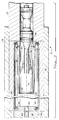
- a centering groove 40 is formed around forward bourrelet 38 and a centering band 42 is positioned in groove 40 as is best illustrated in Fig. 2.
- An obturator groove 44 is formed around rearward bourrelet 36 and an obturator band 46 is positioned in groove 44.
- a retaining groove 48 is also formed around aft bourrelet 36 rearward of obturator groove 44.
- a split retaining ring 50 is positioned in retaining groove 48 and cooperates with a similar retaining groove 52 formed in inner surface 30 of core tube 24 near its free end 26 to properly position sabot 34 and penetrator 32 in control tube 24.
- Split ring 50 and retaining grooves 48, 52 prevent movement of penetrator 32 and sabot 34 relative to control tube 24 and casing 12 when subjected to forces accompanying normal handling of round 10 prior to round 10 being fired.
- centering band 42 when round 10 is fired is to position forward bourrelet 38 and the forward portion of penetrator 32 in the center of control tube 24 with the axis of symmetry of penetrator 32 substantially aligned with axis of symmetry 18 of round 10 and of the bore of the gun barrel from which fired and to keep it so centered as sabot 34 and penetrator 32 are inserted into the bore of the gun fired and as they travel down the bore to the gun barrel's muzzle.
- obturator band 46 The primary function of obturator band 46 is to prevent ignition products produced by the burning propellant, both booster and main, of round 10 from flowing past sabot 34 as sabot 34 and penetrator 32 accelerate down control tube 24 and the barrel of the gun from which round 10 is fired.
- a primer 54 is mounted in rear seal 20 and is substantially centered on axis 18.
- a forward ring of consolidated main propellant 56 is positioned around the tapered outer surface 58 of control tube 24 and in substantial contact with surface 58.
- a rearward, or aft cylindrical ring of consolidated main propellant 60 is positioned within casing 12 between rear seal 20 and the forward ring of main propellant 56.
- a loose granular booster propellant 62 is positioned in the space defined by rear seal 20, the inner cylindrical surface 64 of the aft cylindrical ring of main propellant 60, rearward bourrelet 36, and the rearward portion 66 of penetrator 32 which includes the stabilizing fins 68.
- booster propellant 62 is a granular propellant such as a single base, single perforation military grade propellant which facilitates loading booster propellant 62 into round 10, and main propellant rings 56, 60 are made by consolidating into an annulus, or ring, of the proper dimensions a single base single perforation military grade propellant.
- the central opening in front seal 22 is closed by environmental seal 63 which is made of a suitable material, such as aluminum foil. The function of seal 63 is to prevent elements of the environment external to round 10 such as moisture, dirt, etc. from entering round 10 and adversely impacting the performance of the round.
- conventional gun 70 has its rifled barrel 72 fitted into breech block 74.
- Chamber liner 76 is positioned within breech block 74 aft of barrel 72.
- Round 10 is inserted into chamber 78 of gun 70 defined by the inner surface of chamber liner 76 through breech opening 80 in breech block 74; for example.
- bolt 82 closes opening 80.
- Centrally located in bolt 82 is a conventional firing mechanism 83.
- firing mechanism 83 could drive a firing pin into primer 54 or discharge an electrical current through primer 54 to initiate primer 54 which when initiated ignites booster charge 62.
- Pressure of the gases produced by burning booster charge 62 act on the aft bourrelet 36 of sabot and the portions of penetrator 32 rearward of aft bourrelet 36 to accelerate projectile 32 and sabot 34 along a trajectory substantially coinciding with axis 18 of round 10.
- the initial trajectory, or path, of penetrator 32 and sabot 34 is determined by core tube 24.
- the forces acting on projectile 32 and sabot 34 accelerate them down control tube 24 toward front seal 22 of round 10 and into the bore 84 of barrel 72.
- Obturator band 46 on aft bourrelet 36 of sabot 34 when it is within bore 84 of barrel 72 prevents gases produced by the ignited main propellant 86 which includes forward ring 56 and aft ring 60 and booster propellant 62 from flowing past bourrelet 36 so that sabot 34 and projectile 32 are accelerated to the desired muzzle velocity.
- the longitudinal axis of bore 84 substantially coincides with the axis 18 of round 10.
- control tube 24 is secured only to front seal 16 of casing 12 and its length is such that only a small portion of tube 24 extends aft of obturator band 46, no ignition ports are formed through control tube 24 to determine when the main propellant charge 86 which includes forward ring 56 and aft ring 60 is ignited by booster propellant 62.
- main propellant charge 86 is pressurized and ignited earlier which improves the ballistic repeatability of rounds 10.
- control tube 24 By using control tube 24 to guide sabot 34 and projectile 32 during that portion of the movement of sabot 34 during which it aft bourrelet 36 remains in contact with control tube 24, deviations of sabot 34 and projectile 32 from the desired trajectory are minimized. Further, no significantly unbalanced forces are applied to the structure of projectile 32 particularly aft of rearward bourrelet 36 of projectile 32 except those accelerating projectile 32 along axis 18, forces which projectile 32 and sabot 34 are designed to withstand.
- control tube 24 As pointed out above the thickness of side walls 87 of control tube 24 increases from its free, or unsupported, end 26 to its forward end 28 by which control tube 24 is secured to front seal 16.
- control tube 24 is tapered is that control tube 24 must be able to withstand the rapidly increasing pressure of the gases produced by burning propellant 62, 86, or chamber pressure, acting on outer surface 58 of control tube 24 forward of obturator band 46 on the rear bourrelet 36 of sabot 34.
- the pressure acting on the decreasing portion of control tube is a function of time beginning when round 10 is fired.
- the position of obturator band 46 on aft bourrelet 36 within control tube 24 is also a function of time beginning when round 10 is fired.
- the minimum thickness of side walls 87 of control tube 24 at any point along its length is, therefore, a function of the position of obturator band 46 within control tube 24 and of the chamber pressure, both of which are functions of time.
- the length of control tube 24 is minimized by making it just long enough to include obturator band 46 and retaining groove 48 of aft bourrelet 36 within control tube 24 when round 10 is assembled, and any time prior to round 10 being fired.
- Tapered control tube 24 is a minimum volume solution to this problem and is calculated using interior ballistic measurements which establish the pressure that control tube 24 must withstand at any instant of time after firing. Estimates of projectile motion establish the position of obturator band 46 and thus, the portion of the control tube 24 subject to radial inward pressure at each such instant of time. Text book equations are used to determine the thickness of the walls of the control tube 24 forward of obturator band 46 at each such instant of time to withstand the pressure until obturator band 46 clears control tube 24.
- Tapered control tube 24 prevents the pressure of the burning propellant acting on control tube 24 in front of obturator band 46 as it moves through control tube 24 from causing control tube 24 to collapse, or to apply excessive pressure to sabot 34, the occurrence of either of which would have a deleterious impact on the operation of the gun while minimizing the volume occupied by control tube 34.
- ablative package 88 which contains a suitable ablative grease for lubricating bore 84 of gun barrel 72.
- Lubricant 88 enters the interior of control tube 24, through a plurality of bores, or openings, 90 formed in control tube 24.
- the pressure of the gases produced by the burning propellants 62, 86 within casing 12 increases when round 10 is fired, the pressure quickly reaches a value where it is sufficient to force the ablative grease 88, typically a silicone grease, through bores 90 into control tube 24.
- Grease 88 is transported by sabot 34 into bore 84 of barrel 72 to coat the inner surface of barrel 72.
- the use of such a grease has the advantage of reducing the wear of the inner surface of barrel 72, and thus increases the number of rounds that can be fired by gun 70 before barrel 72 needs to be replaced.
- control tube 24, casing 12 and end seals 20, 22 are made of high carbon steel.
- Round 10 is assembled by attaching casing 12 to front seal 22 by a plurality of spring clips 92 which are attached to the front portion 16 of casing 12.
- Control tube 24 may be secured to front seal 22 by a threaded connection.
- Projectile 32 and sabot are positioned in control tube 24 and held in place by split retaining ring 50 which occupies part of retaining groove 48 of aft bourrelet 36 and part of retaining groove 52 of control tube 24.
- Ablative package 88 is placed around control tube 24, within casing 12, and adjacent to front seal 22.
- Forward ring 56 of main propellant charge 86 is positioned immediately aft of lubricating package 88, with aft ring 60 of main propellant 86 being positioned rearward of ring 56.
- the space defined by the inner surface 64 of aft ring 60 not occupied by projectile 32 and sabot 34 is filled to the desired extent with booster propellant 62.
- the rear end of casing 12 is closed by securing rear seal 20 and igniter 54 to the rear portion 14 of casing 12 by spring clips 94, for example, which are similar in structure and function to spring clips 92. All joints between the seals 20, 22 and casing 12 are environmentally sealed by a sealant such as a room temperature vulcanizing silicone which is not illustrated, and the opening 96 in front seal 22 is closed by environmental seal 63.
- the forwardly mounted full tapered caliber control tube 12 of cased telescoped ammunition round 10 of this invention which is secured only to the forward seal 22 of casing 12 provides a control tube of minimum length and which occupies a minimum amount of the limited space available with cased telescoped round 10.
- Tapered control tube 24 is strong enough to resist collapse forward of obturating band 46 of aft bourrelet 36 of sabot 34 and to prevent excessive inward radial pressure from being applied to sabot 34 and penetrator 32 as the pressure of the gas produced by the burning propellants 62, 86 increases while concurrently sabot 34 and projectile 32 are being driven forward through control tube 24.
- tapered control tube 24 provides space for a package of ablative grease 88 to be located forward of main propellant 86 while also increasing the volume within round 10 that can be occupied by propellant 62, 86 to increase the muzzle velocity of each round.
Landscapes
- Engineering & Computer Science (AREA)
- General Engineering & Computer Science (AREA)
- Portable Nailing Machines And Staplers (AREA)
Applications Claiming Priority (2)
| Application Number | Priority Date | Filing Date | Title |
|---|---|---|---|
| US07/613,255 US5063852A (en) | 1990-11-14 | 1990-11-14 | Forward full caliber control tube for a cased telescoped ammunition round |
| US613255 | 1990-11-14 |
Publications (2)
| Publication Number | Publication Date |
|---|---|
| EP0489283A2 true EP0489283A2 (fr) | 1992-06-10 |
| EP0489283A3 EP0489283A3 (en) | 1993-01-20 |
Family
ID=24456526
Family Applications (1)
| Application Number | Title | Priority Date | Filing Date |
|---|---|---|---|
| EP19910119332 Withdrawn EP0489283A3 (en) | 1990-11-14 | 1991-11-13 | Forward full caliber control tube for a cased telescoped ammunition round |
Country Status (4)
| Country | Link |
|---|---|
| US (1) | US5063852A (fr) |
| EP (1) | EP0489283A3 (fr) |
| CA (1) | CA2055102A1 (fr) |
| NO (1) | NO914424L (fr) |
Cited By (1)
| Publication number | Priority date | Publication date | Assignee | Title |
|---|---|---|---|---|
| CN110806299A (zh) * | 2019-08-23 | 2020-02-18 | 西北核技术研究院 | 一种将重金属长杆弹发射到超高速的小口径弹托 |
Families Citing this family (6)
| Publication number | Priority date | Publication date | Assignee | Title |
|---|---|---|---|---|
| FR2679993B1 (fr) * | 1991-07-31 | 1995-02-24 | Giat Ind Sa | Munition, en particulier du type telescope. |
| DE69502041T2 (de) * | 1994-02-28 | 1998-12-17 | Alliant Techsystems Inc., Hopkins, Minn. | Mit einer Hülse versehene teleskopische Patrone die kein Leitrohr hat |
| US6575097B1 (en) * | 2002-07-29 | 2003-06-10 | The United States Of America As Represented By The Secretary Of The Army | Large caliber case telescoped ammunition |
| US20050016413A1 (en) * | 2003-07-25 | 2005-01-27 | Giat Industries | Sub-calibred projectiles with multiple supports |
| WO2006110151A1 (fr) * | 2004-06-09 | 2006-10-19 | United Defense Lp | Dispositif de prevention de recul dans la chambre de projectile |
| US20090308274A1 (en) * | 2008-06-11 | 2009-12-17 | Lockheed Martin Corporation | Integrated Pusher Plate for a Canister- or Gun-Launched Projectile and System Incorporating Same |
Family Cites Families (7)
| Publication number | Priority date | Publication date | Assignee | Title |
|---|---|---|---|---|
| DE3277982D1 (en) * | 1981-08-18 | 1988-02-18 | Secr Defence Brit | Wear reducing projectile |
| US4715284A (en) * | 1986-11-24 | 1987-12-29 | Ford Aerospace & Communications Corp. | Telescoped ammunition construction for reducing barrel erosion |
| FR2624868B1 (fr) * | 1987-12-18 | 1990-08-31 | Poudres & Explosifs Ste Nale | Materiaux composites a pouvoir lubrifiant, leur procede de fabrication et elements anti-erosifs pour systeme d'arme a tube constitues a partir de ces materiaux |
| US4802415A (en) * | 1987-12-28 | 1989-02-07 | Ford Aerospace Corporation | Telescoped ammunition round having subcaliber projectile sabot with integral piston |
| US4846069A (en) * | 1988-02-10 | 1989-07-11 | Honeywell Inc. | Cased telescoped ammunition having features augmenting cartridge case end cap retention and retraction |
| US4858533A (en) * | 1988-05-06 | 1989-08-22 | Honeywell Inc. | Cased telescoped ammunition round for a fin stabilized projectile |
| US4967668A (en) * | 1989-10-16 | 1990-11-06 | Honeywell Inc. | Puller sabot for long rod projectiles |
-
1990
- 1990-11-14 US US07/613,255 patent/US5063852A/en not_active Expired - Fee Related
-
1991
- 1991-11-07 CA CA002055102A patent/CA2055102A1/fr not_active Abandoned
- 1991-11-12 NO NO91914424A patent/NO914424L/no unknown
- 1991-11-13 EP EP19910119332 patent/EP0489283A3/en not_active Withdrawn
Cited By (1)
| Publication number | Priority date | Publication date | Assignee | Title |
|---|---|---|---|---|
| CN110806299A (zh) * | 2019-08-23 | 2020-02-18 | 西北核技术研究院 | 一种将重金属长杆弹发射到超高速的小口径弹托 |
Also Published As
| Publication number | Publication date |
|---|---|
| US5063852A (en) | 1991-11-12 |
| CA2055102A1 (fr) | 1992-05-15 |
| EP0489283A3 (en) | 1993-01-20 |
| NO914424D0 (no) | 1991-11-12 |
| NO914424L (no) | 1992-05-15 |
Similar Documents
| Publication | Publication Date | Title |
|---|---|---|
| US11402187B2 (en) | Polymer projectile having an integrated driving band | |
| US5492063A (en) | Reduced energy cartridge | |
| EP0129777B1 (fr) | Munition | |
| US4712465A (en) | Dual purpose gun barrel for spin stabilized or fin stabilized projectiles and gun launched rockets | |
| EP2801784B1 (fr) | Projectile | |
| US5708231A (en) | Delayed release cartridge for a firearm | |
| US20030019385A1 (en) | Subsonic cartridge for gas-operated automatic and semiautomatic weapons | |
| US11725915B2 (en) | Ammunition cartridge | |
| US5834681A (en) | Reloadable high-low pressure ammunition cartridge | |
| US5880397A (en) | Selectable cartridge | |
| US5804759A (en) | Hunting bullet having a telescoping flechette and comprising a sub-projectile connected to a launcher | |
| EP0171534B1 (fr) | Intercepteur de balle et déflecteur de balle pour grenade à fusil | |
| US4858533A (en) | Cased telescoped ammunition round for a fin stabilized projectile | |
| EP0669513A1 (fr) | Munition télescopique à douille n'ayant pas un tube de contrôle | |
| US5063852A (en) | Forward full caliber control tube for a cased telescoped ammunition round | |
| US4611540A (en) | Mortar ammunition | |
| US11473883B1 (en) | Caseless tapered-bore ammunition and firearm | |
| US2091635A (en) | Projectile | |
| US5589658A (en) | Sabot with controlled separation of the elements for subcaliber projectiles | |
| EP0238155A1 (fr) | Munition pour armes à feu | |
| US20070272111A1 (en) | Low Energy Training Cartridge | |
| US20080257192A1 (en) | High Muzzle Velocity Projectiles and Barrels | |
| CN1398341A (zh) | 退弹壳装置 | |
| USH1353H (en) | Velocity enhancing projectile sabot | |
| US3848530A (en) | Shot obturation system for fully telescoped caseless ammunition |
Legal Events
| Date | Code | Title | Description |
|---|---|---|---|
| PUAI | Public reference made under article 153(3) epc to a published international application that has entered the european phase |
Free format text: ORIGINAL CODE: 0009012 |
|
| AK | Designated contracting states |
Kind code of ref document: A2 Designated state(s): CH DE FR GB IT LI NL |
|
| PUAL | Search report despatched |
Free format text: ORIGINAL CODE: 0009013 |
|
| AK | Designated contracting states |
Kind code of ref document: A3 Designated state(s): CH DE FR GB IT LI NL |
|
| STAA | Information on the status of an ep patent application or granted ep patent |
Free format text: STATUS: THE APPLICATION HAS BEEN WITHDRAWN |
|
| 18W | Application withdrawn |
Withdrawal date: 19930714 |