EP0489315A2 - Optischer Isolator - Google Patents
Optischer Isolator Download PDFInfo
- Publication number
- EP0489315A2 EP0489315A2 EP91119905A EP91119905A EP0489315A2 EP 0489315 A2 EP0489315 A2 EP 0489315A2 EP 91119905 A EP91119905 A EP 91119905A EP 91119905 A EP91119905 A EP 91119905A EP 0489315 A2 EP0489315 A2 EP 0489315A2
- Authority
- EP
- European Patent Office
- Prior art keywords
- thickness
- rutile
- light
- birefringent crystal
- birefringent
- Prior art date
- Legal status (The legal status is an assumption and is not a legal conclusion. Google has not performed a legal analysis and makes no representation as to the accuracy of the status listed.)
- Withdrawn
Links
Images


Classifications
-
- G—PHYSICS
- G02—OPTICS
- G02F—OPTICAL DEVICES OR ARRANGEMENTS FOR THE CONTROL OF LIGHT BY MODIFICATION OF THE OPTICAL PROPERTIES OF THE MEDIA OF THE ELEMENTS INVOLVED THEREIN; NON-LINEAR OPTICS; FREQUENCY-CHANGING OF LIGHT; OPTICAL LOGIC ELEMENTS; OPTICAL ANALOGUE/DIGITAL CONVERTERS
- G02F1/00—Devices or arrangements for the control of the intensity, colour, phase, polarisation or direction of light arriving from an independent light source, e.g. switching, gating or modulating; Non-linear optics
- G02F1/01—Devices or arrangements for the control of the intensity, colour, phase, polarisation or direction of light arriving from an independent light source, e.g. switching, gating or modulating; Non-linear optics for the control of the intensity, phase, polarisation or colour
- G02F1/09—Devices or arrangements for the control of the intensity, colour, phase, polarisation or direction of light arriving from an independent light source, e.g. switching, gating or modulating; Non-linear optics for the control of the intensity, phase, polarisation or colour based on magneto-optical elements, e.g. exhibiting Faraday effect
- G02F1/093—Devices or arrangements for the control of the intensity, colour, phase, polarisation or direction of light arriving from an independent light source, e.g. switching, gating or modulating; Non-linear optics for the control of the intensity, phase, polarisation or colour based on magneto-optical elements, e.g. exhibiting Faraday effect used as non-reciprocal devices, e.g. optical isolators, circulators
-
- G—PHYSICS
- G02—OPTICS
- G02F—OPTICAL DEVICES OR ARRANGEMENTS FOR THE CONTROL OF LIGHT BY MODIFICATION OF THE OPTICAL PROPERTIES OF THE MEDIA OF THE ELEMENTS INVOLVED THEREIN; NON-LINEAR OPTICS; FREQUENCY-CHANGING OF LIGHT; OPTICAL LOGIC ELEMENTS; OPTICAL ANALOGUE/DIGITAL CONVERTERS
- G02F2203/00—Function characteristic
- G02F2203/06—Polarisation independent
Definitions
- This invention relates to optical isolators for use in optical fiber communication or in optical fiber amplifiers.
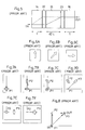
- a known optical isolator of little polarization dependence is formed of birefringent crystals and Faraday elements. A construction of such an optical isolator will be described with reference to Fig. 1.
- rutile TiO2
- the optical isolator shown in Fig. 1 includes a rutile plate 11, a Faraday element 21, a rutile plate 12 and a rutile plate 13 arranged in the stated order from a light incident end.
- the rutile plate 11 has a thickness ⁇ 2 ⁇ t, while the rutile plates 12 and 13 have a thickness t.
- the rutile plates 11, 12 and 13 have optic axes (C axes) oriented as shown in Figs. 2A, 2B and 2C when seen from the light incident end, respectively.
- the rutile plate 12 has an optic axis extending in a direction rotated 45 o clockwise from the optic axis of the rutile plate 11.
- the rutile plate 13 has an optic axis extending in a direction rotated 135 o clockwise from the optic axis of the rutile plate 11.
- the two light components exiting the rutile plate 12 enters the rutile plate 13.
- the component entering at position P2 is refracted as an extraordinary light component and exits at position P3 as shown in Fig 3E.
- Position P3 is located 45 o rightward and downward from position P2, and the distance therebetween is proportional to the thickness t of the rutile plate 13.
- the component entering at position P3 is an ordinary light component which passes straight through the rutile plate 13 without being refracted, and exits at position P3. Consequently, the two polarized light components coincide at exit position P3.
- Fig. 4 shows the positional relationship between the polarized components of the incident light, and sequence of variations occurring in the relationship until exit from the optical isolator.
- the above optical isolator is used in series connection with another one-stage type optical isolator as shown in Fig. 1, in order to increase a loss in the reverse direction.
- This optical isolator includes a rutile plate 14, a Faraday element 22, a rutile plate 15, a Faraday element 23 and a rutile plate 16 arranged in the stated order from a light incident end.
- the rutile plates 14 and 16 have a thickness t, while the rutile plate 15 has a thickness ⁇ 2 ⁇ t.
- the rutile plates 14, 15 and 16 have optic axes oriented as shown in Figs. 6A, 6B and 6C when seen from the light incident end, respectively. That is, the rutile plate 15 has an optic axis extending in a direction rotated 45 o clockwise from the optic axis of the rutile plate 14.
- the rutile plate 16 has an optic axis extending in a direction rotated 90 o clockwise from the optic axis of the rutile plate 14.
- the two polarized light components exiting the rutile plate 15 have the respective planes of polarization rotated 45 o in the Faraday element 23. Since, as noted above, the positional relationship between the two light components does not change, the two light components entering the rutile plate 16 have planes of polarization and incident positions as shown in Fig. 7E.
- the component entering at position P2 is refracted as an extraordinary light component and exits at position P3 as shown in Fig. 7F.
- Position P3 is located rightward from position P2, and the distance therebetween is proportional to the thickness t of the rutile plate 16.
- the component entering at position P3 is an ordinary light component which passes straight through the rutile plate 16 without being refracted, and exits at position P3. Consequently, the two polarized light components coincide at exit position P3.
- Fig. 8 shows the positional relationship between the polarized components of the incident light, and sequence of variations occurring in the relationship until exit from the optical isolator.
- the optical isolator of Fig. 1 has the disadvantage that the two polarized light components travel through different optical path lengths from entry to the isolator to exit therefrom as shown in Fig. 4. This presents no problem if incident light is in the form of parallel rays. However, convergent or divergent light would form different focal points as a result of the different optical path lengths, which increases a coupling loss between the optical isolator and an exit side optical fiber. Further, this optical isolator is connected in series with another isolator of the same type, which results in a complicated construction with an increased number of optical elements constituting the optical isolators.
- the optical isolator of Fig. 5 has a relatively simple construction. However, this isolator also has the disadvantage of providing different optical path lengths for the two polarized light components as shown in Fig. 8.
- This invention has been made having regard to the state of the art noted above, and its object is to provide an improved optical isolator in which the two separate polarized light components travel through the same optical path length, so that no inconvenience occurs with convergent or divergent light.
- an optical isolator having a combination of birefringent crystals and Faraday elements, the optical isolator comprising, arranged along an optical axis: a first birefringent crystal; a first Faraday element for rotating a plane of polarization 45 o ; a second birefringent crystal having an optic axis rotated 45 o with respect to the first birefringent crystal, and a thickness ⁇ 2 times a thickness of the first birefringent crystal; a third birefringent crystal having an optic axis rotated 135 o with respect to the first birefringent crystal, and a thickness ⁇ 2 times the thickness of the first birefringent crystal; a second Faraday element for rotating the plane of polarization 45 o ; and a fourth birefringent crystal having an optic axis rotated 180 o with respect to the first birefringent crystal, and a thickness equal to the thickness of the first
- the first and second birefringent crystals and the first Faraday element interposed therebetween constitute a first-stage isolator
- the third and fourth birefringent crystals and the second Faraday element interposed therebetween constitute a second-stage isolator.
- the first-stage isolator and second-stage isolator provide passages of light in a conversed relationship, whereby different polarized light components travel through the same optical path length.
- an optical isolator having a combination of birefringent crystals and Faraday elements, the optical isolator comprising, arranged along an optical axis: a first birefringent crystal; a first Faraday element for rotating a plane of polarization 45 o ; a second birefringent crystal having an optic axis rotated 45 o with respect to the first birefringent crystal, and a thickness (1+ ⁇ 2) times a thickness of the first birefringent crystal; a second Faraday element for rotating the plane of polarization 45 o ; a third birefringent crystal having an optic axis rotated 90 o with respect to the first birefringent crystal, and a thickness (1+ ⁇ 2) times the thickness of the first birefringent crystal; a third Faraday element for rotating the plane of polarization 45 o ; and a fourth birefringent crystal having an optic axis rotated 135 o with
- the first and second birefringent crystals and the first Faraday element interposed therebetween constitute a first-stage isolator
- the second and third birefringent crystals and the second Faraday element interposed therebetween constitute a second-stage isolator
- the third and fourth birefringent crystals and the third Faraday element interposed therebetween constitute a third-stage isolator.
- the birefringent crystals are paired in a thickness ratio of 1:(1+ ⁇ 2) to provide the same optical path length for different polarized light components.
- optical isolators may be constructed relatively easily for providing an equal optical path length for two separated light components to travel to the exit end. This construction is free from displaced focal points resulting from convergent or divergent light, thereby diminishing a loss occurring where the optical isolator is coupled to an optical fiber.
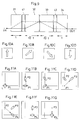
- an optical isolator employs rutile (TiO2) as birefringent crystals, and includes four rutile plates 31, 32, 33 and 34 and two Faraday elements 41 and 42. These components are arranged in series along an optical axis in the order of rutile plate 31, Faraday element 41, rutile plate 32, rutile plate 33, Faraday element 42 and rutile plate 34.
- the rutile plates 31, 32, 33 and 34 have optic axes oriented as shown by arrows in Figs. 10A through 10D when seen from a light incident end, respectively.
- the rutile plate 32 has an optic axis extending in a direction rotated 45 o clockwise from the optic axis of the rutile plate 31.
- the rutile plate 33 has an optic axis extending in a direction rotated 135 o clockwise from the optic axis of the rutile plate 31.
- the rutile plate 34 has an optic axis extending in a direction rotated 180 o clockwise from the optic axis of the rutile plate 31.
- the rutile plates 31, 32, 33 and 34 have thicknesses t, ⁇ 2 ⁇ t, ⁇ 2 ⁇ t and t, respectively.
- the rutile plate 32 has the optic axis as shown by the arrow in Fig. 10B, and the thickness ⁇ 2 ⁇ t.
- the component entering at position P1 is refracted as an extraordinary light component as in the first rutile plate 31.
- Position P3 is located 45 o upward and rightward from position P1, and the distance therebetween is proportional to ⁇ 2 ⁇ t.
- the light component entering at the other position P2 is an ordinary light component which passes straight through the rutile plate 32 without being refracted, and exits at position P2.
- the rutile plates 31, 32, 33 and 34 all have the optic axes and plate surfaces forming the same angle, i.e. have the same angle of separation.
- the two polarized light components exiting the rutile plate 32 enter the rutile plate 33.
- This rutile plate 35 have the optic axis as shown by the arrow in Fig. 10C, and the thickness ⁇ 2 ⁇ t.
- the component entering at position P2 is refracted as an extraordinary light component and exits at position P4 as shown in Fig. 11E.
- Position P4 is located 45 o rightward and downward from position P2, and the distance therebetween is proportional to ⁇ 2 ⁇ t.
- the component entering at position P3 is an ordinary light component which passes straight through the rutile plate 33 without being refracted, and exits at position P3.
- the two light components exiting the rutile plate 33 travels through the Faraday element 42 where the respective planes of polarization are rotated 45 o , and enter the next rutile plate 34.
- the two light components entering the rutile plate 34 have positions and planes of polarization as shown in Fig. 11F.
- This rutile plate 34 has the optic axis extending as shown by the arrow in Fig. 10D, and the light component entering at position P3 is refracted downward as an extraordinary light component.
- the angle of refraction is the same as in the other rutile plates 31, 32 and 33.
- the displacement due to the refraction is proportional to the thickness of the rutile plate. Since this rutile plate 34 have the thickness t, the displacement occurs through a distance proportional to t. Consequently, the two polarized light components coincide at exit position P3 (Fig. 11G).
- Fig. 12 shows the incident and exit points seen from the end of light incidence.
- the light component refracted upward by the first rutile plate 31 moves from position P1 to position P2. Subsequently, this light component is refracted 45 o rightward and downward by the rutile plate 33 to move to position P4.
- the distance between positions P1 and P2 is proportional to the thickness t, while the distance between positions P2 and P4 is proportional to the thickness ⁇ 2 ⁇ t.
- the light component traveling straight through the rutile plate 31 is refracted 45 o upward and rightward by the rutile plate 32, and the amount of displacement (i.e.
- the extraordinary light and ordinary light have optical path lengths Ne and No through the rutile plates 32 and 33 having the thickness ⁇ 2 ⁇ t, and optical path lengths Ne' and No' through the rutile plates 31 and 34 having the thickness t, respectively
- the total path length of the light component moving from position P1 through position P2 to position P4 is; Ne' + No + Ne + No' and that of the light component moving from position P1 through position P3 to position P4 is; No' + Ne + No + Ne'.
- the two light components travel through an equal optical path length.
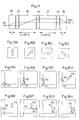
- an optical isolator employs rutile (TiO2) as birefringent crystals, and includes four rutile plates 35, 36, 37 and 38 and three Faraday elements 43, 44 and 45. These components are arranged in series along an optical axis in the order of rutile plate 35, Faraday element 43, rutile plate 36, Faraday element 44, rutile plate 37, Faraday element 45 and rutile plate 38.
- the rutile plates 35, 36, 37 and 38 have optic axes oriented as shown by arrows in Figs. 15A through 15D when seen from a light incident end, respectively.
- the rutile plate 36 has an optic axis extending in a direction rotated 45 o clockwise from the optic axis of the rutile plate 35.
- the rutile plate 37 has an optic axis extending in a direction rotated 90 o clockwise from the optic axis of the rutile plate 35.
- the rutile plate 38 has an optic axis extending in a direction rotated 135 o clockwise from the optic axis of the rutile plate 35.
- the rutile plates 35, 36, 37 and 38 have thicknesses t, (1+ ⁇ 2)t, (1+ ⁇ 2)t and t, respectively.
- the rutile plate 36 has the optic axis as shown by the arrow in Fig. 15B, and the thickness (1+ ⁇ 2)t.
- the component entering at position P1 is refracted as an extraordinary light component as in the first rutile plate 35.
- the component entering at position P1 exits at position P3 as shown in Fig. 16D.
- Position P3 is located 45 o upward and rightward from position P1, and the distance therebetween is proportional to (1+ ⁇ 2)t.
- the light component entering at the other position P2 is an ordinary light component which passes straight through the rutile plate 36 without being refracted, and exits at position P2.
- the rutile plates 35, 36, 37 and 38 all have the optic axes and plate surfaces forming the same angle, i.e. have the same angle of separation.
- the two polarized light components exiting the rutile plate 36 enters the Faraday element 44 where the respective planes of polarization are rotated 45 o .
- the positional relationship between the two light components does not change, and the two light components exit the Faraday element 44 as shown in Fig. 16E.
- the light components exiting the Faraday element 44 enter the rutile plate 37.
- This rutile plate 37 have the optic axis as shown by the arrow in Fig. 15C, and the thickness (1 ⁇ 2)t.
- the component entering at position P2 is refracted as an extraordinary light component and exits at position P4 as shown in Fig. 16F.
- Position P4 is located rightward from position P2, and the distance therebetween is proportional to (1+ ⁇ 2)t.
- the component entering at position P3 is an ordinary light component which passes straight through the rutile plate 37 without being refracted, and exits at position P3.
- the two light components exiting the rutile plate 37 travels through the Faraday element 45 where the respective planes of polarization are rotated 45 o , and enter the next rutile plate 38.
- the light components entering the rutile plate 38 have positions and planes of polarization as shown in Fig. 16G.
- This rutile plate 38 has the optic axis extending as shown by the arrow in Fig. 15D, and the light component entering at position P3 is refracted rightward and downward as an extraordinary light component.
- the angle of refraction is the same as in the other rutile plates 35, 36 and 37.
- the displacement due to the refraction is proportional to the thickness of the rutile plate. Since this rutile plate 38 have the thickness t, the displacement occurs through a distance proportional to t. Consequently, the two polarized light components coincide at exit position P4 (Fig. 16H).
- Fig. 17 shows the incident and exit points seen from the end of light incidence.
- the light component refracted upward by the first rutile plate 35 moves from position P1 to position P2. Subsequently, this light component is refracted rightward by the rutile plate 37 to move to position P4.
- the distance between positions P1 and P2 is proportional to the thickness t, while the distance between positions P2 and P4 is proportional to the thickness (1+ ⁇ 2)t.
- the light component traveling straight through the rutile plate 35 is refracted 45 o upward and rightward by the rutile plate 36, and the amount of displacement (i.e. distance between positions P1 and P3) is proportional to the thickness (1+ ⁇ 2)t.
- This light component is refracted rightward and downward by the rutile plate 38, and the amount of displacement (i.e. distance between positions P3 and P4) is proportional to the thickness t.
- the factor of proportionality is the same in all the cases, which is tan ⁇ ( ⁇ being an angle of separation, e.g. 5.8 o ).
- ⁇ being an angle of separation, e.g. 5.8 o .
- the fact that the respective light components become displaced in the same amount in directions at right angles to the optical axis means that both light components travel through an equal optical path length.
- a light component having a plane of polarization inclined 45 o counterclockwise is an ordinary light in all of the rutile plates 35, 36, 37 and 38 and is therefore not refracted.
- this light component does not shift from the incidence position P4 but exits at this position P4.
- These exit positions P4 and P7 are different from each other, and are far from the incidence position P1 of the light traveling forward. Thus, isolation characteristics are obtained which cause no loss of the light traveling in the forward direction but a great loss of the light traveling in the reverse direction.
- the Faraday elements may have varied thicknesses to provide slightly differentiated wavelengths with the respective planes of polarization rotated 45 o . Then, each of the plural-stage isolators (the two-stage isolator in the first embodiment, and the three-stage isolator in the second embodiment) may be operable over a wide wavelength range.
- birefringent crystals may be used instead.
Landscapes
- Physics & Mathematics (AREA)
- Nonlinear Science (AREA)
- Engineering & Computer Science (AREA)
- Power Engineering (AREA)
- General Physics & Mathematics (AREA)
- Optics & Photonics (AREA)
Applications Claiming Priority (4)
| Application Number | Priority Date | Filing Date | Title |
|---|---|---|---|
| JP130719/90 | 1990-11-30 | ||
| JP13071990U JP2508741Y2 (ja) | 1990-11-30 | 1990-11-30 | 光アイソレ―タ |
| JP1990130718U JPH0712970Y2 (ja) | 1990-11-30 | 1990-11-30 | 光アイソレータ |
| JP130718/90 | 1990-11-30 |
Publications (2)
| Publication Number | Publication Date |
|---|---|
| EP0489315A2 true EP0489315A2 (de) | 1992-06-10 |
| EP0489315A3 EP0489315A3 (en) | 1992-11-19 |
Family
ID=26465778
Family Applications (1)
| Application Number | Title | Priority Date | Filing Date |
|---|---|---|---|
| EP19910119905 Withdrawn EP0489315A3 (en) | 1990-11-30 | 1991-11-22 | Optical isolator |
Country Status (2)
| Country | Link |
|---|---|
| US (1) | US5237445A (de) |
| EP (1) | EP0489315A3 (de) |
Cited By (7)
| Publication number | Priority date | Publication date | Assignee | Title |
|---|---|---|---|---|
| EP0525208A4 (en) * | 1991-02-20 | 1993-03-31 | Sumitomo Electric Industries, Ltd. | Optical isolator |
| EP0552783A3 (en) * | 1992-01-22 | 1993-11-10 | Nec Corp | Optical isolator device |
| EP0611980A1 (de) * | 1993-02-17 | 1994-08-24 | Sumitomo Electric Industries, Ltd. | Optischer Isolator |
| EP0653660A1 (de) * | 1993-11-12 | 1995-05-17 | AT&T Corp. | Optischer Isolator mit reduziertem "Walk-off" |
| EP0653661A1 (de) * | 1993-11-12 | 1995-05-17 | AT&T Corp. | Optischer Isolator mit verringerter Polarisationsmodendispersion |
| EP0665452A1 (de) * | 1994-01-28 | 1995-08-02 | Namiki Precision Jewel Co., Ltd. | Polarisationsunabhängiger optischer Isolator |
| DE19725720A1 (de) * | 1997-06-18 | 1998-12-24 | Alsthom Cge Alcatel | Optischer Isolator und Wellenlängenmuliplexer-Modul mit integriertem optischen Isolator |
Families Citing this family (24)
| Publication number | Priority date | Publication date | Assignee | Title |
|---|---|---|---|---|
| WO1993005429A1 (en) * | 1991-09-12 | 1993-03-18 | Fujitsu Limited | Optical device |
| US5631771A (en) * | 1991-09-19 | 1997-05-20 | Lucent Technologies Inc. | Optical isolator with polarization dispersion and differential transverse deflection correction |
| JPH08505961A (ja) * | 1993-01-21 | 1996-06-25 | イー−テック・ダイナミックス・インコーポレイテッド | 偏光モード分散の低い光学装置 |
| US5602673A (en) * | 1993-12-29 | 1997-02-11 | Lucent Technologies Inc. | Optical isolator without polarization mode dispersion |
| JP3153406B2 (ja) * | 1994-03-03 | 2001-04-09 | 松下電器産業株式会社 | 光回路及びそれを用いた光伝送システム |
| US5528415A (en) * | 1994-11-09 | 1996-06-18 | Duke University | Compact enhanced performance optical isolator using a faraday rotator |
| CA2148317C (en) * | 1995-05-01 | 1998-05-05 | Yihao Cheng | Optical circulator |
| US5734763A (en) * | 1996-09-04 | 1998-03-31 | Hewlett-Packard Company | Compact two-by-n optical components based on bierfringent walk-off crystals |
| US5930418A (en) * | 1997-02-25 | 1999-07-27 | Hewlett-Packard Company | Optical assembly and method based on TEC fibres |
| US6026202A (en) * | 1997-02-25 | 2000-02-15 | Hewlett-Packard Company | Compact, low crosstalk, three-port optical circulator |
| US6088153A (en) * | 1997-06-26 | 2000-07-11 | Scientific-Atlanta, Inc. | Multi-functional optical isolator |
| US6088491A (en) * | 1998-02-13 | 2000-07-11 | Agilent Technologies, Inc. | Optical circulator |
| US6091866A (en) * | 1998-09-01 | 2000-07-18 | Cheng; Yihao | Optical isolator |
| US6167174A (en) * | 1998-10-27 | 2000-12-26 | Adc Telecommunications, Inc. | Multiple port, fiber optic isolator |
| US6288826B1 (en) * | 2000-01-05 | 2001-09-11 | Jds Uniphase Inc. | Multi-stage optical isolator |
| US6567578B1 (en) | 2000-02-16 | 2003-05-20 | Adc Telecommunications | Fiber optic device operating at two or more wavelengths |
| US6532321B1 (en) | 2000-02-16 | 2003-03-11 | Adc Telecommunications, Inc. | Fiber optic isolator for use with multiple-wavelength optical signals |
| JP2001349872A (ja) * | 2000-06-06 | 2001-12-21 | Shimadzu Corp | 磁気センサ |
| JP2002107670A (ja) * | 2000-10-03 | 2002-04-10 | Fdk Corp | 光サーキュレータ及び光スイッチ |
| WO2002069029A1 (en) * | 2001-02-28 | 2002-09-06 | Board Of Control Of Michigan Technological University | Magneto-photonic crystal isolators |
| US7453641B2 (en) * | 2001-10-30 | 2008-11-18 | Asml Netherlands B.V. | Structures and methods for reducing aberration in optical systems |
| US6995908B2 (en) * | 2001-10-30 | 2006-02-07 | Asml Netherlands B.V. | Methods for reducing aberration in optical systems |
| US20170176781A1 (en) * | 2015-12-18 | 2017-06-22 | Electro-Optics Technology, Inc. | Single and multi-stage high power optical isolators using a single polarizing element |
| US10718963B1 (en) | 2016-11-16 | 2020-07-21 | Electro-Optics Technology, Inc. | High power faraday isolators and rotators using potassium terbium fluoride crystals |
Family Cites Families (12)
| Publication number | Priority date | Publication date | Assignee | Title |
|---|---|---|---|---|
| JPS6049297B2 (ja) * | 1977-05-31 | 1985-11-01 | 日本電気株式会社 | 光アイソレ−タ |
| US4239329A (en) * | 1978-08-04 | 1980-12-16 | Nippon Telegraph And Telephone Public Corporation | Optical nonreciprocal device |
| JPS5624314A (en) * | 1979-08-06 | 1981-03-07 | Mitsubishi Electric Corp | Optical isolator |
| JPS57100410A (en) * | 1980-12-15 | 1982-06-22 | Fujitsu Ltd | Optical isolator |
| JPS5850512A (ja) * | 1981-09-21 | 1983-03-25 | Nippon Telegr & Teleph Corp <Ntt> | 光アイソレ−タ |
| CA1253726A (en) * | 1982-06-28 | 1989-05-09 | Masataka Shirasaki | Polarization rotation compensator and optical isolator using the same |
| JPS59176721A (ja) * | 1983-03-25 | 1984-10-06 | Fujitsu Ltd | 光アイソレ−タ |
| JPS60130934A (ja) * | 1983-12-20 | 1985-07-12 | Fujitsu Ltd | 光アイソレ−タ |
| EP0279412B1 (de) * | 1987-02-17 | 1993-09-29 | Hitachi Metals, Ltd. | Optischer Isolator |
| JPH02188715A (ja) * | 1989-01-18 | 1990-07-24 | Nec Corp | 光アイソレータ |
| US5033830A (en) * | 1989-10-04 | 1991-07-23 | At&T Bell Laboratories | Polarization independent optical isolator |
| US5052786A (en) * | 1990-03-05 | 1991-10-01 | Massachusetts Institute Of Technology | Broadband faraday isolator |
-
1991
- 1991-11-20 US US07/795,140 patent/US5237445A/en not_active Expired - Fee Related
- 1991-11-22 EP EP19910119905 patent/EP0489315A3/en not_active Withdrawn
Cited By (12)
| Publication number | Priority date | Publication date | Assignee | Title |
|---|---|---|---|---|
| EP0525208A4 (en) * | 1991-02-20 | 1993-03-31 | Sumitomo Electric Industries, Ltd. | Optical isolator |
| US5381261A (en) * | 1991-02-20 | 1995-01-10 | Sumitomo Electric Industries, Ltd. | Optical isolator |
| EP0691563A3 (de) * | 1991-02-20 | 1997-01-15 | Sumitomo Electric Industries | Optischer Isolator |
| EP0552783A3 (en) * | 1992-01-22 | 1993-11-10 | Nec Corp | Optical isolator device |
| US5835270A (en) * | 1992-01-22 | 1998-11-10 | Nec Corporation | Optical isolator device |
| EP0611980A1 (de) * | 1993-02-17 | 1994-08-24 | Sumitomo Electric Industries, Ltd. | Optischer Isolator |
| US5408491A (en) * | 1993-02-17 | 1995-04-18 | Sumitomo Electric Industries, Ltd. | Optical isolator |
| EP0653660A1 (de) * | 1993-11-12 | 1995-05-17 | AT&T Corp. | Optischer Isolator mit reduziertem "Walk-off" |
| EP0653661A1 (de) * | 1993-11-12 | 1995-05-17 | AT&T Corp. | Optischer Isolator mit verringerter Polarisationsmodendispersion |
| EP0665452A1 (de) * | 1994-01-28 | 1995-08-02 | Namiki Precision Jewel Co., Ltd. | Polarisationsunabhängiger optischer Isolator |
| DE19725720A1 (de) * | 1997-06-18 | 1998-12-24 | Alsthom Cge Alcatel | Optischer Isolator und Wellenlängenmuliplexer-Modul mit integriertem optischen Isolator |
| US6081635A (en) * | 1997-06-18 | 2000-06-27 | Alcatel | Microoptical module with a WDM filter and an optical isolator for fiber-optic amplifier systems |
Also Published As
| Publication number | Publication date |
|---|---|
| US5237445A (en) | 1993-08-17 |
| EP0489315A3 (en) | 1992-11-19 |
Similar Documents
| Publication | Publication Date | Title |
|---|---|---|
| US5237445A (en) | Optical isolator | |
| US5408354A (en) | Optical Isolator | |
| US5682446A (en) | Polarization mode dispersion-free circulator | |
| US5499307A (en) | Optical isolator and polarization splitter therefor | |
| US6636651B2 (en) | Four-port bidirectional optical circulator | |
| US6590706B1 (en) | Optical circulators using beam angle turners | |
| US5923470A (en) | Polarization beam splitter | |
| US5923472A (en) | 3-port optical circulator/switch with mirror | |
| US6249619B1 (en) | Optical isolator | |
| EP0552783B1 (de) | Optischer Isolator | |
| EP0591381A1 (de) | Adiabatischer polarisationsteiler. | |
| NL7905972A (nl) | Optische niet-reciproke inrichting. | |
| US5930422A (en) | Optical circulator | |
| US5936768A (en) | Optical passive device for an optical fiber amplifier and the optical amplifier | |
| US20040021940A1 (en) | Optical polarization rotating device | |
| US5872878A (en) | Partial optical circulators | |
| JP3368209B2 (ja) | 反射型光サーキュレータ | |
| EP0874263A1 (de) | Optischer Zirkulator | |
| US6549686B2 (en) | Reflective optical circulator | |
| US20020024729A1 (en) | Compact polarization insensitive circulators with simplified structure and low polarization mode dispersion | |
| JP2905847B2 (ja) | 光アイソレータ装置 | |
| EP1115025A2 (de) | Mehrstufiger optischer Isolator | |
| JPH0820623B2 (ja) | 光アイソレータ | |
| JPH11264954A (ja) | 光サーキュレータ及び光スイッチ | |
| WO2004104664A1 (en) | Polarization device |
Legal Events
| Date | Code | Title | Description |
|---|---|---|---|
| PUAI | Public reference made under article 153(3) epc to a published international application that has entered the european phase |
Free format text: ORIGINAL CODE: 0009012 |
|
| AK | Designated contracting states |
Kind code of ref document: A2 Designated state(s): DE FR GB |
|
| PUAL | Search report despatched |
Free format text: ORIGINAL CODE: 0009013 |
|
| AK | Designated contracting states |
Kind code of ref document: A3 Designated state(s): DE FR GB |
|
| 17P | Request for examination filed |
Effective date: 19930505 |
|
| 17Q | First examination report despatched |
Effective date: 19960125 |
|
| GRAG | Despatch of communication of intention to grant |
Free format text: ORIGINAL CODE: EPIDOS AGRA |
|
| GRAG | Despatch of communication of intention to grant |
Free format text: ORIGINAL CODE: EPIDOS AGRA |
|
| GRAH | Despatch of communication of intention to grant a patent |
Free format text: ORIGINAL CODE: EPIDOS IGRA |
|
| STAA | Information on the status of an ep patent application or granted ep patent |
Free format text: STATUS: THE APPLICATION IS DEEMED TO BE WITHDRAWN |
|
| 18D | Application deemed to be withdrawn |
Effective date: 19971020 |