EP0489331B1 - Soupape actionnée par son propre fluide et commandée par un électro-aimant - Google Patents
Soupape actionnée par son propre fluide et commandée par un électro-aimant Download PDFInfo
- Publication number
- EP0489331B1 EP0489331B1 EP91120095A EP91120095A EP0489331B1 EP 0489331 B1 EP0489331 B1 EP 0489331B1 EP 91120095 A EP91120095 A EP 91120095A EP 91120095 A EP91120095 A EP 91120095A EP 0489331 B1 EP0489331 B1 EP 0489331B1
- Authority
- EP
- European Patent Office
- Prior art keywords
- magnet armature
- magnet
- head piece
- valve
- differential piston
- Prior art date
- Legal status (The legal status is an assumption and is not a legal conclusion. Google has not performed a legal analysis and makes no representation as to the accuracy of the status listed.)
- Expired - Lifetime
Links
- 239000012530 fluid Substances 0.000 title abstract 2
- 125000006850 spacer group Chemical group 0.000 claims abstract description 14
- 239000000463 material Substances 0.000 claims description 3
- 229920001296 polysiloxane Polymers 0.000 claims description 2
- 239000012528 membrane Substances 0.000 description 11
- 238000005096 rolling process Methods 0.000 description 3
- 238000011084 recovery Methods 0.000 description 1
- 238000004073 vulcanization Methods 0.000 description 1
Images
Classifications
-
- F—MECHANICAL ENGINEERING; LIGHTING; HEATING; WEAPONS; BLASTING
- F16—ENGINEERING ELEMENTS AND UNITS; GENERAL MEASURES FOR PRODUCING AND MAINTAINING EFFECTIVE FUNCTIONING OF MACHINES OR INSTALLATIONS; THERMAL INSULATION IN GENERAL
- F16K—VALVES; TAPS; COCKS; ACTUATING-FLOATS; DEVICES FOR VENTING OR AERATING
- F16K31/00—Actuating devices; Operating means; Releasing devices
- F16K31/12—Actuating devices; Operating means; Releasing devices actuated by fluid
- F16K31/36—Actuating devices; Operating means; Releasing devices actuated by fluid in which fluid from the circuit is constantly supplied to the fluid motor
- F16K31/40—Actuating devices; Operating means; Releasing devices actuated by fluid in which fluid from the circuit is constantly supplied to the fluid motor with electrically-actuated member in the discharge of the motor
- F16K31/406—Actuating devices; Operating means; Releasing devices actuated by fluid in which fluid from the circuit is constantly supplied to the fluid motor with electrically-actuated member in the discharge of the motor acting on a piston
- F16K31/408—Actuating devices; Operating means; Releasing devices actuated by fluid in which fluid from the circuit is constantly supplied to the fluid motor with electrically-actuated member in the discharge of the motor acting on a piston the discharge being effected through the piston and being blockable by an electrically-actuated member making contact with the piston
-
- F—MECHANICAL ENGINEERING; LIGHTING; HEATING; WEAPONS; BLASTING
- F16—ENGINEERING ELEMENTS AND UNITS; GENERAL MEASURES FOR PRODUCING AND MAINTAINING EFFECTIVE FUNCTIONING OF MACHINES OR INSTALLATIONS; THERMAL INSULATION IN GENERAL
- F16K—VALVES; TAPS; COCKS; ACTUATING-FLOATS; DEVICES FOR VENTING OR AERATING
- F16K31/00—Actuating devices; Operating means; Releasing devices
- F16K31/12—Actuating devices; Operating means; Releasing devices actuated by fluid
- F16K31/36—Actuating devices; Operating means; Releasing devices actuated by fluid in which fluid from the circuit is constantly supplied to the fluid motor
- F16K31/40—Actuating devices; Operating means; Releasing devices actuated by fluid in which fluid from the circuit is constantly supplied to the fluid motor with electrically-actuated member in the discharge of the motor
- F16K31/402—Actuating devices; Operating means; Releasing devices actuated by fluid in which fluid from the circuit is constantly supplied to the fluid motor with electrically-actuated member in the discharge of the motor acting on a diaphragm
- F16K31/404—Actuating devices; Operating means; Releasing devices actuated by fluid in which fluid from the circuit is constantly supplied to the fluid motor with electrically-actuated member in the discharge of the motor acting on a diaphragm the discharge being effected through the diaphragm and being blockable by an electrically-actuated member making contact with the diaphragm
Definitions
- the invention relates to a self-actuated servo valve controlled by a magnet armature and having the features from the preamble of patent claim 1.
- Servo valves of this type are known per se and are described, for example, in FR-A-1 517 425 and FR-A-1 280 661.
- Servo valves are also known in which the magnet system having the magnet armature is arranged on the valve housing in a manner spatially separated from the control chamber of the valve, the relief bore to be closed by the magnet armature being assigned to the outlet of the valve.
- a valve is described for example in DE-A-38 22 830.
- the armature only has to perform the stroke that is required to open the relief bore.
- the requirements for the electrical power required for the magnet system are limited, but the valves can be constructed much less simply and compactly.
- the invention has for its object to provide a servo valve with the features from the preamble of claim 1, which is designed so that it closes in the energized state of the solenoid with all the advantages that the type with coaxial to the differential piston arranged magnet armature offers.
- the basic idea of the invention is to realize a valve, which closes when the solenoid is energized, in such a way that the head piece is not supported by a spacer on the differential piston, but on the magnet armature seal which is designed in a special way and which, for example, has a elastic membrane is connected to the side of the magnetic armature facing the differential piston.
- the valve is closed, the armature and the head piece are moved towards each other, thereby pressing the armature seal onto the relief bore via the spacer.
- the magnetic armature seal lifts off the relief bore under the influence of the elastic membrane and moves the head piece via the spacer.
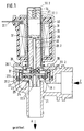
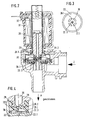
- the servo valve shown in FIGS. 1 and 2 has a valve housing 21 with an inlet Z and an outlet A.
- a differential piston 22 is movably arranged, which carries a valve plate 23 which is integrated into a rolling diaphragm 27, the outer edge of which 27.1 is connected to the valve housing 21, while its inner edge 27.2 is connected to the valve plate 23.
- the rolling diaphragm 27 separates the pressure chamber 25, which is connected to the valve inlet Z, from the control chamber 26, which is connected to the valve outlet A via the relief bore 22.1 and to the pressure chamber 25 via the control bore 22.2.
- the pressure chamber 25 is connected to the outlet A via the valve seat 24 when the valve is open.
- control chamber 26 contains a spring element 38 which has a straight section 38.1 which is guided through the control bore 22.2.
- a magnet system for controlling the valve is arranged with a magnet coil 31, which has electrical connections 31.1 and in which a guide tube 30 is arranged, the extended end 30.1 of the control chamber 26 above and on the sides limited.
- the guide tube 30 On its upper side, the guide tube 30 has a fixed end wall 30.2.
- Both the magnet armature 28 and the head piece 32 are arranged axially displaceably in the guide tube 30.
- the head piece 32 has on the side facing away from the magnet armature 28 an axial bore 32.1, in which a helical spring 34 acting as a return spring is arranged, which is supported with its outer end on the end wall 30.2.
- the head piece 32 On the side facing the magnet armature 28, the head piece 32 is supported on the magnet armature seal 28.1 by means of a rod-shaped spacer 35 which is guided through a longitudinal central bore 28.2 of the magnet armature 28. 2 and 4, the magnet armature seal 28.1 is integrated in an elastic membrane 29.2, which is arranged in the interior of a tubular holding element 29.
- the holding element 29 is fastened to the armature 28 by its end, while the other end 29.1 is opposite a support collar 36, which is arranged coaxially to the relief bore 22.1 on the surface of the differential piston 22.
- the support collar 36 as can be seen in FIG.
- the holding element 29 with the membrane 29.2 and the magnet armature seal 28.1 consists of a material, that has the best possible recovery properties, for example made of a silicone material.
- the arrangement of the membrane 29.2 within the holding element 29 is selected at such a distance from the lower end 29.1 and the elasticity of the membrane 29.2 is set such that when the armature 28 is in contact with the head piece 32, the magnet armature seal 28.1 on the underside of the holding element 29 is pressed out and on can open the opening of the relief bore 22.1.
- the length of the spacer 35 is dimensioned such that in the de-energized state of the magnet coil 31, the distance between the mutually facing surfaces of the magnet armature 28 and the head piece 32 corresponds at least to the path of the magnet armature seal 28.1 necessary for closing the relief bore 22.1.
- a short-circuit ring 37 can be arranged in the surface of the head piece 32 facing the magnet armature 28.
- the magnet coil 31 is surrounded by a magnet yoke 33.
- the head piece 32 and the magnet armature 28 are held at a predetermined distance by the action of the elastic membrane 29.2 via the spacer 35.
- the lower edge 29.1 of the mounting element 29 is seated on the support collar 36 and when the membrane 29.2 is relaxed and the magnet armature seal 28.1 is raised accordingly, the relief bore 22.1 is open and thus the valve under the action of the medium pressure in the open position.
- Appropriate training and prestressing of the roller membrane 27 can ensure this that the servo valve is open even at medium pressure 0.
Landscapes
- Engineering & Computer Science (AREA)
- General Engineering & Computer Science (AREA)
- Mechanical Engineering (AREA)
- Magnetically Actuated Valves (AREA)
- Valve Device For Special Equipments (AREA)
- Servomotors (AREA)
Claims (9)
- Servo-soupape commandée par son propre fluide, piloté par un induit magnétique, laquelle comporte, mobile dans une cage (21) de soupape, un piston différentiel (22) supportant la tête (23) de soupape et sur un côté duquel est disposée une chambre de compression (25) reliée à l'admission (Z) de la soupape, ladite chambre de compression étant reliée par un siège (24) opposé à la tête (23) à l'échappement (A) de la soupape, et sur l'autre côté dudit piston (22) étant disposée une chambre de régulation, laquelle est reliée à l'échappement (A) à travers un alésage de délestage (22.1) disposé centralement dans ledit piston (22) et à la chambre de compression (25) à travers un alésage de régulation (22.2) disposé de manière décentrée dans ledit piston, tandis que sur ladite soupape, l'induit magnétique (28) disposé coaxialement par rapport au piston (22), et passant dans une bobine magnétique (11.31), présente sur son extrémité pénétrant dans la chambre de régulation (26) un joint pour induit magnétique (28.1) placé en face de l'alésage de délestage, l'autre extrémité dudit induit magnétique étant située en face d'une pièce sommitale (32) disposée coaxialement à l'induit magnétique et au moins partiellement à l'intérieur de la bobine magnétique, ladite pièce sommitale (32) étant coulissable en direction axiale et s'appuyant sur son côté orienté vers l'induit (28) sur une pièce d'écartement (35), laquelle peut coulisser par rapport à l'induit magnétique de telle sorte que son extrémité opposée à ladite pièce sommitale (32) s'appuie sur un composant mobile (28.1) de la soupape de telle sorte qu'à l'état désexcité de la bobine, en raison d'une force élastique (29.2) agissant entre l'induit (28) et la pièce sommitale (32), s'établit une distance prédéterminée entre ledit induit magnétique (20) et ladite pièce sommitale (32), alors qu'à l'état excité de ladite bobine (31), l'induit (28) de la pièce sommitale (32) viennent s'appliquer l'un sur l'autre en s'opposant à l'effet de cette force élastique, caractérisée en ce que, pour une servo-soupape se fermant à l'état excité de la bobine (31), la pièce d'écartement (35) passe à travers un alésage longitudinal central (28.2) de l'induit (28) et s'appuie sur le côté du joint (28.1) opposé à l'alésage (22.1), ledit joint étant relié à l'induit (28) à la manière d'un composant mobile par un élément élastique (29.2) de telle sorte que, lorsque la bobine (31) est excitée, ledit joint (28.1) est serré sur l'alésage (22.1) en s'opposant à la force exercée par l'élément élastique (29.2) en raison du mouvement réciproque entre l'induit (28) et la pièce sommitale (32), la longueur de la pièce d'écartement (35) étant dimensionnée de telle sorte qu'à l'état désexcité de la bobine (31) la distance entre les faces mutuellement opposées de l'induit (28) et de la pièce sommitale (32) correspond au moins au trajet du joint (28) nécessaire pour la fermeture de l'alésage de délestage.
- Servo-soupape selon la revendication 1, caractérisée en ce que l'élément élastique est une membrane (29.2) dans laquelle est intégré le joint (28.1) de l'induit magnétique et dont le bord extérieur est relié au bord extérieur de la face de l'induit (28) orientée vers le piston différentiel (22).
- Servo-soupape selon la revendication 2, caractérisée en ce que la membrane (29.2) est disposée à l'intérieur d'un élément support (29) de forme tubulaire disposé coaxialement par rapport à l'induit magnétique (28) et dont une extrémité est reliée à cet induit magnétique (28) tandis que son autre extrémité fait face au piston différentiel (22), la distance entre la membrane (29.2) et cette extrémité étant telle, qu'à l'état désexcité de la bobine (31), l'induit (28) s'appuie, à travers l'élément support (29), sur ledit piston différentiel, ce qui a pour effet d'assurer la présence d'une distance prédéterminée entre le joint (28.1) et l'alésage (22.1).
- Servo-soupape selon la revendication 3, caractérisée en ce que le piston différentiel (22) présente, dans une zone opposée à l'extrémité de l'élément support (29), un collier de renfort de forme annulaire (36) lequel est muni d'au moins un trou radial (36.1) et au centre duquel est disposé le trou de l'alésage (22.1) sur la point d'un embout cunéiforme (22.3), la hauteur du collier (36) correspondant sensiblement à la hauteur de cet embout cunéiforme (22.3).
- Servo-soupape selon la revendication 3 ou 4, caractérisée en ce que l'élément du support (29), la membrane (29.2) et le joint (28.1) de l'induit sont constitués en une seule pièce en un matériau à base de silicone.
- Servo-soupape selon l'une des revendications 1 à 5, caractérisée en ce que, sur son côté opposé à l'induit magnétique (28), la pièce sommitale (32) s'appuie, à travers un ressort de rappel (34), sur une butée (30.2) reliée de manière fixe à la cage.
- Servo-soupape selon l'une des revendications 1 à 6, caractérisée en ce que l'induit (8.28) et la pièce sommitale (32) passent à l'intérieur d'un tube de guidage (36) à paroi fine, traversant la bobine (31) et relié de manière fixe à la cage (21).
- Servo-soupape selon la revendication 7, caractérisée en ce que le tube de guidage présente, sur son côté orienté vers le piston différentiel (22), un élargissement (20.1) entourant partiellement la chambre de régulation (26).
- Servo-soupape selon l'une des revendications 1 à 8, caractérisée en ce que dans la face de la pièce sommitale (22) orientée vers l'induit magnétique (28) est disposée une bague court-circuitée (37).
Applications Claiming Priority (2)
| Application Number | Priority Date | Filing Date | Title |
|---|---|---|---|
| DE4038736 | 1990-12-05 | ||
| DE4038736A DE4038736A1 (de) | 1990-12-05 | 1990-12-05 | Eigenmediumbetaetigtes, durch einen magnetanker gesteuertes servoventil |
Publications (2)
| Publication Number | Publication Date |
|---|---|
| EP0489331A1 EP0489331A1 (fr) | 1992-06-10 |
| EP0489331B1 true EP0489331B1 (fr) | 1995-05-10 |
Family
ID=6419615
Family Applications (1)
| Application Number | Title | Priority Date | Filing Date |
|---|---|---|---|
| EP91120095A Expired - Lifetime EP0489331B1 (fr) | 1990-12-05 | 1991-11-26 | Soupape actionnée par son propre fluide et commandée par un électro-aimant |
Country Status (4)
| Country | Link |
|---|---|
| EP (1) | EP0489331B1 (fr) |
| AT (1) | ATE122444T1 (fr) |
| DE (2) | DE4038736A1 (fr) |
| DK (1) | DK0489331T3 (fr) |
Cited By (3)
| Publication number | Priority date | Publication date | Assignee | Title |
|---|---|---|---|---|
| DE202006001009U1 (de) * | 2006-01-24 | 2007-06-06 | A. u. K. Müller GmbH & Co KG | Eigenmediumbetätigtes durch einen Magnetanker gesteuertes Servoventil |
| DE102009045773A1 (de) * | 2009-10-16 | 2011-04-21 | Prominent Dosiertechnik Gmbh | Druckhalteventil |
| EP4663989A1 (fr) * | 2024-06-13 | 2025-12-17 | Neoperl GmbH | Vanne sanitaire avec soupape pilote |
Families Citing this family (6)
| Publication number | Priority date | Publication date | Assignee | Title |
|---|---|---|---|---|
| DE4438065A1 (de) * | 1994-10-25 | 1996-05-02 | Rexroth Mannesmann Gmbh | Vorgesteuertes 2/2-Wege-Sitzventil |
| EP1416207A1 (fr) * | 2002-10-30 | 2004-05-06 | Rpe S.R.L. | Soupape à membrane avec une soupape pilote |
| ITMI20130403U1 (it) | 2013-11-19 | 2015-05-20 | Rpe Srl | Valvola, in particolare valvola di scarico di acqua per servizi igienici |
| US11788644B2 (en) | 2014-12-03 | 2023-10-17 | Hydralectric Group Ltd | Proportional valve, electric shower incorporating the proportional valve and tap incorporating same |
| EP4112984A1 (fr) | 2021-06-30 | 2023-01-04 | Danfoss A/S | Soupape à solénoïde commandée par pilote |
| CN114542328B (zh) * | 2022-03-03 | 2024-01-09 | 北京星河动力航天科技股份有限公司 | 组合阀、火箭发动机及运载火箭 |
Family Cites Families (3)
| Publication number | Priority date | Publication date | Assignee | Title |
|---|---|---|---|---|
| FR1280661A (fr) * | 1960-11-18 | 1962-01-08 | Neypric Ets | Clapet à commande électro-magnétique |
| BE694157A (fr) * | 1966-05-14 | 1967-07-31 | ||
| DE2439271A1 (de) * | 1974-08-16 | 1976-03-11 | Herion Werke Kg | Durchgangsmagnetventil |
-
1990
- 1990-12-05 DE DE4038736A patent/DE4038736A1/de not_active Withdrawn
-
1991
- 1991-11-26 EP EP91120095A patent/EP0489331B1/fr not_active Expired - Lifetime
- 1991-11-26 DK DK91120095.4T patent/DK0489331T3/da active
- 1991-11-26 DE DE59105441T patent/DE59105441D1/de not_active Expired - Fee Related
- 1991-11-26 AT AT91120095T patent/ATE122444T1/de not_active IP Right Cessation
Cited By (3)
| Publication number | Priority date | Publication date | Assignee | Title |
|---|---|---|---|---|
| DE202006001009U1 (de) * | 2006-01-24 | 2007-06-06 | A. u. K. Müller GmbH & Co KG | Eigenmediumbetätigtes durch einen Magnetanker gesteuertes Servoventil |
| DE102009045773A1 (de) * | 2009-10-16 | 2011-04-21 | Prominent Dosiertechnik Gmbh | Druckhalteventil |
| EP4663989A1 (fr) * | 2024-06-13 | 2025-12-17 | Neoperl GmbH | Vanne sanitaire avec soupape pilote |
Also Published As
| Publication number | Publication date |
|---|---|
| DE59105441D1 (de) | 1995-06-14 |
| DE4038736A1 (de) | 1992-06-11 |
| DK0489331T3 (da) | 1995-09-04 |
| ATE122444T1 (de) | 1995-05-15 |
| EP0489331A1 (fr) | 1992-06-10 |
Similar Documents
| Publication | Publication Date | Title |
|---|---|---|
| EP0578168B1 (fr) | Valve | |
| DE19826076C1 (de) | Doppelsicherheitsventil | |
| EP3263962B1 (fr) | Soupape | |
| DE4439890C2 (de) | Ventilanordnung | |
| DE3410795C2 (de) | elektropneumatischer Wandler | |
| DE3823430C3 (de) | Hydraulischer Teleskopstoßdämpfer | |
| DE4208886A1 (de) | Daempfkraftveraenderbarer schwingungsdaempfer mit notbetriebseinstellung | |
| EP1004066A1 (fr) | Soupape hydraulique electromagnetique | |
| DE2757803A1 (de) | Magnetventil | |
| EP3039324B1 (fr) | Ensemble soupape | |
| DE10040763A1 (de) | Elektromagnetisch betätigtes Ventil, insbesondere für hydraulische Bremsanlagen in Kraftfahrzeugen | |
| WO1999064769A2 (fr) | Double vanne de securite | |
| EP0489331B1 (fr) | Soupape actionnée par son propre fluide et commandée par un électro-aimant | |
| WO2005066531A1 (fr) | Soupape electromagnetique, destinee notamment a un systeme de freinage d'un vehicule automobile | |
| EP0416339A1 (fr) | Servo-soupape commandée par une armature activée par un propre moyen | |
| DE3439378C2 (fr) | ||
| DE3780642T2 (de) | Elektromagnetisches ventil. | |
| DE2855902A1 (de) | Elektromagnetisch betaetigbares 3/2-wegeventil, insbesondere zur fernsteuerung von einseitig mit einem fluid beaufschlagbaren vorrichtungen | |
| DE4201450C1 (fr) | ||
| DE2657197A1 (de) | Elektromagnetische ventileinrichtung | |
| DE10216485B4 (de) | Verfahren zur Einstellung eines Elektromagnetventils | |
| DE3705514C2 (fr) | ||
| EP3844374A1 (fr) | Soupape | |
| WO1998033687A1 (fr) | Vanne de regulation a plusieurs voies | |
| EP3643954A1 (fr) | Soupape électromagnétique, procédé de fonctionnement d'une soupape électromagnétique |
Legal Events
| Date | Code | Title | Description |
|---|---|---|---|
| PUAI | Public reference made under article 153(3) epc to a published international application that has entered the european phase |
Free format text: ORIGINAL CODE: 0009012 |
|
| AK | Designated contracting states |
Kind code of ref document: A1 Designated state(s): AT BE CH DE DK FR GB IT LI NL |
|
| 17P | Request for examination filed |
Effective date: 19921125 |
|
| 17Q | First examination report despatched |
Effective date: 19940225 |
|
| GRAA | (expected) grant |
Free format text: ORIGINAL CODE: 0009210 |
|
| ITF | It: translation for a ep patent filed | ||
| AK | Designated contracting states |
Kind code of ref document: B1 Designated state(s): AT BE CH DE DK FR GB IT LI NL |
|
| PG25 | Lapsed in a contracting state [announced via postgrant information from national office to epo] |
Ref country code: GB Effective date: 19950510 Ref country code: BE Effective date: 19950510 |
|
| REF | Corresponds to: |
Ref document number: 122444 Country of ref document: AT Date of ref document: 19950515 Kind code of ref document: T |
|
| REF | Corresponds to: |
Ref document number: 59105441 Country of ref document: DE Date of ref document: 19950614 |
|
| ET | Fr: translation filed | ||
| REG | Reference to a national code |
Ref country code: DK Ref legal event code: T3 |
|
| GBV | Gb: ep patent (uk) treated as always having been void in accordance with gb section 77(7)/1977 [no translation filed] |
Effective date: 19950510 |
|
| PG25 | Lapsed in a contracting state [announced via postgrant information from national office to epo] |
Ref country code: AT Effective date: 19951126 |
|
| PG25 | Lapsed in a contracting state [announced via postgrant information from national office to epo] |
Ref country code: LI Effective date: 19951130 Ref country code: CH Effective date: 19951130 |
|
| PLBE | No opposition filed within time limit |
Free format text: ORIGINAL CODE: 0009261 |
|
| STAA | Information on the status of an ep patent application or granted ep patent |
Free format text: STATUS: NO OPPOSITION FILED WITHIN TIME LIMIT |
|
| 26N | No opposition filed | ||
| PG25 | Lapsed in a contracting state [announced via postgrant information from national office to epo] |
Ref country code: NL Effective date: 19960601 |
|
| REG | Reference to a national code |
Ref country code: CH Ref legal event code: PL |
|
| NLV4 | Nl: lapsed or anulled due to non-payment of the annual fee |
Effective date: 19960601 |
|
| PGFP | Annual fee paid to national office [announced via postgrant information from national office to epo] |
Ref country code: FR Payment date: 19991029 Year of fee payment: 9 |
|
| PGFP | Annual fee paid to national office [announced via postgrant information from national office to epo] |
Ref country code: DK Payment date: 19991126 Year of fee payment: 9 |
|
| PGFP | Annual fee paid to national office [announced via postgrant information from national office to epo] |
Ref country code: DE Payment date: 19991210 Year of fee payment: 9 |
|
| PG25 | Lapsed in a contracting state [announced via postgrant information from national office to epo] |
Ref country code: DK Free format text: LAPSE BECAUSE OF NON-PAYMENT OF DUE FEES Effective date: 20001126 |
|
| REG | Reference to a national code |
Ref country code: DK Ref legal event code: EBP |
|
| PG25 | Lapsed in a contracting state [announced via postgrant information from national office to epo] |
Ref country code: FR Free format text: LAPSE BECAUSE OF NON-PAYMENT OF DUE FEES Effective date: 20010731 |
|
| PG25 | Lapsed in a contracting state [announced via postgrant information from national office to epo] |
Ref country code: DE Free format text: LAPSE BECAUSE OF NON-PAYMENT OF DUE FEES Effective date: 20010801 |
|
| REG | Reference to a national code |
Ref country code: FR Ref legal event code: ST |
|
| PG25 | Lapsed in a contracting state [announced via postgrant information from national office to epo] |
Ref country code: IT Free format text: LAPSE BECAUSE OF NON-PAYMENT OF DUE FEES;WARNING: LAPSES OF ITALIAN PATENTS WITH EFFECTIVE DATE BEFORE 2007 MAY HAVE OCCURRED AT ANY TIME BEFORE 2007. THE CORRECT EFFECTIVE DATE MAY BE DIFFERENT FROM THE ONE RECORDED. Effective date: 20051126 |