EP0489344A1 - Verfahren zur Identifikation einer gedrückten Taste einer Tastatur - Google Patents
Verfahren zur Identifikation einer gedrückten Taste einer Tastatur Download PDFInfo
- Publication number
- EP0489344A1 EP0489344A1 EP91120226A EP91120226A EP0489344A1 EP 0489344 A1 EP0489344 A1 EP 0489344A1 EP 91120226 A EP91120226 A EP 91120226A EP 91120226 A EP91120226 A EP 91120226A EP 0489344 A1 EP0489344 A1 EP 0489344A1
- Authority
- EP
- European Patent Office
- Prior art keywords
- sensors
- plate
- signals
- keyboard
- terminals
- Prior art date
- Legal status (The legal status is an assumption and is not a legal conclusion. Google has not performed a legal analysis and makes no representation as to the accuracy of the status listed.)
- Withdrawn
Links
- 238000000034 method Methods 0.000 title claims description 12
- 230000007423 decrease Effects 0.000 claims abstract description 6
- 238000005034 decoration Methods 0.000 claims description 7
- 239000000463 material Substances 0.000 claims description 5
- 230000005540 biological transmission Effects 0.000 claims description 4
- 230000004913 activation Effects 0.000 claims description 3
- 238000012790 confirmation Methods 0.000 claims description 3
- 210000001520 comb Anatomy 0.000 description 5
- 239000004065 semiconductor Substances 0.000 description 4
- 230000004048 modification Effects 0.000 description 3
- 238000012986 modification Methods 0.000 description 3
- 230000008569 process Effects 0.000 description 3
- 230000008859 change Effects 0.000 description 2
- 239000011159 matrix material Substances 0.000 description 2
- TVEXGJYMHHTVKP-UHFFFAOYSA-N 6-oxabicyclo[3.2.1]oct-3-en-7-one Chemical compound C1C2C(=O)OC1C=CC2 TVEXGJYMHHTVKP-UHFFFAOYSA-N 0.000 description 1
- 239000000853 adhesive Substances 0.000 description 1
- 230000001070 adhesive effect Effects 0.000 description 1
- 230000008901 benefit Effects 0.000 description 1
- 239000013043 chemical agent Substances 0.000 description 1
- 239000013078 crystal Substances 0.000 description 1
- 238000013461 design Methods 0.000 description 1
- 239000000428 dust Substances 0.000 description 1
- 230000000694 effects Effects 0.000 description 1
- 239000011521 glass Substances 0.000 description 1
- 239000003292 glue Substances 0.000 description 1
- 238000003780 insertion Methods 0.000 description 1
- 230000037431 insertion Effects 0.000 description 1
- 238000009434 installation Methods 0.000 description 1
- 230000001788 irregular Effects 0.000 description 1
- 229910052751 metal Inorganic materials 0.000 description 1
- 239000002184 metal Substances 0.000 description 1
- CWQXQMHSOZUFJS-UHFFFAOYSA-N molybdenum disulfide Chemical compound S=[Mo]=S CWQXQMHSOZUFJS-UHFFFAOYSA-N 0.000 description 1
- 239000002245 particle Substances 0.000 description 1
- 230000010363 phase shift Effects 0.000 description 1
- 230000001681 protective effect Effects 0.000 description 1
- 239000011347 resin Substances 0.000 description 1
- 229920005989 resin Polymers 0.000 description 1
- 238000007650 screen-printing Methods 0.000 description 1
- 230000035945 sensitivity Effects 0.000 description 1
- 229920002994 synthetic fiber Polymers 0.000 description 1
- XLYOFNOQVPJJNP-UHFFFAOYSA-N water Substances O XLYOFNOQVPJJNP-UHFFFAOYSA-N 0.000 description 1
Images


Classifications
-
- H—ELECTRICITY
- H01—ELECTRIC ELEMENTS
- H01H—ELECTRIC SWITCHES; RELAYS; SELECTORS; EMERGENCY PROTECTIVE DEVICES
- H01H13/00—Switches having rectilinearly-movable operating part or parts adapted for pushing or pulling in one direction only, e.g. push-button switch
- H01H13/70—Switches having rectilinearly-movable operating part or parts adapted for pushing or pulling in one direction only, e.g. push-button switch having a plurality of operating members associated with different sets of contacts, e.g. keyboard
- H01H13/78—Switches having rectilinearly-movable operating part or parts adapted for pushing or pulling in one direction only, e.g. push-button switch having a plurality of operating members associated with different sets of contacts, e.g. keyboard characterised by the contacts or the contact sites
- H01H13/785—Switches having rectilinearly-movable operating part or parts adapted for pushing or pulling in one direction only, e.g. push-button switch having a plurality of operating members associated with different sets of contacts, e.g. keyboard characterised by the contacts or the contact sites characterised by the material of the contacts, e.g. conductive polymers
-
- H—ELECTRICITY
- H01—ELECTRIC ELEMENTS
- H01H—ELECTRIC SWITCHES; RELAYS; SELECTORS; EMERGENCY PROTECTIVE DEVICES
- H01H13/00—Switches having rectilinearly-movable operating part or parts adapted for pushing or pulling in one direction only, e.g. push-button switch
- H01H13/70—Switches having rectilinearly-movable operating part or parts adapted for pushing or pulling in one direction only, e.g. push-button switch having a plurality of operating members associated with different sets of contacts, e.g. keyboard
- H01H13/702—Switches having rectilinearly-movable operating part or parts adapted for pushing or pulling in one direction only, e.g. push-button switch having a plurality of operating members associated with different sets of contacts, e.g. keyboard with contacts carried by or formed from layers in a multilayer structure, e.g. membrane switches
-
- H—ELECTRICITY
- H03—ELECTRONIC CIRCUITRY
- H03K—PULSE TECHNIQUE
- H03K17/00—Electronic switching or gating, i.e. not by contact-making and –breaking
- H03K17/94—Electronic switching or gating, i.e. not by contact-making and –breaking characterised by the way in which the control signals are generated
- H03K17/96—Touch switches
- H03K17/9618—Touch switches using a plurality of detectors, e.g. keyboard
-
- H—ELECTRICITY
- H03—ELECTRONIC CIRCUITRY
- H03K—PULSE TECHNIQUE
- H03K17/00—Electronic switching or gating, i.e. not by contact-making and –breaking
- H03K17/94—Electronic switching or gating, i.e. not by contact-making and –breaking characterised by the way in which the control signals are generated
- H03K17/96—Touch switches
- H03K17/9625—Touch switches using a force resistance transducer
-
- H—ELECTRICITY
- H03—ELECTRONIC CIRCUITRY
- H03M—CODING; DECODING; CODE CONVERSION IN GENERAL
- H03M11/00—Coding in connection with keyboards or like devices, i.e. coding of the position of operated keys
- H03M11/22—Static coding
-
- H—ELECTRICITY
- H01—ELECTRIC ELEMENTS
- H01H—ELECTRIC SWITCHES; RELAYS; SELECTORS; EMERGENCY PROTECTIVE DEVICES
- H01H2201/00—Contacts
- H01H2201/022—Material
- H01H2201/032—Conductive polymer; Rubber
- H01H2201/036—Variable resistance
-
- H—ELECTRICITY
- H01—ELECTRIC ELEMENTS
- H01H—ELECTRIC SWITCHES; RELAYS; SELECTORS; EMERGENCY PROTECTIVE DEVICES
- H01H2219/00—Legends
- H01H2219/002—Legends replaceable; adaptable
-
- H—ELECTRICITY
- H01—ELECTRIC ELEMENTS
- H01H—ELECTRIC SWITCHES; RELAYS; SELECTORS; EMERGENCY PROTECTIVE DEVICES
- H01H2227/00—Dimensions; Characteristics
- H01H2227/002—Layer thickness
- H01H2227/004—Membrane
-
- H—ELECTRICITY
- H01—ELECTRIC ELEMENTS
- H01H—ELECTRIC SWITCHES; RELAYS; SELECTORS; EMERGENCY PROTECTIVE DEVICES
- H01H2231/00—Applications
- H01H2231/034—Coordinate determination
-
- H—ELECTRICITY
- H01—ELECTRIC ELEMENTS
- H01H—ELECTRIC SWITCHES; RELAYS; SELECTORS; EMERGENCY PROTECTIVE DEVICES
- H01H2239/00—Miscellaneous
- H01H2239/038—Anti-vandalism
Definitions
- the present invention relates to a keypad for a control panel comprising a base plate, a decor plate provided with identification markings of keys to which very specific functions are assigned, as well as sensors sensitive to an activation pressure arranged below each key between the base plate and the decor plate.
- the invention also relates to a method for identifying an activated key of a keyboard consisting of a grid of m lines and n columns of keys of such a keyboard.
- the invention relates in particular to keyboards for control panels intended to trigger and supervise operations and operations of all kinds of machines, apparatus, installations, etc.
- a keyboard of this kind is, for example, known from patent application EP-0 210 386 which proposes a control panel, of laminated structure, comprising a hard sheet or plate forming a support with a covering layer between which is disposed in sandwich a crystal which reacts to an external pressure by the emission or modification of an electrical signal.
- EP-0 366 832 proposes a cover for a keyboard with keys of a control panel which is in the form of a rigid plate which can be deposited on the operating surface of the keyboard and which has in the corresponding places at the keyboard keys at least one pressure transmission zone which is flexible or of reduced rigidity.
- keyboards have certain disadvantages, depending on their type of application.
- these keyboards with keys or control panels are sensitive to external mechanical influences and can be easily damaged due to blows or ill-treatment.
- the known keyboards are relatively sensitive to external vibrations.
- Such a sensor essentially consists of a thin semiconductor film which can be formed by tiny particles, for example of molybdenum disulphide with a size of the order of 1 to 10 microns embedded in a support resin.
- Such a film has a certain surface resistance which, when the film is applied against a conductive surface can be reduced as a result of an increase in the number of points of contact with this conductive surface under the effect of localized pressure.
- An advantageous embodiment consists in associating such an FSR film with a film on which a conductive network is deposited in the form of two combs of electrodes in interdigital arrangement. These two films are sealed to each other so that the electrode combs touch the surface of the FSR semiconductor layer.
- the resistance between the terminals of the electrode combs is very high, generally of the order of several megaohms.
- the FSR is subjected to a force perpendicular to its surface, the resistance decreases approximately exponentially.
- keyboards could be exploited in a keyboard by providing, instead of the usual electromechanical sensors of the FSR type sensors, all the more since, given the great sensitivity of this type of sensor, it could react to a local pressure. applied through a more or less rigid protective plate which would be provided on the outside, identification markings of the keys.
- keyboards whose keys would be associated with FSR force sensors could not be produced so far due to problems in identifying the activated keys. Indeed, by using a keyboard comprising a grid or matrix of FSR sensors forming the keyboard keys, it would suffice, to know the key actuated by a finger or a stylus, to determine which of all the sensors whose resistance is the lowest .
- the object of the present invention is to provide a new keyboard with keys which has better resistance to external mechanical influences, as well as a method for identifying an activated key which is both precise and rapid.
- the present invention provides a keypad for control panels of the type described in the preamble which is characterized in that the sensors are force sensors with variable resistance of the FSR type and in that the decor plate is a semi-rigid plate.
- the structure can also include a layer of compressible material between the base plate and the decor plate.
- the force sensors are then inserted, below the keys or key zones, either between the decoration plate and the compressible layer, or between the latter and the base plate.
- the decoration plate may have a marking of great finesse, that is to say of short distance between the different keys, which allows a great power of resolution.
- the marking of the keys can be carried out in the form of strips without interruption or in another way. It is also possible to provide grooves below the decor plate allowing the insertion and removal of strips provided with the key markings which allows a rapid change of the markings and the identification of the keys.
- the keyboard decor plate according to the present invention is dust and water tight, and, as required, resistant to chemical agents and / or acts of vandalism. Given the properties of FSR sensors, the force required to activate the keys is adjustable.
- the decor plate can have a completely smooth surface and be made of glass metal or synthetic material according to a presentation and a design in accordance with the wishes of the user. Apart from a long lifespan, these decorative plates are characterized by a small thickness and the possibility of a possible combination with electrooptical elements.
- the sensors react by a variable resistance which decreases according to the force of activation of the keys.
- Each sensor comprises, in a manner known per se, a semiconductor film laminated to a film with two combs of electrodes. When pressure is applied to such a sensor, the semiconductor layer more or less shunts the neighboring electrodes of the two combs and reduces the resistance between them.
- the invention also relates to a method for identifying an activated key of such a keyboard consisting of a grid of m rows and n columns of individual keys, each associated with a force sensor whose electrical resistance decreases in proportion to a force applied to its surface, in which the mxn sensors are sandwiched between a rigid support plate and a semi-rigid protection and decoration plate bearing the identification marks of the keys, characterized in that one simultaneously injects on the m terminals of the m lines of sensors m different electrical signals which can be dissociated from each other, in that the m signals are collected on the terminals of the n columns, in that the signal i whose among i is determined the degree of deformation exceeds a predetermined threshold and which corresponds to the line i in which the most activated sensor C ij is located, in that one injects simultaneously on the n terminals of the n columns of sensors n different and dissociable electrical signals between them, in that one collects on the terminals of the m lines the n signals as determined
- the deformations detected on the signals during the passage by the sensors can be the modification of their amplitude following the change of electrical resistance of the sensors. It is however also possible to detect other modifications such as phase shift or frequency, when the sensors are integrated in an oscillator circuit.
- Figure 1 schematically shows a section of a portion of a control panel in the form of a laminated structure and comprising a decor plate 1 provided with markings, pressure sensitive sensors 4, a compressible layer 2 and a base plate 3.
- the keys are represented by the reference 5. It is possible to provide on the underside of the decor plate one or more windows 7 into which removable strips 8 can be introduced in order to use different texts.
- the reference 9 symbolizes an adhesive between the different layers.
- FIG 2 shows schematically the same structure as that of Figure 1 with the difference that, unlike the embodiment according to Figure 1, the pressure sensitive sensors 4 are located between the compressible elastic layer 2 and the base plate 3.
- FIG. 3 illustrates the possibility of designing the upper surface of the base plate 3 in the form of a plate 6 in which the compressible layer 2 can be housed, the pressure sensors 4 being able to be located, either between the compressible layer 2 and the base plate 3, ie between the compressible layer 2 and the decor plate 1.
- FIG. 4 finally represents a compressible layer 2 provided with notches below the keys 5 of the decoration plate 1 and in which the sensors 4 and of the pressure transmission pads 10 are located. These pads 10 have convex upper and lower faces and allow better transmission of the pressure on the sensors 4.
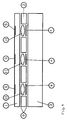
- FIG. 5 schematically represents a keyboard comprising a grid of sensors 10 of the FSR type sandwiched between two layers 16 and 18 of compressible material, taken, in turn, sandwiched between a rigid base plate 12 and a semi-plate - rigid decoration and protection 14.
- FIG. 6 schematically shows a network of 16 sensors 10 for a control keyboard according to FIG. 5. These 16 sensors are arranged according to a grid or matrix of 4 rows 1, 2, 3, 4 and 4 columns A, B, C, D.
- the first phase consists, for example, in locating first on which of the 4 lines of the grid in FIG. 6 the activated sensor has the most probability of being located.
- electrical identification signals are injected on each of the 4 lines 1 to 4. It therefore takes 4 signals which are represented in FIG. 7 and which are numbered 1 to 4. As this figure shows, these are simple signals with a period T, identical in their configuration, but phase shifted a quarter of the relative to each other. These signals are then collected at the 4 terminals of columns A, B, C, D which, for the needs of the cause can be connected together.
- FIG. 8 represents an example of a signal detected on the terminals A, B, C, D, this signal representing the sum weighted signals 1, 2, 3, 4.
- a threshold S of amplitude which will probably be exceeded by a signal of identification after passing it through an activated sensor.
- this threshold S Only the portion corresponding to signal 3 exceeds this threshold S. Since this portion comes from the signal injected in line 3, it must be concluded that it is in the 3rd line that the most active FSR sensor.
- the second phase consists in determining the column in which the most activated sensor is located. To this end, the procedure for determining the line as described above is carried out in a similar manner. We therefore inject 4 identification signals used in the 4 columns A, B, C, D. These signals are then collected on lines 1, 2, 3, 4, the terminals of which can be connected together for the needs of the cause. Assuming that we collect on the 4 lines the signal shown in Figure 19 we select the portion exceeding the amplitude threshold S. In this case it is the signal injected in column B, which means that the most active sensor is in column B of the grid.
- the key identification mode proposed by the present invention has, in addition to precision, the advantage of being faster than a punctual scan of each of the sensors. Indeed, assuming that we have a keyboard with a grid of m rows and n columns of sensors, it suffices to analyze m + n sensors to locate the most activated sensor while a punctual scan requires the analysis of mxn signals.
- the identification process can be repeated as confirmation.
Landscapes
- Engineering & Computer Science (AREA)
- Theoretical Computer Science (AREA)
- Input From Keyboards Or The Like (AREA)
- Push-Button Switches (AREA)
Applications Claiming Priority (4)
| Application Number | Priority Date | Filing Date | Title |
|---|---|---|---|
| DE9016410U | 1990-12-03 | ||
| DE9016410U DE9016410U1 (de) | 1990-12-03 | 1990-12-03 | Frontplatte mit Folientastatur |
| BE9100157A BE1004642A3 (fr) | 1991-02-18 | 1991-02-18 | Procede d'identification d'une touche activee d'un clavier. |
| BE9100157 | 1991-02-18 |
Publications (1)
| Publication Number | Publication Date |
|---|---|
| EP0489344A1 true EP0489344A1 (de) | 1992-06-10 |
Family
ID=25662571
Family Applications (1)
| Application Number | Title | Priority Date | Filing Date |
|---|---|---|---|
| EP91120226A Withdrawn EP0489344A1 (de) | 1990-12-03 | 1991-11-27 | Verfahren zur Identifikation einer gedrückten Taste einer Tastatur |
Country Status (1)
| Country | Link |
|---|---|
| EP (1) | EP0489344A1 (de) |
Cited By (13)
| Publication number | Priority date | Publication date | Assignee | Title |
|---|---|---|---|---|
| WO1994001935A1 (en) * | 1992-07-13 | 1994-01-20 | Interlink Electronics, Inc. | Adaptive keypad |
| AT397871B (de) * | 1992-03-02 | 1994-07-25 | Hoerbiger Fluidtechnik Gmbh | Wegmesseinrichtung |
| EP0617556A1 (de) * | 1993-03-22 | 1994-09-28 | SONY DEUTSCHLAND GmbH | Rundfunksignalempfänger |
| FR2707772A1 (fr) * | 1993-06-30 | 1995-01-20 | Fusilier Jean Marie | Clavier plat perfectionné à touches progressives rappelées pour la télécommande sans fil d'une unité fonctionnelle. |
| DE4339931C1 (de) * | 1993-11-24 | 1995-03-30 | Daimler Benz Ag | Positionsgeber, insbesondere für den Gangwählhebel eines Fahrzeuggetriebes |
| WO1996020533A1 (en) * | 1994-12-28 | 1996-07-04 | Screentec Ky | Keyboard |
| EP0901229A3 (de) * | 1997-09-04 | 1999-04-21 | Delco Electronics Europe GmbH | Betrieb einer elektrisch bedienbaren Vorrichtung |
| EP1422734A1 (de) * | 2002-11-25 | 2004-05-26 | IEE INTERNATIONAL ELECTRONICS & ENGINEERING S.A. | Dateneingangsverfahren |
| WO2004049364A1 (fr) * | 2002-11-25 | 2004-06-10 | Iee International Electronics & Engineering S.A. | Dispositif d'entree de donnees |
| GB2453911A (en) * | 2007-03-26 | 2009-04-29 | Nokia Corp | An input pad having an array of resistive sensing pads disposed under a top surface layer |
| WO2012175369A1 (fr) * | 2011-06-23 | 2012-12-27 | Delphi Technologies, Inc. | Panneau de commande comportant une touche retro-eclairee de type resistive |
| EP2689532B1 (de) * | 2011-03-21 | 2015-01-21 | Delphi Technologies, Inc. | Bedienfeld mit resistiven schaltflächen und abstandhaltern |
| CN105518586A (zh) * | 2014-08-26 | 2016-04-20 | 深圳纽迪瑞科技开发有限公司 | 分立式压力感应器和电子设备 |
Citations (7)
| Publication number | Priority date | Publication date | Assignee | Title |
|---|---|---|---|---|
| GB2047448A (en) * | 1979-04-16 | 1980-11-26 | Singer Co | Input switch arrangement |
| GB2064873A (en) * | 1979-11-26 | 1981-06-17 | Eventoff Franklin Neal | Pressure sensitive electric switch |
| GB2077508A (en) * | 1980-05-09 | 1981-12-16 | Weatherley Richard | Variable resistance pressure- sensitive laminate |
| US4481815A (en) * | 1982-12-23 | 1984-11-13 | Overton Kenneth J | Tactile sensor |
| GB2163602A (en) * | 1984-08-07 | 1986-02-26 | Casio Computer Co Ltd | Key switch structure |
| GB2191340A (en) * | 1986-05-20 | 1987-12-09 | Amalgamated Wireless Australas | Interchangeable designation for membrane keyboard |
| EP0259894A2 (de) * | 1986-09-12 | 1988-03-16 | Wacom Company, Ltd. | Lagebestimmungsgerät |
-
1991
- 1991-11-27 EP EP91120226A patent/EP0489344A1/de not_active Withdrawn
Patent Citations (7)
| Publication number | Priority date | Publication date | Assignee | Title |
|---|---|---|---|---|
| GB2047448A (en) * | 1979-04-16 | 1980-11-26 | Singer Co | Input switch arrangement |
| GB2064873A (en) * | 1979-11-26 | 1981-06-17 | Eventoff Franklin Neal | Pressure sensitive electric switch |
| GB2077508A (en) * | 1980-05-09 | 1981-12-16 | Weatherley Richard | Variable resistance pressure- sensitive laminate |
| US4481815A (en) * | 1982-12-23 | 1984-11-13 | Overton Kenneth J | Tactile sensor |
| GB2163602A (en) * | 1984-08-07 | 1986-02-26 | Casio Computer Co Ltd | Key switch structure |
| GB2191340A (en) * | 1986-05-20 | 1987-12-09 | Amalgamated Wireless Australas | Interchangeable designation for membrane keyboard |
| EP0259894A2 (de) * | 1986-09-12 | 1988-03-16 | Wacom Company, Ltd. | Lagebestimmungsgerät |
Non-Patent Citations (1)
| Title |
|---|
| MEASUREMENT + CONTROL vol. 18, no. 7, Septembre 1985, LONDRES GB pages 262 - 265; ROBERTSON ET AL: 'tactile sensor system for robotics' * |
Cited By (24)
| Publication number | Priority date | Publication date | Assignee | Title |
|---|---|---|---|---|
| AT397871B (de) * | 1992-03-02 | 1994-07-25 | Hoerbiger Fluidtechnik Gmbh | Wegmesseinrichtung |
| WO1994001935A1 (en) * | 1992-07-13 | 1994-01-20 | Interlink Electronics, Inc. | Adaptive keypad |
| US5510783A (en) * | 1992-07-13 | 1996-04-23 | Interlink Electronics, Inc. | Adaptive keypad |
| EP0617556A1 (de) * | 1993-03-22 | 1994-09-28 | SONY DEUTSCHLAND GmbH | Rundfunksignalempfänger |
| US5532753A (en) * | 1993-03-22 | 1996-07-02 | Sony Deutschland Gmbh | Remote-controlled on-screen audio/video receiver control apparatus |
| FR2707772A1 (fr) * | 1993-06-30 | 1995-01-20 | Fusilier Jean Marie | Clavier plat perfectionné à touches progressives rappelées pour la télécommande sans fil d'une unité fonctionnelle. |
| DE4339931C1 (de) * | 1993-11-24 | 1995-03-30 | Daimler Benz Ag | Positionsgeber, insbesondere für den Gangwählhebel eines Fahrzeuggetriebes |
| WO1996020533A1 (en) * | 1994-12-28 | 1996-07-04 | Screentec Ky | Keyboard |
| US5917437A (en) * | 1994-12-28 | 1999-06-29 | Screentec Ky | Keyboard |
| EP0901229A3 (de) * | 1997-09-04 | 1999-04-21 | Delco Electronics Europe GmbH | Betrieb einer elektrisch bedienbaren Vorrichtung |
| CN100367427C (zh) * | 2002-11-25 | 2008-02-06 | Iee国际电子及工程股份有限公司 | 数据输入设备 |
| WO2004049364A1 (fr) * | 2002-11-25 | 2004-06-10 | Iee International Electronics & Engineering S.A. | Dispositif d'entree de donnees |
| EP1422734A1 (de) * | 2002-11-25 | 2004-05-26 | IEE INTERNATIONAL ELECTRONICS & ENGINEERING S.A. | Dateneingangsverfahren |
| US7800586B2 (en) | 2002-11-25 | 2010-09-21 | IEE International Elecronics & Engineering S.A. | Data input device |
| GB2453911A (en) * | 2007-03-26 | 2009-04-29 | Nokia Corp | An input pad having an array of resistive sensing pads disposed under a top surface layer |
| EP2689532B1 (de) * | 2011-03-21 | 2015-01-21 | Delphi Technologies, Inc. | Bedienfeld mit resistiven schaltflächen und abstandhaltern |
| CN103619637A (zh) * | 2011-06-23 | 2014-03-05 | 德尔菲技术公司 | 包括电阻类型背光键的控制面板 |
| FR2976867A1 (fr) * | 2011-06-23 | 2012-12-28 | Delphi Tech Inc | Panneau de commande comportant une touche retro-eclairee de type resistive |
| US8926107B2 (en) | 2011-06-23 | 2015-01-06 | Delphi Technologies, Inc. | Control panel including a resistive-type backlit key |
| WO2012175369A1 (fr) * | 2011-06-23 | 2012-12-27 | Delphi Technologies, Inc. | Panneau de commande comportant une touche retro-eclairee de type resistive |
| CN103619637B (zh) * | 2011-06-23 | 2016-10-12 | 德尔菲技术公司 | 包括电阻类型背光键的控制面板 |
| CN105518586A (zh) * | 2014-08-26 | 2016-04-20 | 深圳纽迪瑞科技开发有限公司 | 分立式压力感应器和电子设备 |
| EP3009923A4 (de) * | 2014-08-26 | 2017-03-01 | Shenzhen New Degree Technology Co., Ltd. | Eigenständiger druckaufnehmer und elektronische vorrichtung |
| CN105518586B (zh) * | 2014-08-26 | 2018-08-03 | 深圳纽迪瑞科技开发有限公司 | 分立式压力感应器和电子设备 |
Similar Documents
| Publication | Publication Date | Title |
|---|---|---|
| EP0489344A1 (de) | Verfahren zur Identifikation einer gedrückten Taste einer Tastatur | |
| EP0597753B1 (de) | Kompaktes, ergonomisches Kommunikationsendgerät, ausgestattet mit Flächen zur Näherungsdetektion | |
| EP1614023B8 (de) | Positionsdetektionseinrichtung | |
| EP0733990B1 (de) | Berührungsempfindliches Bestimmungsgerät mit einer durchsichtigen kapazitiven Oberfläche und hoher Auflösung | |
| CH663868A5 (fr) | Unite combinee d'interrupteur capacitif et son reseau. | |
| FR2934921A1 (fr) | Capteur tactile multicontacts a moyens d'espacement de taille et impedance variables | |
| US20020121145A1 (en) | Fingerprint sensors using membrane switch arrays | |
| WO2002001490A9 (fr) | Plaque acoustique interactive de precision | |
| FR2903207A1 (fr) | Capteur tactile multipoint a matrice active | |
| EP0562891A1 (de) | Optischer Faserträger für Druckdetektor | |
| EP3556017B1 (de) | Vorrichtung und verfahren zur erfassung der annäherung und/oder berührung und des drucks eines objekts in bezug auf eine erfassungsfläche | |
| EP1599889A1 (de) | Eingabevorrichtung | |
| FR2617619A1 (fr) | Dispositif de montage d'ecran tactile optique | |
| WO1991012592A1 (fr) | Dispositif formant ecran tactile du type capacitif | |
| FR2831707A1 (fr) | Surface sensible au toucher ainsi qu'aux niveaux de pression | |
| EP0016912B1 (de) | Schalteranordnung für Tastenfeld | |
| FR3033423A1 (fr) | Afficheur avec systeme de decalage optique | |
| FR2971867A1 (fr) | Interface capacitive gestuelle a commutation de mode de mesure. | |
| EP0203923B1 (de) | Verfahren zum abfragen einer kapazitiven tastatur und tastatur mit abfragmitteln gemäss diesem verfahren | |
| WO2011124647A1 (fr) | Dispositif formant capteur de pression, procede de realisation d'un tel capteur et application a la realisation d'un ecran tactile | |
| EP1488372B1 (de) | Matrixanzeigevorrichtung zur näherungsdetektion | |
| EP0351355B1 (de) | Widerstandstablett mit mehreren Leitern für Koordinateneingabe | |
| BE1004642A3 (fr) | Procede d'identification d'une touche activee d'un clavier. | |
| EP0145651A2 (de) | Verfahren zum Erzeugen eines positionskennzeichnenden Signals eines bestimmten Punktes auf einer Fläche | |
| LU88024A1 (fr) | Clavier numerique pour commandes manuelles |
Legal Events
| Date | Code | Title | Description |
|---|---|---|---|
| PUAI | Public reference made under article 153(3) epc to a published international application that has entered the european phase |
Free format text: ORIGINAL CODE: 0009012 |
|
| AK | Designated contracting states |
Kind code of ref document: A1 Designated state(s): AT BE CH DE DK ES FR GB GR IT LI LU NL SE |
|
| 17P | Request for examination filed |
Effective date: 19920922 |
|
| 17Q | First examination report despatched |
Effective date: 19950712 |
|
| RAP3 | Party data changed (applicant data changed or rights of an application transferred) |
Owner name: I.E.E. INTERNATIONAL ELECTRONICS & ENGINEERING S.A |
|
| GRAG | Despatch of communication of intention to grant |
Free format text: ORIGINAL CODE: EPIDOS AGRA |
|
| GRAH | Despatch of communication of intention to grant a patent |
Free format text: ORIGINAL CODE: EPIDOS IGRA |
|
| STAA | Information on the status of an ep patent application or granted ep patent |
Free format text: STATUS: THE APPLICATION IS DEEMED TO BE WITHDRAWN |
|
| 18D | Application deemed to be withdrawn |
Effective date: 19960702 |