EP0489366A1 - Trocknungsvorrichtung und ihre Steuervorrichtung für Rotationsdruckmaschine - Google Patents
Trocknungsvorrichtung und ihre Steuervorrichtung für Rotationsdruckmaschine Download PDFInfo
- Publication number
- EP0489366A1 EP0489366A1 EP91120514A EP91120514A EP0489366A1 EP 0489366 A1 EP0489366 A1 EP 0489366A1 EP 91120514 A EP91120514 A EP 91120514A EP 91120514 A EP91120514 A EP 91120514A EP 0489366 A1 EP0489366 A1 EP 0489366A1
- Authority
- EP
- European Patent Office
- Prior art keywords
- hot air
- temperature
- drying
- drying apparatus
- deodorizing
- Prior art date
- Legal status (The legal status is an assumption and is not a legal conclusion. Google has not performed a legal analysis and makes no representation as to the accuracy of the status listed.)
- Granted
Links
- 238000001035 drying Methods 0.000 title claims abstract description 157
- 230000001877 deodorizing effect Effects 0.000 claims abstract description 135
- 238000011084 recovery Methods 0.000 claims abstract description 61
- 238000007664 blowing Methods 0.000 claims abstract description 53
- 238000004332 deodorization Methods 0.000 claims abstract description 42
- 238000010438 heat treatment Methods 0.000 claims abstract description 12
- 239000002904 solvent Substances 0.000 claims description 16
- 238000003303 reheating Methods 0.000 claims description 4
- 238000001514 detection method Methods 0.000 claims description 3
- 238000001704 evaporation Methods 0.000 claims description 2
- 230000004043 responsiveness Effects 0.000 abstract description 9
- 230000004044 response Effects 0.000 abstract description 4
- 230000003247 decreasing effect Effects 0.000 description 20
- 230000007423 decrease Effects 0.000 description 14
- 230000001276 controlling effect Effects 0.000 description 10
- 238000002485 combustion reaction Methods 0.000 description 7
- 239000000446 fuel Substances 0.000 description 7
- 230000001105 regulatory effect Effects 0.000 description 7
- 230000000694 effects Effects 0.000 description 5
- 230000003213 activating effect Effects 0.000 description 3
- 238000000034 method Methods 0.000 description 3
- 230000003111 delayed effect Effects 0.000 description 2
- 230000033228 biological regulation Effects 0.000 description 1
- 230000003197 catalytic effect Effects 0.000 description 1
- 238000006243 chemical reaction Methods 0.000 description 1
- 238000001816 cooling Methods 0.000 description 1
- 238000010586 diagram Methods 0.000 description 1
- 238000007599 discharging Methods 0.000 description 1
- 238000004519 manufacturing process Methods 0.000 description 1
- 239000002985 plastic film Substances 0.000 description 1
- 229920006255 plastic film Polymers 0.000 description 1
- 230000002265 prevention Effects 0.000 description 1
- 239000000126 substance Substances 0.000 description 1
Images





Classifications
-
- F—MECHANICAL ENGINEERING; LIGHTING; HEATING; WEAPONS; BLASTING
- F26—DRYING
- F26B—DRYING SOLID MATERIALS OR OBJECTS BY REMOVING LIQUID THEREFROM
- F26B23/00—Heating arrangements
- F26B23/02—Heating arrangements using combustion heating
- F26B23/022—Heating arrangements using combustion heating incinerating volatiles in the dryer exhaust gases, the produced hot gases being wholly, partly or not recycled into the drying enclosure
-
- B—PERFORMING OPERATIONS; TRANSPORTING
- B41—PRINTING; LINING MACHINES; TYPEWRITERS; STAMPS
- B41F—PRINTING MACHINES OR PRESSES
- B41F23/00—Devices for treating the surfaces of sheets, webs, or other articles in connection with printing
- B41F23/04—Devices for treating the surfaces of sheets, webs, or other articles in connection with printing by heat drying, by cooling, by applying powders
- B41F23/0403—Drying webs
- B41F23/0423—Drying webs by convection
- B41F23/0426—Drying webs by convection using heated air
-
- Y—GENERAL TAGGING OF NEW TECHNOLOGICAL DEVELOPMENTS; GENERAL TAGGING OF CROSS-SECTIONAL TECHNOLOGIES SPANNING OVER SEVERAL SECTIONS OF THE IPC; TECHNICAL SUBJECTS COVERED BY FORMER USPC CROSS-REFERENCE ART COLLECTIONS [XRACs] AND DIGESTS
- Y02—TECHNOLOGIES OR APPLICATIONS FOR MITIGATION OR ADAPTATION AGAINST CLIMATE CHANGE
- Y02P—CLIMATE CHANGE MITIGATION TECHNOLOGIES IN THE PRODUCTION OR PROCESSING OF GOODS
- Y02P70/00—Climate change mitigation technologies in the production process for final industrial or consumer products
- Y02P70/10—Greenhouse gas [GHG] capture, material saving, heat recovery or other energy efficient measures, e.g. motor control, characterised by manufacturing processes, e.g. for rolling metal or metal working
Definitions
- This invention relates to a drying control device for printed paper drying apparatus which evaporates the solvent in ink by blowing hot air onto the printed paper. More particularly it relates to a hot air heating type drying apparatus for a rotary printing press which evaporates the solvent in ink by feeding printed paper into a drying apparatus body having a negative pressure and by blowing hot air onto the paper.
- the apparatus according to this invention can be applied to exhaust gas disposal apparatus for solvent-containing substances in the production process of plastic film and the like. Still more particularly, this invention relates to a paper temperature control device of drying apparatus for a rotary printing press.
- Reference numeral 1 denotes a drying apparatus body
- 2 denotes printed paper
- 3 denotes a hot air blowing nozzle provided in the drying apparatus 1
- 4 denotes a burner for heating the hot air
- 5 denotes a blower for the first zone
- 6 denotes a blower for the second zone
- 7 denotes an exhaust gas blower
- 8 denotes a deodorizing apparatus.
- the paper 2 printed by the printing press is fed into the drying apparatus body 1, and the hot air from the burner 4 is blown onto the paper through the hot air blowing nozzles 3 so that the solvent in ink is evaporated.
- the hot air which has been blown onto the paper 2 in the drying apparatus body 1 from the hot air blowing nozzles 3, is returned to the suction side of the blower for the first zone 5 and the blower for the second zone 6, and is then reheated by the burner 4 and sent to the hot air blowing nozzles 3.
- Part of the hot air is sucked by the exhaust gas blower 7 and sent to the deodorizing apparatus 8, where the gas is deodorised.
- Part of the deodorized gas is returned to the drying apparatus body 1, and the remnant is discharged into the atmosphere.
- a negative pressure is produced in the drying apparatus body 1 to prevent the hot gas (exhaust gas) in the drying apparatus body 1 from discharging to the outside.
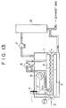
- the conventional drying apparatus for a rotary printing press shown in FIG.13 has the following disadvantages:
- reference numeral 1 denotes a drying apparatus body
- 2 denotes printed paper
- 3 denotes a hot air blowing nozzle
- 4 denotes a preheating burner
- 5 denotes a blower for the first zone
- 6 denotes a blower for the second zone
- 7 denotes an exhaust gas blower
- 8 denotes a direct fired deodorizing apparatus
- 9 denotes a heat recovery apparatus
- 10 denotes a burner for deodorization
- 11 denotes a preheater
- 12 denotes a direct fired reactor
- 13 denotes a hot air temperature control device for regulating burning at the burner 10 for deodorization for the direct fired deodorizing apparatus 8 based on a value detected by a temperature sensor 16 for the hot air blown from the nozzles
- 14 denotes a paper temperature control device for regulating burning at the burner for deodorization 10 in the direct fired deodorizing apparatus 8 based on the value detected by a paper temperature sensor 17, and 15 denote
- the exhaust gas blower 7 is activated to draw the outside air (air for combustion) into the drying apparatus body 1.
- the outside air drawn into the drying apparatus body 1 is directed from the exhaust gas blower 7 to the inside of heat transfer tube of the preheater 11, the direct fired reactor 12, the outside of heat transfer tube of the preheater 11, and the inside of heat transfer tube of the heat recovery apparatus 9 in that sequence.
- the outside air drawn into the drying apparatus body 1 is circulated in the drying apparatus body 1 by activating the blower for the first zone 5 and the blower for the second zone 6. Then, the air circulating in the drying apparatus body 1 is heated by igniting and burning the preheating burner 4.
- the air in the drying apparatus body 1 is directed as the air for combustion from the exhaust gas blower 7 to the inside of heat transfer tube in the preheater 11 and to the direct fired reactor 12. Then, the fuel for the burner for deodorization 10 is ignited and burned. The produced exhaust gas is directed from the outside of heat transfer tube of the preheater 11 to the inside of heat transfer tube of the heat recovery apparatus 9. This exhaust gas, after preheating the air, is discharged out of the drying apparatus body 1.
- the circulating air in the drying apparatus body 1 can be heated rapidly to a specified temperature at the startup before the normal operation.
- the preheating burner 4 is turned off to start the normal operation.
- the paper 2 printed by the rotary printing press is fed into the drying apparatus body 1, while hot air is blown into the paper passage through the hot air blowing nozzles 3 so that the printed paper 2 is exposed to the hot air and the solvent contained in the ink on the paper is evaporated.
- the hot air containing the evaporated solvent (exhaust gas of about 140-170 o C) is returned to the outside of heat transfer tube of heat recovery apparatus 9 at the suction side of the blower for the first zone 5 and the blower for the second zone 6, where the hot air is reheated to about 190-250 o C by the exhaust gas passing through the inside of heat transfer tube of the heat recovery apparatus 9, namely the exhaust gas fed from the direct fired reactor 12 of the direct fired deodorizing apparatus 8 (exhaust gas of about 400-500 o C), and directed to the hot air blowing nozzles 3.
- Part of the hot air in the drying apparatus body 1 is sucked by the exhaust gas blower 7 and fed into the preheater 11 of the direct fired deodorizing apparatus 8, where part of the hot air is preheated by the exhaust gas from the direct fired reactor 12.
- the hot air is directed to the direct fired reactor 12 which is heated to about 700-1000 o C by the burner for deodorization 10, where the evaporated solvent in the hot air is burned for the deodorization of hot air.
- the exhaust gas produced at this time is directed to the inside of heat transfer tube of the heat recovery apparatus 9 for the above-described heat exchanging and is then discharged out of the drying apparatus body 1.
- the heat recovery apparatus 9 can use a shell and tube heat exchanger or a plate type heat exchanger.
- the set value of deodorizing apparatus furnace temperature on the hot air temperature control device 13 is calculated for correction from the value detected by the blowing hot air temperature sensor 16. Based on the result, the burning amount of the burner for deodorization 10 is controlled, and the temperature of hot air blowing from the nozzles is kept at the set value.
- the set value of deodorizing apparatus furnace temperature on the paper temperature control device 14 is calculated for correction from the value detected by the paper temperature sensor 17. Based on the result, the burning at the burner for deodorization 10 is controlled, and the temperature of hot air blowing from the nozzles is kept at the set value.
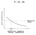
- the conventional drying control device for the rotary printing press shown in FIG. 14 has the following disadvantage: since the deodorizing capability of the direct fired deodorizing apparatus 8 relates directly to the furnace temperature of direct fired reactor 12 as shown in FIG.14, the furnace temperature must be not less than the lower limit T DL in order to comply with the regulations regarding the odor concentration. For the conventional drying control device for the rotary printing press shown in FIG.14, nevertheless, the furnace temperature of the direct fired deodorizing apparatus 8 is not controlled. For example, in the paper temperature control, when the thermal load is decreased (for example, when the printing speed decreases), the burning amount of the burner for deodorization 10 is decreased, sometimes resulting in a decrease in deodorizing apparatus furnace temperature down to a value less than the lower limit.
- the controllability is not high because the blowing hot air temperature does not respond to the temperature change in the reaction furnace 12 since the heat capacity of the heat exchanger 9 is high, when a speed change (i.e., thermal load fluctuation) occurs in the printing press or when an attempt is made to change a control target value (instrumental set value) of blowing hot air temperature.
- a speed change i.e., thermal load fluctuation
- the hot air can be heated in about one minute by using the preheating burner 4 at the startup, but the apparatus has no effective mechanism for cooling the hot air when the printing speed is decreased due to troubles or adjustments in the printing press during the normal operation. That is, the responsiveness of paper temperature is very low because the deodorizing apparatus furnace temperature has a lower limit for providing proper deodorizing capability and because the heat capacity of the heat exchanger is high. Therefore, the paper temperature exceeds the specified value for a long period of time, resulting in a heavy paper loss.
- the object of this invention is to provide a drying apparatus in which the deodorizing apparatus furnace temperature is kept at a specified value, and the deodorizing apparatus furnace temperature does notdecrease to a value less than the lower limit when the thermal load, such as the printing speed, changes.
- a drying apparatus for rotary printing press in which hot air is blown onto printed paper to dry the printed paper by evaporating the solvent in ink, and this hot air is reheated by using the exhaust gas from the direct fired deodorizing apparatus, and which comprises a hot air temperature control device for correcting the set value of deodorizing apparatus furnace temperature on the basis of the value detected by blowing hot air temperature sensor, a paper temperature control device for correcting the set value of deodorizing apparatus furnace temperature on the basis of the value detected by the paper temperature sensor, and a deodorising apparatus furnace temperature control device for calculating the deodorizing apparatus furnace temperature on the basis of the corrected set value from the hot air temperature control device or the paper temperature control device and for controlling the burning at the burner for deodorization of the direct fired deodorizing apparatus on the basis of the calculation result.
- a hot air temperature control device for correcting the set value of deodorizing apparatus furnace temperature on the basis of the value detected by blowing hot air temperature sensor
- a paper temperature control device for correcting the set value of deodorizing apparatus furnace
- the drying apparatus for rotary printing press is constructed as described above, when drying is performed by paper temperature control, the set value of deodorizing apparatus furnace temperature on the paper temperature control device is corrected on the basis of the value detected by the paper temperature sensor, and the result is sent to the deodorizing apparatus furnace temperature control device. Based on the corrected set value and the value detected by the deodorizing apparatus furnace temperature sensor, the set value of deodorizing apparatus furnace temperature on the deodorizing apparatus furnace temperature control device is calculated. The calculation result is used to control the burning amount of the burner for deodorization to keep the paper temperature at the set value.
- a bypass line is installed on the first zone hot air circulation line to bypass the heat recovery apparatus 9, and the bypass amount is controlled by the paper temperature on the drying apparatus side or by the blowing hot air temperature in order to give a drying apparatus having high control responsiveness.
- a means is provided to simultaneously control the furnace temperature of the direct fired reactor 12 on the basis of the blowing hot air temperature.
- the heat capacity is lowered because the hot air in the first zone hot air circulation line is bypassed without passing through the heat recovery apparatus. Therefore, the temperature of blowing hot air is rapidly changed by controlling the deodorizing apparatus furnace temperature, which enables the control to be carried out so that the paper temperature remains constant.
- the paper temperature control device 14 When the printing speed decreases during the operation of printing press, the paper temperature rises. Then, the paper temperature control device 14 operates the bypass damper 21 in the opening direction. Since the heat recovery apparatus 9, which is a heat source of hot air, is bypassed, the temperature of blowing hot air in the first zone is decreased, and at the same time the paper temperature returns to the original value.
- part of the hot air from the blower 5 is directed to the heat recovery apparatus and joins to the hot air passing through the bypass line 20 at the exit side of the heat recovery apparatus 9. At this time, if the temperature of exhaust gas from the deodorizing apparatus 8 is high, the hot air temperature decreasing effect is inhibited. There is also a problem of heat resistance of the heat transfer tube of the heat recovery apparatus 9. Therefore, the arithmetic unit 26 calculates the set value of deodorizing apparatus furnace temperature in accordance with the printing speed, that is the thermal load of printed paper, to reduce the set value.
- the deodorizing apparatus furnace temperature control device 25 controls the burning amount of the burner for deodorization in response to the change in the set value.
- an object of this invention is to provide a drying apparatus for rotary printing press with high control responsiveness as compared with the drying apparatus disclosed in the Japanese Patent Application No. 083912/1989.
- a bypass line is installed on the first zone heat recovery line to bypass the heat recovery apparatus 9, and the bypass amount is controlled by the paper temperature at the exit side of drying apparatus or by the blowing hot air temperature.
- a means is provided to simultaneously control the furnace temperature of the direct fired reactor 12 based on the blowing hot air temperature or the paper temperature on the exit side of drying apparatus.
- the heating amount of hot air in the first zone circulation line can be quickly controlled by directing part of the hot air in the heat recovery line to the bypass line.
- the temperature of blowing hot air is rapidly changed, enabling the control to be carried out so that the paper temperature is constant.
- FIG.1 The first embodiment of the drying apparatus for rotary printing press according to the first aspect of this invention is shown in FIG.1.
- Reference numeral 1 denotes a drying apparatus body
- 2 denotes printed paper
- 3 denotes a hot air blowing nozzle
- 4 denotes a preheating burner
- 5 denotes a blower for the first zone
- 6 denotes a blower for the second zone
- 7 denotes an exhaust gas blower
- 8 denotes a direct fired deodorizing apparatus
- 9 denotes a heat recovery apparatus
- 10 denotes a burner for deodorization
- 11 denotes a preheater
- 12 denotes a direct fired reactor
- 13 denotes a hot air temperature control device
- 14 denotes a paper temperature control device
- 15 denotes a selector switch
- 16 denotes a blowing hot air temperature sensor
- 17 denotes a paper temperature sensor
- 18 denotes a control device for deodorizing apparatus furnace
- the set value of deodorizing apparatus furnace temperature on the hot air temperature control device 13 is corrected on the basis of the value detected by the blowing hot air temperature sensor 16. The result is sent to the deodorizing apparatus furnace temperature control device 18.
- the set value in the control device 18 of deodorizing apparatus furnace temperature is calculated from this corrected set value and the detected value obtained from the deodorizing apparatus furnace temperature sensor 19. Based on the result, the burning amount of the burner for deodorization 10 is controlled, and the temperature of hot air blowing from the nozzles is kept at the set value.
- the set value of deodorizing apparatus furnace temperature on the paper temperature control device 14 is corrected on the basis of the value detected by the paper temperature sensor 17. The result is sent to the deodorizing apparatus furnace temperature control device 18.
- the set value of deodorizing apparatus furnace temperature is calculated from this corrected set value and the detected value obtained from the deodorizing apparatus furnace temperature sensor 19. Based on the result, the burning amount of the burner for deodorization 10 is controlled, and the temperature of hot air blowing from the nozzles is kept at the set value.
- the set value for deodorizing apparatus furnace temperature on the paper temperature control device 14 is reduced on the basis of the value detected by the paper temperature sensor 17.
- the set value of deodorizing apparatus furnace temperature on the deodorising apparatus furnace temperature control device 18 is calculated from the reduced set value and the detected value obtained from the deodorizing apparatus furnace temperature sensor 19. Based on the result, the burning amount of the burner for deodorization 10 is decreased to keep the paper temperature at the set value.
- the set value of deodorizing apparatus furnace temperature on the paper temperature control device is corrected on the basis of the value detected by the paper temperature sensor, and the result is sent to the deodorizing apparatus furnace temperature control device.
- the set value of deodorizing apparatus furnace temperature on the deodorizing apparatus furnace temperature control device is calculated from the corrected set value and the detected value obtained from the deodorizing apparatus furnace temperature sensor. Based on the result, the burning amount of the burner for deodorization is controlled to keep the paper temperature at the set value.
- the deodorizing apparatus furnace temperature can be kept at the set value when the printing speed or other thermal load is changed, so that the deodorizing apparatus furnace temperature is not decreased to a value less than the lower limit.
- reference numeral 1 denotes a drying apparatus body
- 2 denotes printed paper
- 3 denotes a hot air blowing nozzle
- 4 denotes a preheating burner
- 5 denotes a blower for the first zone
- 6 denotes a blower for the second zone
- 7 denotes an exhaust gas blower
- 8 denotes a direct fired deodorizing apparatus
- 9 denotes a heat recovery apparatus
- 10 denotes a burner for deodorization
- 11 denotes a preheater
- 12 denotes a direct fired reactor
- 16 denotes a hot air temperature sensor for the first zone
- 17 denotes a paper temperature sensor
- 20 denotes a bypass line
- 21 denotes an automatic bypass damper
- 22 denotes a motor or cylinder
- 23 denotes a function generator
- 24 denotes a deodorizing apparatus furnace temperature sensor
- TIC-1 denotes a paper temperature regulator
- TIC-2 denotes a
- the principal configuration of this embodiment is the same as that of the drying apparatus shown in FIG.14, except that a bypass line 20 is installed on the first zone hot air circulation line, and an automatic bypass damper 21 is disposed midway in the line 20.
- the paper temperature regulator TIC-1 is linked to the motor 22 (or cylinder) disposed to the automatic bypass damper 21 and the preheating burner 4 for startup in order to send control signals.
- the odorizing apparatus furnace temperature regulator TIC-2 controls the burning amount of the burner for deodorization so that the furnace temperature obtained from the deodorizing apparatus furnace temperature sensor 24 takes a specified value, via the function generator 23 which calculates the output in accordance with the temperature signal of the first zone hot air temperature sensor 16.
- the exhaust gas blower 7 is activated to draw the outside air (air for combustion) into the drying apparatus body 1.
- the outside air drawn into the drying apparatus body 1 is directed from the exhaust gas blower 7 to the inside of heat transfer tube of the preheater 11, the direct fired reactor 12, the outside of heat transfer tube of the preheater 11, and the inside of heat transfer tube of the heat recovery apparatus 9 in that sequence.
- the outside air drawn into the drying apparatus body 1 is circulated in the drying apparatus body 1 by activating the blower for the first zone 5 and the blower for the second zone 6. Then, the air circulating in the drying apparatus body 1 is heated by igniting and burning the preheating burner 4.
- the air in the drying apparatus body 1 is directed as the air for combustion from the exhaust gas blower 7 to the inside of heat transfer tube in the preheater 11 and to the direct fired reactor 12. Then, the fuel for the burner for deodorization 10 is ignited and burned. The produced exhaust gas is directed from the outside of heat transfer tube of the preheater 11 to the inside of heat transfer tube of the heat recovery apparatus 9. This exhaust gas, after preheating the air circulating in the drying apparatus body 1, is discharged out of the drying apparatus body 1. Thus, the circulating air in the drying apparatus body 1 can be heated rapidly to a specified temperature at the startup before the normal operation.
- the preheating burner 4 is turned off to start the normal operation.
- the paper 2 printed by the rotary printing press is fed into the drying apparatus body 1, while hot air is blown into the paper passage through the hot air blowing nozzles 3 so that the printed paper 2 is exposed to the hot air and the solvent contained in the ink on the paper is evaporated.
- the hot air containing the evaporated solvent (exhaust gas of about 140-170 o C) is returned to the outside of heat transfer tube of heat recovery apparatus 9 at the suction side of the blower for the first zone 5 and the blower for the second zone 6, where the hot air is reheated to about 190-250 o C by the exhaust gas passing through the inside of heat transfer tube of the heat recovery apparatus 9, namely the exhaust gas fed from the direct fired reactor 12 of the direct fired deodorizing apparatus 8 (exhaust gas of about 400-500 o C), and directed to the hot air blowing nozzles 3.
- Part of the hot air in the drying apparatus body 1 is sucked by the exhaust gas blower 7 and fed into the preheater 11 of the direct fired deodorizing apparatus 8, where part of the hot air is preheated by the exhaust gas from the direct fired reactor 12.
- the hot air is directed to the direct fired reactor 12 which is heated to about 700-1000 o C by the burner for deodorization 10, where the evaporated solvent in the hot air is burned for the deodorization of hot air.
- the exhaust gas produced at this time is directed to the inside of heat transfer tube of the heat recovery apparatus 9 for the above-described heat exchanging and is then discharged out of the drying apparatus body 1.
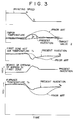
- FIG.3 shows the relationship between the degree of opening of the control damper 21 disposed in the first zone hot air circulation line 20 and the paper temperature (temperature sensor 17) or the hot air blowing temperature (temperature sensor 16) and also the relationship between the degree of opening of the control damper 21 and the furnace temperature of the direct fired reactor 12.
- the hot air temperature in the first zone T1 is suddenly decreased, and the paper temperature is soon returned to the target value Z.
- the drying of printed paper can be controlled with high responsiveness to the change in printing speed by controlling the furnace temperature of the deodorizing apparatus 8 corresponding to the hot air temperature in the first zone while controlling the degree of opening of the bypass damper 21 in the first zone circulation line 20 so that the paper temperature is constant.
- the temperature of printed paper begins increasing gradually from 125 o C.
- the paper temperature returns to the set value within one minute according to this invention, whereas it returns to the set value in 5-10 minutes in the apparatus disclosed in the Japanese Patent Application No. 083912/1989.
- a bypass line is installed on the hot air circulation line to bypass the heat recovery apparatus to control the paper temperature and/or blowing hot air temperature by regulating the degree of opening of bypass damper installed in the bypass line, and to control the burning amount of the burner for deodorization so that the deodorizing apparatus furnace temperature corresponding to the blowing hot air temperature is obtained. Therefore, this drying apparatus of this invention achieves the following effects:
- 1 denotes a drying apparatus body
- 2 denotes printed paper
- 3 denotes a hot air blowing nozzle
- 4 denotes a preheating burner
- 5 denotes a blower for the first zone
- 6 denotes a blower for the second zone
- 7 denotes an exhaust gas blower
- 8 denotes a direct fired deodorizing apparatus
- 9 denotes a heat recovery apparatus
- 10 denotes a burner for deodorization
- 11 denotes a preheater
- 12 denotes a direct fired reactor
- 14 denotes a paper temperature control device
- 17 denotes a paper temperature sensor
- 20 denotes a bypass line
- 21 denotes a damper
- 22 denotes a motor (or cylinder)
- 24 denotes a deodorizing apparatus furnace temperature sensor
- 25 denotes a deodorizing apparatus furnace temperature control device
- 26 denotes a control output setting device
- 27 denotes a printing speed sensor
- the bypass line 20 is installed on the first zone hot air circulation line, and the damper 21 is disposed midway in the bypass line 20.
- the paper temperature control device 14 is connected to the motor (or cylinder) 22 via the transducer 28, and to the preheating burner 4 via the transducer 29.
- the operations of transducers 28 and 29 are shown in FIG.5 and 6, respectively.
- a lower limit temperature for the deodorizing apparatus furnace temperature control device 25 is set to provide a desired deodorizing capability.
- the deodorizing apparatus furnace temperature control device 25 controls the burning amount of the burner for deodorization 10 so that the deodorizing apparatus furnace temperature detected by the sensor 24 is equal to the set value.
- the control output setting device 26 provides a reset value of output of the paper temperature control device 14. While the printing speed sensor 27 detects printing speeds at a regular intervals t p , the control output setting device 26 outputs the reset value in accordance with the change rate of printing speed with time ( ⁇ V s /t p ). The paper temperature control device 14 resumes the PID (proportional-integral-derivative) operation with the reset value being used as the initial value.
- FIG.7 shows a typical operation of the preset manual setting device. This figure indicates that when
- FIG.8 shows further details of the configuration.
- reference numeral 30 denotes an arithmetic unit for the change rate of printing speed with time, which performs the following calculations at regular intervals (usually on the order of several seconds) t p .
- k printing speed detection time
- V S (k) detected value of printing speed at the kth time point
- t p calculation interval
- ⁇ V s / ⁇ t change rate of printing speed with time.
- the control output setting device 26 performs the following operations in accordance with the change rate of printing speed with time obtained from the arithmetic unit for the change rate of printing speed with time 30 at calculation intervals of t p (the details of operation is shown in FIG.7), and outputs the operation result C VR (reset value of paper temperature control device output) and f (flag) for the paper temperature control device 14.
- C VR reset value of paper temperature control device output
- f flag
- x1, x2, y1 , y2, ⁇ parameter given in advance.
- the paper temperature control device 14 outputs the control output C V by the procedure shown in FIG.9 from the input data of paper temperature detected by the paper temperature sensor 17, target value of paper temperature obtained from the setting device 31, and C VR and f obtained from the control output setting device 26.
- the paper temperature control device 14 performs the normal PID operation (the details are omitted).
- the normal PID operation is not performed, but the paper temperature control device output is forcedly reset to the obtained control output value C VR in accordance with the change rate of printing speed with time.
- f returns from 1 to 0 (the speed becomes constant)
- the PID operation is resumed with the reset value being used as the initial value.
- the transducers 28 and 29 perform the operation shown in FIGS.5 and 6 in accordance with C V . They determine the command value for the degree of opening for bypass damper and the command value for the degree of opening of preheating burner valve, respectively, to control the degree of opening of bypass damper and preheating burner valve.
- the drying apparatus for rotary printing press for drying the ink on the printed paper by the hot air heating method which has a direct fired deodorizing apparatus and a heat recovery apparatus for reheating the hot air circulating in the drying apparatus by using the exhaust gas from the deodorizing apparatus
- the drying apparatus comprises a bypass line installed on the hot air circulation line to bypass the heat recovery apparatus, a control device for controlling the paper surface temperature to be the set value by regulating the degree of opening of damper installed in the bypass line or the burning amount of preheating burner, and a control output setting device for resetting the output value of the control device to a predetermined value in according with the change rate of printing speed with time when the change rate of printing speed with time exceeds a specified value. Therefore, this drying apparatus of this invention achieves the following effect.
- the heat recovery apparatus which is a heat source, is bypassed and the bypass amount is quickly changed in accordance with the change rate of printing speed, so that control can be performed without delay.
- the temperature of hot air is rapidly decreased, enabling the control of paper temperature to be carried out with high responsiveness. This increases the yield of product and decreases the loss of paper.
- 1 denotes a drying apparatus body
- 2 denotes printed paper
- 3 denotes a hot air blowing nozzle
- 4 denotes a preheating burner
- 5 denotes a blower for the first zone
- 6 denotes a blower for the second zone
- 7 denotes an exhaust gas blower
- 8 denotes a direct fired deodorizing apparatus
- 9 denotes a heat recovery apparatus
- 10 denotes a burner for deodorization
- 11 denotes a preheater
- 12 denotes a direct fired reactor
- 14 denotes a paper temperature control device
- 17 denotes a paper temperature sensor
- 20 denotes a bypass line
- 21 denotes a damper
- 22 denotes a motor for damper
- 24 denotes a deodorizing apparatus furnace temperature sensor
- 25 denotes a deodorizing apparatus furnace temperature control device
- 26 denotes an arithmetic unit
- 27 denotes a printing speed sensor
- the bypass line 20 is installed on the first zone hot air circulation line, and the damper is disposed midway in the line 20.
- the paper temperature control device 14 is connected to the motor (or cylinder) mounted to the damper 21 and the preheating burner 4. The operator can change over the connection with the selector switch 33. The connection may be changed over in accordance with the increase/decrease in printing speed. At the moment when the connection is changed over, the output of the paper temperature control device 14 is reset to 0. (That is, the degree of opening of damper or preheating burner valve is 0.)
- the deodorizing apparatus furnace temperature control device 25 controls the burning amount of the burner for deodorization 10 so that the value detected by the deodorizing apparatus furnace temperature sensor 24 is equal to the set value which is the output of the arithmetic unit 26.
- the arithmetic unit 26 calculates the thermal load Q S in accordance with the printing speed obtained from the paper speed sensor 27 and the printing conditions a which is inputted by the operator(G, W, T S shown below) by using, for example, the following equation.
- Q S V ⁇ G ⁇ W ⁇ (T S - T O ) ⁇ C Eq.3
- Q S quantity of heat received by paper (Kcal/h)
- V printing speed (m/h)
- G basis weight of printed paper (kg/m2)
- W width of printed paper (m)
- T S target value of paper temperature ( o C)
- T O paper temperature at the entrance of drying apparatus ( o C)
- C specific heat of printed paper (Kcal/kg o C).
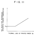
- the set value of deodorizing apparatus furnace temperature is determined in accordance with Q S by using the relationship shown, for example, in FIG.11, and sent to the deodorizing apparatus furnace temperature control device 25.
- the symbol T DL in FIG.11 denotes the lower limit temperature satisfying proper deodorizing requirements.
- the drying apparatus for rotary printing press for drying the ink on the printed paper by the hot air heating method which has a direct fired deodorizing apparatus and a heat recovery apparatus for reheating the hot air circulating in the drying apparatus by the exhaust gas from the deodorizing apparatus
- the drying apparatus comprises a bypass line installed on the hot air circulation line to bypass the heat recovery apparatus, a control device for controlling the paper surface temperature to be the set value by operating the degree of opening of damper installed in the bypass line or the burning amount of preheating burner, and an arithmetic unit for calculating the set value of deodorizing apparatus furnace temperature in accordance with the thermal load of printed paper obtained by the detection of printing speed, and a control device for controlling the deodorizing apparatus furnace temperature to be the set value by controlling the burning amount of the burner for deodorization. Therefore, this drying apparatus of this invention achieves the following effect.
- the temperature of hot air is quickly decreased by bypassing the heat recovery apparatus, enabling the control of paper temperature to be carried out with high responsiveness. This increases the yield of product and decreases the loss of paper.
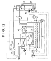
- reference numeral 1 denotes a drying apparatus body
- 2 denotes printed paper
- 3 denotes a hot air blowing nozzle
- 4 denotes a preheating burner
- 5 denotes a blower for the first zone
- 6 denotes a blower for the second zone
- 7 denotes an exhaust gas blower
- 8 denotes a direct fired deodorizing apparatus
- 9 denotes a heat recovery apparatus
- 10 denotes a burner for deodorization
- 11 denotes a preheater
- 12 denotes a direct fired reactor
- 16 denotes a hot air temperature sensor for the first zone
- 17 denotes a paper temperature sensor
- 20 denotes a bypass line of the heat recovery line
- 21 denotes an automatic bypass damper
- 22 denotes a motor or cylinder
- 23 denotes a function generator
- 24 denotes a deodorizing apparatus furnace temperature sensor
- TIC-1 denotes a paper temperature regulator
- TIC-2
- the principal configuration of this embodiment is the same as that of the drying apparatus shown in FIG.14, except that a bypass line 20 is installed on the first zone hot air circulation line, and an automatic bypass damper 21 is disposed midway in the line 20.
- the paper temperature regulator TIC-1 is linked to the motor 22 (or cylinder) mounted to the automatic bypass damper 21 and the preheating burner for startup 4 to send control signals.
- the odorizing apparatus furnace temperature regulator TIC-2 controls the burning amount of the burner for deodorization so that the furnace temperature obtained from the deodorizing apparatus furnace temperature sensor 24 takes a specified value, via the function generator 23 which calculates the output in accordance with the temperature signal of the first zone hot air temperature sensor 16.
- the equivalent effect can be achieved when TIC-2 performs the control via a function generator 23' which calculates the output in accordance with the temperature signal of the paper temperature sensor 17.
- the exhaust gas blower 7 is activated to draw the outside air (air for combustion) into the drying apparatus body 1.
- the outside air drawn into the drying apparatus body 1 is directed from the exhaust gas blower 7 to the inside of heat transfer tube of the preheater 11, the direct fired reactor 12, the outside of heat transfer tube of the preheater 11, and the inside of heat transfer tube of the heat recovery apparatus 9 in that sequence.
- the outside air drawn into the drying apparatus body 1 is circulated in the drying apparatus body 1 by activating the blower for the first zone 5 and the blower for the second zone 6. Then, the air circulating in the drying apparatus body 1 is heated by igniting and burning the preheating burner 4.
- the air in the drying apparatus body 1 is directed as the air for combustion from the exhaust gas blower 7 to the inside of heat transfer tube in the preheater 11 and to the direct fired reactor 12. Then, the fuel for the burner for deodorization 10 is ignited and burned. The produced exhaust gas is directed from the outside of heat transfer tube of the preheater 11 to the inside of heat transfer tube of the heat recovery apparatus 9. This exhaust gas, after preheating the air circulating in the drying apparatus body 1, is discharged out of the drying apparatus body 1. Thus, the circulating air in the drying apparatus body 1 can be heated rapidly to a specified temperature at the startup before the normal operation.
- the preheating burner 4 is turned off to start the normal operation.
- the paper 2 printed by the rotary printing press is fed into the drying apparatus body 1, while hot air is blown into the paper passage through the hot air blowing nozzles 3 so that the printed paper 2 is exposed to the hot air and the solvent contained in the ink on the paper is evaporated.
- the hot air containing the evaporated solvent (exhaust gas of about 140-170 o C) is returned to the outside of heat transfer tube of heat recovery apparatus 9 at the suction side of the blower for the first zone 5 and the blower for the second zone 6, where the hot air is reheated to about 190-250 o C by the exhaust gas passing through the inside of heat transfer tube of the heat recovery apparatus 9, namely the exhaust gas fed from the direct fired reactor 12 of the direct fired deodorizing apparatus 8 (exhaust gas of about 400-500 o C), and directed to the hot air blowing nozzles 3.
- Part of the hot air in the drying apparatus body 1 is sucked by the exhaust gas blower 7 and fed into the preheater 11 of the direct fired deodorizing apparatus 8, where part of the hot air is preheated by the exhaust gas from the direct fired reactor 12.
- the hot air is directed to the direct fired reactor 12 which is heated to about 700-1000 o C by the burner for deodorization 10, where the evaporated solvent in the hot air is burned for the deodorization of hot air.
- the exhaust gas produced at this time is directed to the inside of heat transfer tube of the heat recovery apparatus 9 for the above-described heat exchanging and is then discharged out of the drying apparatus body 1.
- FIG.3 shows the relationship between the degree of opening of the control damper 21 disposed in the first zone hot air circulation line 20 and the paper temperature (temperature sensor 17) or the hot air blowing temperature (temperature sensor 16) and also the relationship between the degree of opening of the control damper 21 and the furnace temperature of the direct fired reactor 12.
- the furnace temperature of the deodorizing apparatus 8 decreases with the decrease in the first zone hot air temperature T1 or with the increase in the paper temperature T S , so that a certain heat recovery rate can be secured.
- the drying of printed paper can be controlled with high responsiveness to the change in printing speed by regulating the furnace temperature in the deodorizing apparatus 8 corresponding to the first zone hot air temperature or the paper temperature while controlling the degree of opening of the bypass damper 21 in the first zone circulation line 20 so that the paper temperature is constant.
- the temperature of printed paper begins increasing gradually from 125 o C.
- the paper temperature returns to the set value within one minute according to this invention, whereas it returns to the set value in 5-10 minutes in the apparatus disclosed in the Japanese Patent Application No. 083912/1989.
- a bypass line is installed on the hot air circulation line to bypass the heat recovery apparatus to control the paper temperature and/or blowing hot air temperature by regulating the degree of opening of bypass damper disposed in the bypass line, and the burning amount of the burner for deodorization is controlled so that the deodorizing apparatus furnace temperature corresponding to the blowing hot air temperature or paper temperature is obtained. Therefore, this drying apparatus of this invention achieves the following effects:
Landscapes
- Engineering & Computer Science (AREA)
- Mechanical Engineering (AREA)
- Chemical & Material Sciences (AREA)
- Combustion & Propulsion (AREA)
- Life Sciences & Earth Sciences (AREA)
- Sustainable Development (AREA)
- General Engineering & Computer Science (AREA)
- Supply, Installation And Extraction Of Printed Sheets Or Plates (AREA)
- Drying Of Solid Materials (AREA)
Priority Applications (1)
| Application Number | Priority Date | Filing Date | Title |
|---|---|---|---|
| EP94111630A EP0629500B1 (de) | 1990-12-03 | 1991-11-29 | Trocknungsvorrichtung für Rotationsdruckmaschine |
Applications Claiming Priority (4)
| Application Number | Priority Date | Filing Date | Title |
|---|---|---|---|
| JP2400261A JPH04212859A (ja) | 1990-12-03 | 1990-12-03 | 輪転印刷機ドライヤの紙面温度制御装置 |
| JP400261/90 | 1990-12-03 | ||
| JP408230/90 | 1990-12-27 | ||
| JP2408230A JPH04224953A (ja) | 1990-12-27 | 1990-12-27 | 輪転印刷機の乾燥装置 |
Related Child Applications (1)
| Application Number | Title | Priority Date | Filing Date |
|---|---|---|---|
| EP94111630.3 Division-Into | 1994-07-26 |
Publications (2)
| Publication Number | Publication Date |
|---|---|
| EP0489366A1 true EP0489366A1 (de) | 1992-06-10 |
| EP0489366B1 EP0489366B1 (de) | 1995-10-18 |
Family
ID=26582872
Family Applications (2)
| Application Number | Title | Priority Date | Filing Date |
|---|---|---|---|
| EP91120514A Expired - Lifetime EP0489366B1 (de) | 1990-12-03 | 1991-11-29 | Trocknungsvorrichtung und ihre Steuervorrichtung für Rotationsdruckmaschine |
| EP94111630A Expired - Lifetime EP0629500B1 (de) | 1990-12-03 | 1991-11-29 | Trocknungsvorrichtung für Rotationsdruckmaschine |
Family Applications After (1)
| Application Number | Title | Priority Date | Filing Date |
|---|---|---|---|
| EP94111630A Expired - Lifetime EP0629500B1 (de) | 1990-12-03 | 1991-11-29 | Trocknungsvorrichtung für Rotationsdruckmaschine |
Country Status (3)
| Country | Link |
|---|---|
| US (1) | US5203092A (de) |
| EP (2) | EP0489366B1 (de) |
| DE (2) | DE69126148T2 (de) |
Cited By (1)
| Publication number | Priority date | Publication date | Assignee | Title |
|---|---|---|---|---|
| DE4309266A1 (de) * | 1993-03-23 | 1994-09-29 | Heidelberger Druckmasch Ag | Verfahren zur Steuerung der Einschaltung des Papierlaufes einer Druckmaschine |
Families Citing this family (7)
| Publication number | Priority date | Publication date | Assignee | Title |
|---|---|---|---|---|
| SE517939C2 (sv) * | 2000-05-10 | 2002-08-06 | Interflaekt I Tullinge Ab | Förfarande och anordning för att torka ett arkformigt alster |
| CN101073938A (zh) * | 2006-05-17 | 2007-11-21 | 海德堡印刷机械股份公司 | 用于在单张纸印刷机中干燥页张的装置 |
| DE102011075109A1 (de) * | 2010-05-11 | 2011-11-17 | Manroland Ag | Thermoluft-Trocknungseinrichtung mit Abwärmenutzung |
| CN102514370A (zh) * | 2011-12-08 | 2012-06-27 | 杨峥雄 | 一种印刷涂布机烘干箱及节能方法 |
| WO2019236097A1 (en) * | 2018-06-08 | 2019-12-12 | Hewlett-Packard Development Company, L.P. | Media conditioning |
| CN110077104B (zh) * | 2019-05-24 | 2020-12-15 | 鸿博昊天科技有限公司 | 一种具有气体循环装置的环保印刷机 |
| US20210302096A1 (en) * | 2019-08-15 | 2021-09-30 | Tyler Player | Drying Apparatus and Method of Drying |
Citations (4)
| Publication number | Priority date | Publication date | Assignee | Title |
|---|---|---|---|---|
| US4150495A (en) * | 1978-05-03 | 1979-04-24 | Bobst-Champlain, Inc. | LEL (lower explosive limit) control with automatic calibration capability |
| US4341167A (en) * | 1980-10-29 | 1982-07-27 | St John Eric P | Energy conserving heating and cooling system for printing plant |
| DE3616333C1 (de) * | 1986-05-15 | 1987-04-16 | Krantz H Gmbh & Co | Verfahren zum thermischen Reinigen der Abgase einer Waermebehandlungsvorrichtung |
| EP0273230A2 (de) * | 1986-12-23 | 1988-07-06 | Brückner Trockentechnik GmbH & Co. KG | Verfahren und Einrichtung zur thermischen Behandlung einer kontinuierlich bewegten textilen Wahrenbahn |
Family Cites Families (4)
| Publication number | Priority date | Publication date | Assignee | Title |
|---|---|---|---|---|
| US3909953A (en) * | 1974-02-28 | 1975-10-07 | Midland Ross Corp | Paint drying method and apparatus |
| JPS58175662A (ja) * | 1982-04-09 | 1983-10-14 | Toshiba Mach Co Ltd | 印刷機の脱臭装置付き乾燥炉 |
| JP2772794B2 (ja) * | 1987-09-24 | 1998-07-09 | ヤマハ発動機株式会社 | クランク軸と連接棒との連結部構造 |
| US4942676A (en) * | 1988-06-07 | 1990-07-24 | W. R. Grace & Co.-Conn. | Control system for air flotation dryer with a built-in afterburner |
-
1991
- 1991-11-29 DE DE69126148T patent/DE69126148T2/de not_active Expired - Fee Related
- 1991-11-29 DE DE69113959T patent/DE69113959T2/de not_active Expired - Fee Related
- 1991-11-29 EP EP91120514A patent/EP0489366B1/de not_active Expired - Lifetime
- 1991-11-29 EP EP94111630A patent/EP0629500B1/de not_active Expired - Lifetime
- 1991-12-02 US US07/801,461 patent/US5203092A/en not_active Expired - Fee Related
Patent Citations (4)
| Publication number | Priority date | Publication date | Assignee | Title |
|---|---|---|---|---|
| US4150495A (en) * | 1978-05-03 | 1979-04-24 | Bobst-Champlain, Inc. | LEL (lower explosive limit) control with automatic calibration capability |
| US4341167A (en) * | 1980-10-29 | 1982-07-27 | St John Eric P | Energy conserving heating and cooling system for printing plant |
| DE3616333C1 (de) * | 1986-05-15 | 1987-04-16 | Krantz H Gmbh & Co | Verfahren zum thermischen Reinigen der Abgase einer Waermebehandlungsvorrichtung |
| EP0273230A2 (de) * | 1986-12-23 | 1988-07-06 | Brückner Trockentechnik GmbH & Co. KG | Verfahren und Einrichtung zur thermischen Behandlung einer kontinuierlich bewegten textilen Wahrenbahn |
Non-Patent Citations (2)
| Title |
|---|
| PATENT ABSTRACTS OF JAPAN vol. 15, no. 13 (M-1069)11 January 1991 & JP-A-2 263 648 ( MITSUBISHI HEAVY IND LTD ) 26 October 1990 * |
| PATENT ABSTRACTS OF JAPAN vol. 7, no. 230 (M-249)(1375) 12 October 1983 & JP-A-58 124 113 ( CHIYUUGAI RO KOGYO KK. ) 23 July 1983 * |
Cited By (4)
| Publication number | Priority date | Publication date | Assignee | Title |
|---|---|---|---|---|
| DE4309266A1 (de) * | 1993-03-23 | 1994-09-29 | Heidelberger Druckmasch Ag | Verfahren zur Steuerung der Einschaltung des Papierlaufes einer Druckmaschine |
| US5513569A (en) * | 1993-03-23 | 1996-05-07 | Heidelberger Druckmaschinen Ag | Method of controlling a start-up of paper travel in a printing press |
| DE4309266B4 (de) * | 1993-03-23 | 2004-06-09 | Heidelberger Druckmaschinen Ag | Verfahren zur Steuerung der Einschaltung des Papierlaufes einer Druckmaschine |
| DE4309266C5 (de) * | 1993-03-23 | 2008-02-21 | Heidelberger Druckmaschinen Ag | Verfahren zur Steuerung der Einschaltung des Papierlaufes einer Druckmaschine |
Also Published As
| Publication number | Publication date |
|---|---|
| DE69113959T2 (de) | 1996-04-25 |
| DE69126148D1 (de) | 1997-06-19 |
| EP0629500A1 (de) | 1994-12-21 |
| EP0629500B1 (de) | 1997-05-14 |
| DE69126148T2 (de) | 1997-12-04 |
| DE69113959D1 (de) | 1995-11-23 |
| EP0489366B1 (de) | 1995-10-18 |
| US5203092A (en) | 1993-04-20 |
Similar Documents
| Publication | Publication Date | Title |
|---|---|---|
| US4343769A (en) | Catalytic solvent vapor incinerating apparatus | |
| US4548651A (en) | Method for reclaiming contaminated scrap metal | |
| JPH022706B2 (de) | ||
| US5203092A (en) | Drying apparatus and its control device for rotary printing press | |
| US5161488A (en) | System for purifying contaminated air | |
| JPS58207968A (ja) | 乾燥炉内の混合気から溶剤の蒸気を回収する間物質勘定を維持する方法と装置 | |
| EP0502602A1 (de) | Verfahren und Vorrichtung zur Trocknung von beschichteten Warenbahnen | |
| US5186901A (en) | Regenerative bed incinerator system | |
| US4094627A (en) | Oven system | |
| EP0346135B1 (de) | Regelsystem für das Aufwärmen eines auf einem Kraftfahrzeug verwendeten Containers | |
| JP2813421B2 (ja) | 輪転印刷機の乾燥装置 | |
| JPH04224953A (ja) | 輪転印刷機の乾燥装置 | |
| CA1051655A (en) | Oven system | |
| JP3188389B2 (ja) | 塗料の連続乾燥焼付方法 | |
| US5113770A (en) | Apparatus for incinerating waste materials | |
| JPH04305455A (ja) | 輪転印刷機用ドライヤの温度制御装置 | |
| JPS6155008B2 (de) | ||
| JPH0798108A (ja) | 焼却炉における燃焼制御装置 | |
| KR940009318A (ko) | 압력제어가능한 건류 연소 방법 및 건류 연소 장치 | |
| JPH04212859A (ja) | 輪転印刷機ドライヤの紙面温度制御装置 | |
| JPS54147531A (en) | Air preheating temperature controller for combustion of air heating furnaces | |
| JP2745269B2 (ja) | 高温気化冷却装置 | |
| JPH04219243A (ja) | 輪転印刷機用ドライヤの温度制御装置 | |
| SU1802360A1 (en) | Device for controlling air temperature in convective-type drying chamber with heater | |
| JP2003525418A (ja) | 廃棄物などの物質の連続燃焼システム |
Legal Events
| Date | Code | Title | Description |
|---|---|---|---|
| PUAI | Public reference made under article 153(3) epc to a published international application that has entered the european phase |
Free format text: ORIGINAL CODE: 0009012 |
|
| AK | Designated contracting states |
Kind code of ref document: A1 Designated state(s): DE FR GB |
|
| 17P | Request for examination filed |
Effective date: 19920610 |
|
| 17Q | First examination report despatched |
Effective date: 19940318 |
|
| GRAA | (expected) grant |
Free format text: ORIGINAL CODE: 0009210 |
|
| AK | Designated contracting states |
Kind code of ref document: B1 Designated state(s): DE FR GB |
|
| XX | Miscellaneous (additional remarks) |
Free format text: TEILANMELDUNG 94111630.3 EINGEREICHT AM 26/07/94. |
|
| REF | Corresponds to: |
Ref document number: 69113959 Country of ref document: DE Date of ref document: 19951123 |
|
| ET | Fr: translation filed | ||
| PLBE | No opposition filed within time limit |
Free format text: ORIGINAL CODE: 0009261 |
|
| STAA | Information on the status of an ep patent application or granted ep patent |
Free format text: STATUS: NO OPPOSITION FILED WITHIN TIME LIMIT |
|
| 26N | No opposition filed | ||
| REG | Reference to a national code |
Ref country code: GB Ref legal event code: IF02 |
|
| PGFP | Annual fee paid to national office [announced via postgrant information from national office to epo] |
Ref country code: GB Payment date: 20021127 Year of fee payment: 12 |
|
| PGFP | Annual fee paid to national office [announced via postgrant information from national office to epo] |
Ref country code: DE Payment date: 20021205 Year of fee payment: 12 |
|
| PGFP | Annual fee paid to national office [announced via postgrant information from national office to epo] |
Ref country code: FR Payment date: 20031110 Year of fee payment: 13 |
|
| PG25 | Lapsed in a contracting state [announced via postgrant information from national office to epo] |
Ref country code: GB Free format text: LAPSE BECAUSE OF NON-PAYMENT OF DUE FEES Effective date: 20031129 |
|
| PG25 | Lapsed in a contracting state [announced via postgrant information from national office to epo] |
Ref country code: DE Free format text: LAPSE BECAUSE OF NON-PAYMENT OF DUE FEES Effective date: 20040602 |
|
| GBPC | Gb: european patent ceased through non-payment of renewal fee |
Effective date: 20031129 |
|
| PG25 | Lapsed in a contracting state [announced via postgrant information from national office to epo] |
Ref country code: FR Free format text: LAPSE BECAUSE OF NON-PAYMENT OF DUE FEES Effective date: 20050729 |
|
| REG | Reference to a national code |
Ref country code: FR Ref legal event code: ST |