EP0489464A1 - Bett mit verstellbarer Liegefläche, insbesondere für Krankenwagen - Google Patents
Bett mit verstellbarer Liegefläche, insbesondere für Krankenwagen Download PDFInfo
- Publication number
- EP0489464A1 EP0489464A1 EP91203120A EP91203120A EP0489464A1 EP 0489464 A1 EP0489464 A1 EP 0489464A1 EP 91203120 A EP91203120 A EP 91203120A EP 91203120 A EP91203120 A EP 91203120A EP 0489464 A1 EP0489464 A1 EP 0489464A1
- Authority
- EP
- European Patent Office
- Prior art keywords
- track
- upper structure
- bed
- mobile element
- along
- Prior art date
- Legal status (The legal status is an assumption and is not a legal conclusion. Google has not performed a legal analysis and makes no representation as to the accuracy of the status listed.)
- Withdrawn
Links
- 230000000452 restraining effect Effects 0.000 claims description 4
- 210000000056 organ Anatomy 0.000 description 2
- 230000002459 sustained effect Effects 0.000 description 2
- 238000010276 construction Methods 0.000 description 1
- 230000002349 favourable effect Effects 0.000 description 1
Images
Classifications
-
- A—HUMAN NECESSITIES
- A61—MEDICAL OR VETERINARY SCIENCE; HYGIENE
- A61G—TRANSPORT, PERSONAL CONVEYANCES, OR ACCOMMODATION SPECIALLY ADAPTED FOR PATIENTS OR DISABLED PERSONS; OPERATING TABLES OR CHAIRS; CHAIRS FOR DENTISTRY; FUNERAL DEVICES
- A61G1/00—Stretchers
- A61G1/06—Supports for stretchers, e.g. to be placed in or on vehicles
Definitions
- This invention relates to a bed with adjustable laying surface, in particular suitable for ambulances.
- the invention involves beds that include a fixed base relative to the surface (in particular, attached to the floor of the ambulance); an upper structure that sustains the laying surface on which the people (ill or injured) are placed; and a support frame for the upper structure including mobile parts on vertical planes whose movement determines the vertical movement of the upper structure.
- the bed laying surface can be a stretcher that is placed on the upper structure and restrained by it, or it can be a surface fixed directly onto the upper structure.
- Some beds of this type already exist that differ in the structure of their support frames and that generally utilise fluidic jacks to mechanically extend or retract the support frame in order to raise or lower the bed surface and to adjust the inclination.
- An object of the present invention is to create a bed with a laying surface that is adjustable in both height and inclination, in which the space occupied by the bed in the completely lowered position would be extremely limited especially in height.
- Another object of the present invention is to create a bed whose laying surface can be raised or lowered by motorised means that require relatively low levels of electrical power; this in order to be able to use the batteries with which the vehicle is usually equipped instead of special energy sources.
- Another object of the present invention is to create a bed which, in addition to achieving the above-mentioned objectives, would be simple and economical in terms of its construction.
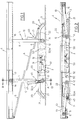
- the bed illustrated in the figures includes substantially a base 2 attached to the floor 3 of the ambulance, an upper structure 4 for sustaining the laying surface of the bed (for example, for holding a stretcher, not illustrated, on which the person is laid) and a support frame (globally indicated by 5) of the upper structure 4 which includes two elements 10, that move on a vertical plane, whose geometric position on a vertical plane determines the position in height of respective points of the upper structure 4.
- Each mobile element 10 includes a pair of arms 11 that are parallel and integral between them and hinged in 12, with its lower end, to base 2 according to the same axis A of rotation, which is horizontal and transverse. With the other end, the arms 11 are restrained to upper structure 4 in order to move along guides 13, which define a longitudinal track, integral with upper structure 4.
- Each mobile element 10 is able to sustain a respective end of upper structure 4, either the end where the head is laid or the end where the feet of the person are laid, and has the possibility to rotate between a substantially horizontal position and a substantially vertical position, and vice versa.
- the angular position of each element 10 around the axis A determines the position in height of the respective end of the upper structure 4.
- the elements 10 are placed in such a way that, during the raising operation, they rotate toward the median zone of the bed (and inversely during lowering); thus, when the bed is in the lowered position, the ends of the elements 10 restrained to the structure 4 are closer to the end of the bed, while the ends hinged in 12 are closer to the middle of the bed.
- the geometric relation between the elements 10, the base 2 and the structure 4, and the reciprocal restraining and movement can be different from that illustrated.
- the upper ends of the elements 10 can be hinged to the upper structure 4, while the other ends, the lower, move in the horizontal guides (of the type of guides 13) fixed to base 2.
- the upper ends of the arms 11 are attached to a tubular element 1 that supports a shaft 15 whose length is substantially equal to the width of structure 4.
- a tubular element 1 that supports a shaft 15 whose length is substantially equal to the width of structure 4.
- respective idle rollers 16 are pivoted in guides 13.
- These guides 13 are formed by C sections fixed longitudinally under structure 4, along the side edges of said structure, and said guides closely enclose said rollers 16.
- the rollers 16 move along the guides 13, and simultaneously the position in height of the upper ends of the elements 10, and thus the points of the structure 4 that lay on these ends, is changed.
- the maximum height of the bed surface is obtained with the elements 10 in the vertical position, while the minimum height is obtained when said elements 10 are lowered in the horizontal or almost horizontal position (as illustrated in Fig. 2).
- the structure 4 moves in parallel to itself horizontally.
- the structure 4 is inclined (as illustrated with the dotted line in Fig. 1) to the desired degree.
- a rod 6 is included, which has one end hinged to one end of the structure 4 and with its other end at the base 2 in a point that is preferably as far away as possible from said end of the structure 4.
- the present invention includes, for each element 10, a guide means 20 attached to base 2, which defines a fixed track that is developed over a vertical plane.
- each element 10 is a slider means 30, restrained to the guide means 20, with possibility of moving along the track of the latter.
- each guide means 20 includes two plates 21 that are vertical and longitudinal, parallel to each other and attached at the base 2 next to arms 11.
- respective passage openings 22 have been made, having a constant width, and developing according to a defined course, equal and symmetrically arranged, which define said fixed track.
- Each slider means 30 includes a shaft 31, transverse and horizontal, to whose ends are pivoted respective idle rollers 32 that move in openings 22.
- each restraining means includes a second guide means 40 which defines a track that is integral with the mobile element 10; in particular, said second guide means 40 includes a rectilinear track that is aligned or slightly inclined with the longitudinal axis of the mobile element 10.
- each guide means 40 includes two tracks 43 with C section, each attached to a respective arm 11 of the mobile element 10, arranged symmetrically between them, which define the track of means 40.
- Slider means 30 is restrained to the guide means 40 with the possibility of moving along the track defined by said guide means and simultaneously along the track of the guide means 20.
- two further idle rollers 44 are pivoted to the shaft 31, placed on the outside of the rollers 32, that move in the track 43 while rollers 32 move in the opening 22.
- means 50 which supplies a force applied to the slider means 30.
- This means 50 is defined by a tie rod of variable length which acts on two points of which one 51' is applied to slider means 30 and the other 51'' is applied to base 2.
- said tie rod 50 is defined by an actuator (of the known type) activated electrically and including a telescopic stem 52 that is extended or retracted according to the action of an electrical motor reduction unit 53.
- each tie rod 50 is hinged, with one end to the base 2 in a point 51'' placed at a level (height from floor) near the level of axis A of hinges 12, while the other end is hinged to a median point 51' located on shaft 31.
- Each element 10 is activated in rotation by means of a respective means 50 and both these means 50 are applied on the fixed base at the median and transverse plane of the bed.
- said means 50 can be restrained between the structure 4 and the slider means 30, or be activated to push instead of to pull.
- the slider means 30 is pushed along openings 22 (fixed track) and this movement produces the rotation of the mobile element 10 around axis A and the simultaneous movement of the slider means 30 along tracks 43 (moving track).
- the tangent to the course followed by slider means 30 along said track 22 forms with the force applied to the slider means 30 (whose direction passes by the two points 51' and 51'' and the sense is directed from point 51' to point 51'') an angle that is smaller than a right angle.
- this angle is such that the projection of said force on the tangent to the course corresponds to the sense of the rotation that element 10 carries out for raising structure 4.
- said projection of the force has a favourable effect on the raising of structure 4.
- the same tangent to the course defined by fixed track 22, in each point of said track is inclined differently from the tangent to the course followed by slider means 30 along mobile track 43.
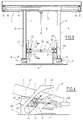
- Fig. 4 the course defined by the fixed track 22 is indicated by P', while P'' indicates the course defined by mobile track 43.
- F indicates the force applied to the slider means 30 by the tie rod 50.
- F' indicates the projection of F on the tangent to the course P', or on the course P' itself, given that in the part illustrated P' is rectilinear; the angle (a) defined between F and P' is smaller than 90°, as illustrated above.
- Angle (a) being smaller than 90°, the component F' of the force F is greater than zero and is basically directed upward, that is, it can supply the element 10 with a force that opposes the push that the weight of the person and the structure exert on the element 10.
- the slider means 30 rises along the track 22 and simultaneously moves along the track 43, nearing hinge 12. This produces the raising of the element 10 and thus the raising of the respective end of the upper frame 4. Conversely, increasing the length of the tie rod 50 achieves the inverse movements.
- each length of the tie rod 50 is a single position of slider means 30 along fixed track 22 and to this position corresponds a single geometric position (inclination) of mobile element 10.
- the geometric values of the fixed track and of the mobile track can be determined in such a way as to have a force F which is the most constant possible during the raising of structure 4.
- a force F which is the most constant possible during the raising of structure 4.
- the fixed track 22 with an inferior portion that is substantially rectilinear and inclined approximately 45° upward and toward the middle of the bed, an upper portion substantially horizontal and an intermediate arched portion that joins the upper portion to the lower portion.
- the force F necessary for balancing the weight sustained by the mobile element 10 is thus more or less constant; in particular, the load sustained by the bed when it is in the lowered position is advantageously exceeded; said position usually, in beds of this type, demands great effort from the motor means and thus requires high levels of power.
- the bed can be taken to the raised position equally well.
- the present invention makes it possible to create a bed that reaches the objects described in the preamble.
Landscapes
- Health & Medical Sciences (AREA)
- Life Sciences & Earth Sciences (AREA)
- Animal Behavior & Ethology (AREA)
- General Health & Medical Sciences (AREA)
- Public Health (AREA)
- Veterinary Medicine (AREA)
- Bearings For Parts Moving Linearly (AREA)
- Invalid Beds And Related Equipment (AREA)
- Orthopedics, Nursing, And Contraception (AREA)
- Mattresses And Other Support Structures For Chairs And Beds (AREA)
Applications Claiming Priority (2)
| Application Number | Priority Date | Filing Date | Title |
|---|---|---|---|
| IT04690290A IT1243531B (it) | 1990-12-04 | 1990-12-04 | Letto con piano di appoggio regolabile, in particolare per autoambulanze |
| IT4690290 | 1990-12-04 |
Publications (1)
| Publication Number | Publication Date |
|---|---|
| EP0489464A1 true EP0489464A1 (de) | 1992-06-10 |
Family
ID=11260412
Family Applications (1)
| Application Number | Title | Priority Date | Filing Date |
|---|---|---|---|
| EP91203120A Withdrawn EP0489464A1 (de) | 1990-12-04 | 1991-11-28 | Bett mit verstellbarer Liegefläche, insbesondere für Krankenwagen |
Country Status (3)
| Country | Link |
|---|---|
| EP (1) | EP0489464A1 (de) |
| IT (1) | IT1243531B (de) |
| YU (1) | YU188091A (de) |
Citations (5)
| Publication number | Priority date | Publication date | Assignee | Title |
|---|---|---|---|---|
| FR708088A (fr) * | 1930-03-27 | 1931-07-20 | Perfectionnements aux plate-formes élévatrices pour la visite et l'entretien des véhicules | |
| US2211474A (en) * | 1938-07-31 | 1940-08-13 | Elwa Elektro Ag | Lifting platform |
| CH286670A (de) * | 1950-10-06 | 1952-10-31 | Embru Werke Ag | Bett, insbesondere Krankenbett. |
| US4494259A (en) * | 1981-11-25 | 1985-01-22 | Simmons Universal Corporation | Adjustable bed |
| FR2651998A1 (fr) * | 1989-09-21 | 1991-03-22 | Heuliez Henri France Design | Table de support de brancard notamment destinee a l'equipement d'ambulances. |
-
1990
- 1990-12-04 IT IT04690290A patent/IT1243531B/it active IP Right Grant
-
1991
- 1991-11-28 EP EP91203120A patent/EP0489464A1/de not_active Withdrawn
- 1991-12-02 YU YU188091A patent/YU188091A/sh unknown
Patent Citations (5)
| Publication number | Priority date | Publication date | Assignee | Title |
|---|---|---|---|---|
| FR708088A (fr) * | 1930-03-27 | 1931-07-20 | Perfectionnements aux plate-formes élévatrices pour la visite et l'entretien des véhicules | |
| US2211474A (en) * | 1938-07-31 | 1940-08-13 | Elwa Elektro Ag | Lifting platform |
| CH286670A (de) * | 1950-10-06 | 1952-10-31 | Embru Werke Ag | Bett, insbesondere Krankenbett. |
| US4494259A (en) * | 1981-11-25 | 1985-01-22 | Simmons Universal Corporation | Adjustable bed |
| FR2651998A1 (fr) * | 1989-09-21 | 1991-03-22 | Heuliez Henri France Design | Table de support de brancard notamment destinee a l'equipement d'ambulances. |
Also Published As
| Publication number | Publication date |
|---|---|
| YU188091A (sh) | 1996-01-08 |
| IT1243531B (it) | 1994-06-16 |
| IT9046902A0 (it) | 1990-12-04 |
| IT9046902A1 (it) | 1992-06-05 |
Similar Documents
| Publication | Publication Date | Title |
|---|---|---|
| US10987268B2 (en) | Emergency cot with a litter height adjustment mechanism | |
| US5316432A (en) | Wheelchair lifts with automatic barrier | |
| US7458119B2 (en) | Bed having a chair egress position | |
| US5615431A (en) | Bed framework which is adjustable in elevation | |
| US3200416A (en) | Invalid bed | |
| EP1459722B1 (de) | Ein- und Aussteigevorrichtung für eine Sitzbank | |
| US4958979A (en) | Arrangement for a lift adapted to a motor vehicle | |
| US4407543A (en) | Mechanized wheelchair | |
| US4361917A (en) | Portable orthopedic bed | |
| KR20110018305A (ko) | 들것 및 환자 수송 시스템 | |
| US4384378A (en) | Mobile body lift | |
| EP1621171A1 (de) | Krankenhausbett | |
| US3983960A (en) | Scissors lift | |
| US4941799A (en) | Displaceable support for wheelchair | |
| CA2201536C (en) | Therapeutic table with gas spring assist lift for height adjustable table top | |
| US20010038787A1 (en) | Access ramp | |
| CN206621491U (zh) | 一种轮椅床的床架组件 | |
| US6729667B2 (en) | Stretcher suspension linkages | |
| US6494487B1 (en) | Stabilizing jack for recreational vehicles | |
| US3579671A (en) | Adjustable bed | |
| FI85685C (fi) | Lyftanordning foer motorfordon. | |
| EP0489464A1 (de) | Bett mit verstellbarer Liegefläche, insbesondere für Krankenwagen | |
| US3503083A (en) | Invalid's bed adjustable to sitting up position and having toilet facilities | |
| KR101901275B1 (ko) | 리프팅장치 | |
| EP0705091B1 (de) | Bett für intensivtherapie |
Legal Events
| Date | Code | Title | Description |
|---|---|---|---|
| PUAI | Public reference made under article 153(3) epc to a published international application that has entered the european phase |
Free format text: ORIGINAL CODE: 0009012 |
|
| AK | Designated contracting states |
Kind code of ref document: A1 Designated state(s): AT DE ES FR GB IT NL |
|
| 17P | Request for examination filed |
Effective date: 19921210 |
|
| 17Q | First examination report despatched |
Effective date: 19940802 |
|
| STAA | Information on the status of an ep patent application or granted ep patent |
Free format text: STATUS: THE APPLICATION IS DEEMED TO BE WITHDRAWN |
|
| 18D | Application deemed to be withdrawn |
Effective date: 19951128 |