EP0489613A1 - Gyroscope à entraînement par ressort, comportant un dispositif de débrayage - Google Patents
Gyroscope à entraînement par ressort, comportant un dispositif de débrayage Download PDFInfo
- Publication number
- EP0489613A1 EP0489613A1 EP91403121A EP91403121A EP0489613A1 EP 0489613 A1 EP0489613 A1 EP 0489613A1 EP 91403121 A EP91403121 A EP 91403121A EP 91403121 A EP91403121 A EP 91403121A EP 0489613 A1 EP0489613 A1 EP 0489613A1
- Authority
- EP
- European Patent Office
- Prior art keywords
- rotor
- shaft
- spring
- rotation
- coupling
- Prior art date
- Legal status (The legal status is an assumption and is not a legal conclusion. Google has not performed a legal analysis and makes no representation as to the accuracy of the status listed.)
- Granted
Links
Images


Classifications
-
- G—PHYSICS
- G01—MEASURING; TESTING
- G01C—MEASURING DISTANCES, LEVELS OR BEARINGS; SURVEYING; NAVIGATION; GYROSCOPIC INSTRUMENTS; PHOTOGRAMMETRY OR VIDEOGRAMMETRY
- G01C19/00—Gyroscopes; Turn-sensitive devices using vibrating masses; Turn-sensitive devices without moving masses; Measuring angular rate using gyroscopic effects
- G01C19/02—Rotary gyroscopes
- G01C19/025—Gyroscopes functioning for short periods
Definitions
- the present invention relates to a gyroscope whose rotation of the rotor is caused by a launching device using the rebound of a spring.
- Patent EP-A-0 235 475 already describes a gyroscope, of the type comprising a hollow rotor mounted on a fixed axis and containing a leaf spring wound on said shaft, a spring of which a first end is connected to this shaft by a permanent connection , while the other end is connected to the periphery of the rotor by a removable connection.
- the spring is banded by rotating the rotor, then held as such by a means for locking the rotor. When this means is removed, the rebound of the spring launches the rotor, then the second end of said spring uncouples from this rotor, thereby releasing the latter.
- Such a gyroscope has the drawback of requiring a first means of connecting the spring to the periphery of the shaft and a second means of connecting the spring to the rotor, this second means of connection having to be able to be released when the gyroscope has been launched. in rotation.
- the present invention aims to overcome these drawbacks and relates to a gyroscope with a leaf spring drive wound around a shaft, which has the particularity of not having a direct connection between this spring and this rotor, while ensuring, after launching in rotation of the rotor, an automatic uncoupling of this rotor from the spring-loaded launching device; this thus guarantees maximum energy transfer to the rotor, while providing a simple and safe declutching device.
- such a gyroscope does not require a removable attachment means between the spring and the shaft.
- such a gyroscope uses a rotor that does not have any attachment or connection means at the periphery, which makes it possible to obtain good balancing.
- the launching of the rotor being effected by the shaft, the latter passes, after launching, into a position distant from the rotor and remains there, which eliminates any risk of subsequent coupling between them.
- control means of the coupling means between the shaft and the rotor being the spring, this feature thus avoids the need to install additional means to perform this function.
- connection between the shaft and the rotor may include an angular reference
- said rotor and shaft may be coaxial, one comprising axially a part of said coupling means, and the other comprising axially the other part of said coupling means.
- said coupling means are of the screw-nut type or of the bayonet type.
- a translational locking means restricts the translational travel of said shaft, thus preventing any new coupling.
- the housing has a movable part fixedly connected to one end of the spring and making it possible to band the latter.
- the housing comprises a means for rotationally coupling said rotor with an external rotation drive system.
- This rotary coupling means can consist of a threaded hole, or a screw, arranged coaxially with the axis of the rotor.
- It can also be made up of the male or female part of a bayonet system.
- It can likewise be formed of a slot perpendicular to the axis of the rotor and passing through the latter, or else of a key arranged like said slot.
- the spring can be bandaged by an external means, which can be mechanical.
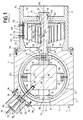
- Figure 1 shows the gyroscope in the state for which the spring is banded, the shaft and the rotor being coupled.
- FIG. 2 illustrates the state of the gyroscope for which the spring is released, the shaft and the rotor then being uncoupled.
- Figure 3 shows an example of coupling means between the rotor and the shaft.
- Figure 4 shows an example of other coupling means between the rotor and the shaft.
- the gyroscope according to the invention is shown, in Figure 1, in the state for which the spring is banded, the gyroscope then being ready to be launched. It comprises a housing 1 consisting of the fixed assembly of a first chassis 2 and a second chassis 3. The assembly generally has a symmetry of revolution with respect to an axis 4 passing through these two chassis.
- the first frame 2 has two end walls, respectively 5 and 6, perpendicular to the axis 4, and a side wall 7 joining these two walls and defining a cavity 8 of substantially spherical shape.
- the wall 6 has a first bearing 9 centered on the axis 4.
- a primary frame 10 comprising second and third bearings, respectively 11 and 12 , respectively close to the walls 5 and 6, and centered on the axis 4, which carry the respective ends 13 and 14 of a shaft 15 of a rotor 16.
- the bearing 12 is thus opposite the bearing 9.
- the end 14 of the shaft 15 has a threaded axial hole 19.
- a secondary frame 20 is articulated on the primary frame 10, facing the periphery of the rotor 16, thanks to two collinear axes 21 and 22.
- the assembly consisting of the cavity 8, the primary frame 10, the secondary frame 20, the shaft 15 and the rotor 16, has symmetry with respect to a plane 23 perpendicular to the axis 4 and equidistant from the two bearings 11 and 12.
- the plane 23 intersects this axis 4 at a point 24, center of the sphere defined by the primary frame 10.
- Said axes 21 and 22 are located in the plane 23 and their axis passes through the center 24 .
- the chassis 2 comprises a flat 30 located on the external edge common to the walls 5 and 7, and having a passage 31 in its center, oriented towards the center 24 of the sphere.
- On this flat are mounted locking means 32 consisting of a housing 33, fixed to the frame 2 by fixing screws 34, and in which a movable finger 35, oriented towards the center 24 of the sphere, can slide on passing through the passage 31, as well as through a hole 36, drilled in the primary frame 10 along an axis passing through the center 24 and the passage 31.
- This finger 35 is terminated, side opposite to the center 24, by a piston 37 sliding inside the housing 33.
- the piston 37 has, at its periphery, an elastic split ring housed in a circular groove, while the internal cylindrical wall of the housing 33 has, near its end opposite to the flat 30, a circular groove capable of receiving the ring when the piston 37 goes into its second position.
- This finger 35 can occupy either a first position, for which it passes through the hole 36 of the primary frame 10 and comes into a hole 38 located at the periphery of the rotor 16, or a second position, for which it is outside the frame primary 10.
- Control means 39 pyrotechnic (not shown) allows this finger 35 to pass from its first to its second position
- control means 40 consisting of an opening in the housing 33, in the axis of the movable finger 35, and a threaded rod 41 which can be screwed into the piston 37, allows the passage from one to the other position, by pushing or pulling.
- the second chassis 3 of generally cylindrical shape centered on the axis 4, has an external radius close to the radius of the spherical cavity 8 of the first chassis 2.
- a first end wall 50 opposite the first chassis 2 and perpendicular to the axis 4, carries a fourth bearing 51, while a second end wall of the cylinder is open, and has a shoulder of revolution 52, received in a recess 53 in the wall 6 of the first frame 2, and which can be fixed by fixing screws 54 to said wall 6.
- These two end walls 50 and 52 are connected by a wall with a cylindrical surface 55.
- a second rotary shaft 56 centered on the axis 4, has its ends 57 and 58 carried respectively by the bearings 9 and 51.
- the end 57 has a cylindrical shaft end forming a screw 59, projecting from the bearing 9, having approximately the size of the hole 19, and which can be screwed into it, according to a first direction of rotation, for example clockwise when the gyroscope is observed from a point on the axis 4 located on the side of the wall 50.
- the shaft 56 comprises, starting from its end 57, a flourishing 60, followed by a groove 61, of diameter a little less than the inside diameter of the bearing 51, and extending over an axial length of size close to that of said bearing 51; this groove is followed by a cylindrical surface 62 of diameter equal to the internal diameter of the bearing 51, apart from play, and of axial length substantially equal to that of the bearing 51.
- a means of locking in translation 63 produced in the form of a spontaneously expandable elastic split ring, of external diameter, in the absence of stress, greater than the internal diameter of the bearing 51, is mounted in the groove 61; this ring has a thickness equal to the difference between the radius of the groove and that of the internal wall of the bearing 51.
- the shaft 56 can thus, depending on the position of the above elements, have an axial displacement.
- the second shaft 56 has a flat 64 having in the center a threaded radial hole 65 receiving a fixing screw 66 used to fix a first end 67 of a leaf spring 68, a second end 69 of which is fixed to a internal face 70 of the wall 55 of the chassis 3, by two fixing screws 71 fixed in attachment points 72 consisting of holes drilled in said cylindrical wall, said spring 68 being wound around the shaft 56, in said first direction of rotation from this shaft 56.
- the plate 64 is intended to compensate for the height of the head of the fixing screw 66, so that it does not interfere with the turns of the spring 68.
- the spring 68 In the unloaded state, the spring 68 is contained in a cylindrical volume, centered on the axis 4, of diameter substantially equal to that of the internal cavity of the chassis 3, and of width equal to the width of the leaf of the spring 68, volume limited by the two edges of the turns which are respectively in the same plane on either side of the spring. Conversely, when the shafts 15 and 56 are coupled, the spring 68 is axially deformed and the edges of the turns are then offset axially between them. In this state, the screw 59 is screwed into the hole 19, and the groove 61 is engaged under the bearing 51, which is also in contact with the surface 62 of the shaft 56.
- FIG. 2 illustrates the deactivated state of the gyroscope launching device, that is to say when the shafts 15 and 56 are uncoupled.
- the chassis 3 may comprise, or be made up of a rotary part 75 centered on the axis 4, carrying the attachment points 72 for the spring.
- This rotary part 75 rotates while resting on the symmetrically rotated shoulder formed by the recess 53, a rotation lock being ensured by the fixing screws 54.
- a ratchet device (not shown) can be installed at the recess 53.
- the gyroscope is launched in rotation as follows.
- the finger 35 is put, or maintained, in its first position by means of the control 40, which blocks the rotor 16.
- the spring 68 is then bandaged by rotating the rotary part 75 in the first direction of rotation, then blocking it by the fixing screws 54.
- Another way of banding the spring 68 consists, as before, in blocking the rotation of the rotor 16 and in coupling the shafts 15 and 56 therebetween.
- the rotary part 75 is blocked by the fixing screws 54 then the rotor 16 is released in rotation by pulling on the rod 41 previously screwed into the piston 37.
- a crank ended by a male part penetrating into the groove 18 then makes it possible to bandage the spring 68, turning in the opposite direction to the first direction.
- the rotor 16 is then locked in rotation by means of the rod 41 which passes the locking means 32 of the rotation of the rotor 16 into their first position, which is done by pressing the finger 35 into the hole 38 of this rotor 16 , by means of the rod 41.
- the rotor 16 and its shaft 15 can then be rotated, which is done by passing the finger 35 from its first position, which blocks the rotor 16, to its second position, which releases the latter, under the effect of the control 39, produced in the form of an overpressure in the housing 33, obtained by the explosion of a low pyrotechnic charge, which, bearing on the flat 30, pushes the piston 37 and the associated finger 35 towards the outside the primary frame 10.
- the elastic split ring surrounding the piston 37 then expands in the groove of the internal wall of the housing 33 and prevents any return of the piston 37 to its first position.
- the spring 68 is then free to unwind and it drives the two shafts 15 and 56 and the rotor 16 in the first direction of rotation, which confirms the screwing of said shafts.
- This second shaft 56 has a translational rest position which corresponds to the state in which the spring 68 is not axially deformed.
- the uncoupling of this second shaft 56 with respect to the first shaft 15 allows the spring 68 to return, under the action of the axial restoring forces generated by its axial elastic deformation, to its position of rest in translation.
- the shaft 56, deviating from the shaft 15, thus passes through its position of rest in translation, which brings out the split ring 63 from the inside of the bearing 51.
- This second shaft 56 tends to protrude, still in the direction moving it away from the first shaft 15, its rest position in translation of a length substantially equal to its axial deformation when it has finished uncoupling, that is to say the translation which corresponds to the coupling of the first thread of the screw 59 to the hole 19.
- the possible natural oscillatory movement in translation of this shaft 56 is blocked by the ring 63 which prevents it from exceeding its rest position when it returns to the shaft 15.
- the oscillation of the shaft 56 is thus quickly damped by successive percussions of the ring 63 on the side of the bearing 51, and the two shafts can no longer couple.
- the spring 68 thus constitutes an automatic control means for the disconnection of the coupling means 19 and 59.
- Such a device thus makes it possible to ensure the launching in rotation of a gyroscope while guaranteeing a disengagement of the spring-loaded launching device, at the desired moment, and by means of a simple and robust mechanism.
- the second shaft 56 can be used to launch two rotors contained in two respective chassis 2, and located on either side of the second shaft 56.
- Figure 3 shows an exemplary embodiment to extend the latter on the side of its end 58 and to end it with a conical end 80, for example, carrying radial ribs.
- a third shaft 81 relating to a second rotor, comprises, at the end, a chamber 82 receiving said conical end 80, through an opening 83 of an end wall 84, the cutting of said opening 83 reproducing in hollow the shape of the conical end 80.
- the corresponding shapes of the end 80 and the opening 83 are axially spaced from the axial distance along which the screw 59 translates when it comes screw fully into hole 19.
- the initial assembly can be done by passing the male shaft, which has one conical end, through the other.
- This conical shape can obviously have its inclination modified to a "T" shape, with ribs in a plane perpendicular to the axis 4, or vice versa, to a cylindrical shape, the ribs being parallel to the axis 4 and extending only over the desired length.
- a screw coupling of the third shaft 82 is still possible but not necessary, since the shaft 15 ensures the translational locking of the second shaft 56. It is thus possible to have a type 18 groove, integral with one of said shafts, capable of receiving a key, secured to the other shaft, which acts as a screwdriver.
- the male shaft 56 can serve as a sliding bearing for the other shaft 81, either at the level of the central body of the male shaft itself, or at the periphery of the conical part 80, then extended and carrying a such a bearing, as shown in dotted lines in FIG. 3, carrying the inner face of the chamber 82, this second solution making it possible to have a larger diameter for making the bearing.
- FIG. 4 represents other means of coupling between the shaft 15 and the shaft 56, in the form of a bayonet device.
- the shaft 15 has at the end a hole 90, the cylindrical wall of which is pierced with two diametrically opposite notches 91 and rotating in the first direction of rotation when one penetrates into this hole 90.
- the shaft 56 comprises a cylindrical male part 92 provided with two diametrically opposite lugs 93, which can penetrate into said notches 91 and come to bear respectively on a shoulder at the bottom of these notches 91 when this male part is screwed into said hole 90.
- the surface of the shoulders is provided with a size sufficient to withstand the force exerted by the spring 68.
Landscapes
- Physics & Mathematics (AREA)
- Engineering & Computer Science (AREA)
- General Physics & Mathematics (AREA)
- Radar, Positioning & Navigation (AREA)
- Remote Sensing (AREA)
- Transmission Devices (AREA)
- Gyroscopes (AREA)
- Springs (AREA)
Abstract
Description
- La présente invention concerne un gyroscope dont la rotation du rotor est provoquée par un dispositif de lancement utilisant la détente d'un ressort.
- Le brevet EP-A- 0 235 475 décrit déjà un gyroscope, du type comprenant un rotor creux monté sur un axe fixe et contenant un ressort à lame enroulé sur ledit arbre, ressort dont une première extrémité est reliée à cet arbre par une liaison permanente, tandis que l'autre extrémité est reliée au pourtour du rotor par une liaison amovible. Le ressort est bandé en faisant tourner le rotor, puis maintenu tel par un moyen de blocage du rotor. Lorsque ce moyen est enlevé, la détente du ressort lance le rotor, puis la seconde extrémité dudit ressort se désaccouple de ce rotor, libérant ainsi ce dernier.
- Un tel gyroscope présente l'inconvénient de nécessiter un premier moyen de liaison du ressort sur la périphérie de l'arbre et un second moyen de liaison du ressort avec le rotor, ce deuxième moyen de liaison devant pouvoir se libérer lorsque le gyroscope a été lancé en rotation.
- Ceci nécessite un mécanisme délicat d'attache, avec des formes spécifiques pour l'extrémité du ressort et pour le point d'attache tenant cette extrémité. Cela peut aussi induire des contraintes mécaniques dans les extrémités du ressort, qui peuvent casser.
- Par ailleurs, ces points d'attache détruisent la symétrie de révolution des pièces concernées et en particulier sont défavorables à l'équilibrage du rotor.
- La présente invention a pour but de pallier ces inconvénients et concerne un gyroscope à entraînement par ressort à lame enroulé autour d'un arbre, qui présente la particularité de ne pas comporter de liaison directe entre ce ressort et ce rotor, tout en assurant, après lancement en rotation du rotor, un désaccouplement automatique de ce rotor vis-à-vis du dispositif de lancement à ressort; ceci permet ainsi de garantir un transfert maximum d'énergie vers le rotor, tout en offrant un dispositif de débrayage simple et sûr.
- A cet effet, le gyroscope selon l'invention, du type comprenant:
- un boîtier;
- un rotor disposé dans ledit boîtier;
- un ressort à lame spiralé susceptible de passer de l'état bandé à l'état débandé pour lancer en rotation ledit rotor et dont l'une des extrémités est liée audit boîtier;
- des moyens de blocage de la rotation dudit rotor;
- des moyens de commande des moyens de blocage de la rotation dudit rotor;
est remarquable en ce qu'il comporte: - un arbre rotatif disposé coaxialement audit ressort et susceptible d'être déplacé en translation, l'autre extrémité dudit ressort étant liée audit arbre, et
- des moyens d'accouplement coopérants entre ledit arbre et ledit rotor, le désaccouplement dudit arbre audit rotor étant commandé par ledit ressort, lorsque celui-ci atteint son état débandé.
- Ainsi, un tel gyroscope ne nécessite pas de moyen d'attache amovible entre le ressort et l'arbre.
- De plus, le ressort n'étant pas fixé sur le rotor, le risque d'accrochage ou de frottement entre ce ressort et le rotor, après lancement de ce dernier, n'existe pas.
- Par ailleurs, un tel gyroscope utilise un rotor ne comportant pas de moyen d'attache ou de liaison en périphérie, ce qui permet d'obtenir un bon équilibrage.
- De même, le lancement du rotor s'effectuant par l'arbre, celui-ci passe, après lancement, dans une position éloignée du rotor et y reste, ce qui supprime tout risque de couplage ultérieur entre-eux.
- De plus, le moyen de commande des moyens d'accouplement entre l'arbre et le rotor étant le ressort, cette particularité évite ainsi la nécessité d'implanter un moyen supplémentaire pour réaliser cette fonction.
- Bien que le raccordement entre l'arbre et le rotor puisse comporter un renvoi angulaire, lesdits rotor et arbre peuvent être coaxiaux, l'un comportant axialement une partie desdits moyens d'accouplement, et l'autre comportant axialement l'autre partie desdits moyens d'accouplement.
- Par exemple, lesdits moyens d'accouplement sont du type vis-écrou ou du type à baïonnette.
- Cela constitue ainsi des moyens d'accouplement très simples entre l'arbre et le rotor, sans dispositif de renvoi angulaire, et le désaccouplement peut s'effectuer par translation selon l'axe commun.
- De plus, après désaccouplement des moyens d'accouplement du rotor et de l'arbre, un moyen de blocage en translation restreint la course de translation dudit arbre, empêchant ainsi tout nouveau couplage.
- De ce fait, tout frottement ultérieur au niveau des moyens d'accouplement est impossible après la fin du lancement du rotor.
- Par ailleurs, le boîtier comporte une partie mobile reliée de façon fixe à une extrémité du ressort et permettant de bander ce dernier.
- Cela permet ainsi de bander aisément ce ressort en l'absence de moyen externe.
- De plus, le boîtier comporte un moyen d'accouplement en rotation dudit rotor avec un système externe d'entraînement en rotation. Ce moyen d'accouplement en rotation peut être constitué d'un trou fileté, ou d'une vis, disposé coaxialement avec l'axe du rotor.
- Il peut aussi être constitué de la partie mâle ou femelle d'un système à baïonnette.
- Il peut de même être formé d'une fente perpendiculaire à l'axe du rotor et passant par celui-ci, ou bien d'une clavette disposée comme ladite fente.
- Ainsi, le ressort peut être bandé par un moyen externe, pouvant être mécanique.
- Les figures du dessin annexé feront bien comprendre comment l'invention peut être réalisée. Sur ces figures, des références identiques désignent des éléments identiques ou semblables.
- La figure 1 représente le gyroscope dans l'état pour lequel le ressort est bandé, l'arbre et le rotor étant accouplés.
- La figure 2 illustre l'état du gyroscope pour lequel le ressort est débandé, l'arbre et le rotor étant alors désaccouplés.
- La figure 3 montre un exemple de moyens d'accouplement entre le rotor et l'arbre.
- La figure 4 montre un exemple d'autres moyens d'accouplement entre le rotor et l'arbre.
- Le gyroscope selon l'invention est représenté, sur la figure 1, à l'état pour lequel le ressort est bandé, le gyroscope étant alors prêt à être lancé. Il comporte un boîtier 1 constitué de l'assemblage fixe d'un premier châssis 2 et d'un second châssis 3. L'ensemble présente globalement une symétrie de révolution par rapport à un axe 4 traversant ces deux châssis.
- Le premier châssis 2 comporte deux parois d'extrémité, respectivement 5 et 6, perpendiculaires à l'axe 4, et une paroi latérale 7 joignant ces deux parois et définissant une cavité 8 de forme sensiblement sphérique. La paroi 6 comporte un premier palier 9 axé sur l'axe 4. A l'intérieur et à proximité de la face interne de ce premier châssis 2, se trouve un cadre primaire 10, comportant des deuxième et troisième paliers, respectivement 11 et 12, proches respectivement des parois 5 et 6, et axés sur l'axe 4, qui portent les extrémités respectives 13 et 14 d'un arbre 15 d'un rotor 16. Le palier 12 est ainsi en regard du palier 9. Ces paliers 11 et 12 assurent aussi le blocage en translation axiale de cet arbre. Une ouverture 17, située dans la paroi 5, en regard de l'extrémité 13 de l'arbre 15, permet d'accéder à une rainure 18 située en bout de cet arbre 15 sur cette extrémité 13, perpendiculaire à l'axe 4 et passant par celui-ci. L'extrémité 14 de l'arbre 15 comporte un trou axial fileté 19. Un cadre secondaire 20 est articulé sur le cadre primaire 10, en regard de la périphérie du rotor 16, grâce à deux axes colinéaires 21 et 22.
- L'ensemble constitué de la cavité 8, du cadre primaire 10, du cadre secondaire 20, de l'arbre 15 et du rotor 16, présente une symétrie par rapport à un plan 23 perpendiculaire à l'axe 4 et équidistant des deux paliers 11 et 12. Le plan 23 coupe cet axe 4 en un point 24, centre de la sphère définie par le cadre primaire 10. Lesdits axes 21 et 22 sont situés dans le plan 23 et leur axe passe par le centre 24.
- Le châssis 2 comporte un méplat 30 situé sur l'arête externe commune aux parois 5 et 7, et ayant un passage 31 en son centre, orienté vers le centre 24 de la sphère. Sur ce méplat sont montés des moyens de blocage 32 constitués d'un boîtier 33, fixé au châssis 2 par des vis de fixation 34, et dans lequel un doigt mobile 35, orienté vers le centre 24 de la sphère, peut coulisser en passant au travers du passage 31, ainsi qu'au travers d'un trou 36, percé dans le cadre primaire 10 selon un axe passant par le centre 24 et le passage 31. Ce doigt 35 est terminé, côté opposé au centre 24, par un piston 37 coulissant à l'intérieur du boîtier 33.
- Le piston 37 comporte, à sa périphérie, une bague fendue élastique logée dans une gorge circulaire, tandis que la paroi cylindrique interne du boîtier 33 comporte, près de son extrémité opposée au méplat 30, une gorge circulaire pouvant recevoir la bague lorsque le piston 37 passe dans sa seconde position.
- Ce doigt 35 peut occuper soit une première position, pour laquelle il traverse le trou 36 du cadre primaire 10 et vient pénétrer dans un trou 38 situé en périphérie du rotor 16, soit une seconde position, pour laquelle il est à l'extérieur du cadre primaire 10. Un moyen de commande 39, pyrotechnique (non représenté), permet de faire passer ce doigt 35 de sa première à sa seconde position, tandis qu'un moyen de commande 40, constitué d'une ouverture dans le boîtier 33, dans l'axe du doigt mobile 35, et d'une tige filetée 41 pouvant se visser dans le piston 37, permet le passage de l'une à l'autre position, par poussée ou traction.
- Le second châssis 3, de forme générale cylindrique axée sur l'axe 4, a un rayon externe voisin du rayon de la cavité sphérique 8 du premier châssis 2. Une première paroi d'extrémité 50, opposée au premier châssis 2 et perpendiculaire à l'axe 4, porte un quatrième palier 51, tandis qu'une seconde paroi d'extrémité du cylindre est ouverte, et comporte un épaulement de révolution 52, reçu dans un évidement 53 de la paroi 6 du premier châssis 2, et pouvant être fixé par des vis de fixation 54 à ladite paroi 6. Ces deux parois d'extrémité 50 et 52 sont reliées par une paroi à surface cylindrique 55.
- Un second arbre rotatif 56, axé sur l'axe 4, a ses extrémités 57 et 58 portées respectivement par les paliers 9 et 51. L'extrémité 57 comporte un bout d'arbre cylindrique formant vis 59, débordant du palier 9, ayant approximativement la taille du trou 19, et pouvant s'y visser, selon un premier sens de rotation, par exemple le sens horaire lorsqu'on observe le gyroscope à partir d'un point de l'axe 4 situé du côté de la paroi 50.
- L'arbre 56 comporte, en partant de son extrémité 57, un épanouissement 60, suivi d'une gorge 61, de diamètre un peu inférieur au diamètre intérieur du palier 51, et s'étendant sur une longueur axiale de taille voisine de celle dudit palier 51; cette gorge est suivie d'une surface cylindrique 62 de diamètre égal au diamètre interne du palier 51, au jeu près, et de longueur axiale sensiblement égale à celle du palier 51. Un moyen de blocage en translation 63, réalisé sous la forme d'une bague fendue élastique spontanément expansible, de diamètre externe, en l'absence de contrainte, supérieur au diamètre interne du palier 51, est monté dans la gorge 61; cette bague a une épaisseur égale à la différence entre le rayon de la gorge et celui de la paroi interne du palier 51. L'arbre 56 peut ainsi, selon la position des éléments ci-dessus, avoir un déplacement axial.
- Dans sa partie médiane, le second arbre 56 présente un plat 64 comportant au centre un trou radial fileté 65 recevant une vis de fixation 66 servant à fixer une première extrémité 67 d'un ressort à lame 68 dont une seconde extrémité 69 est fixée sur une face interne 70 de la paroi 55 du châssis 3, par deux vis de fixation 71 fixées dans des points d'attache 72 constitués de trous percés dans ladite paroi cylindrique, ledit ressort 68 étant enroulé autour de l'arbre 56, selon ledit premier sens de rotation en partant de cet arbre 56. Le plat 64 est destiné à compenser la hauteur de la tête de la vis de fixation 66, de façon qu'elle ne gêne pas les spires du ressort 68. A l'état débandé, le ressort 68 est contenu dans un volume cylindrique, axé sur l'axe 4, de diamètre sensiblement égal à celui de la cavité interne du châssis 3, et de largeur égale à la largeur de la lame du ressort 68, volume limité par les deux bords des spires qui sont respectivement dans un même plan de part et d'autre du ressort. Inversement, lorsque les arbres 15 et 56 sont accouplés, le ressort 68 est déformé axialement et les bords des spires sont alors décalés axialement entre eux. Dans cet état, la vis 59 est vissée dans le trou 19, et la gorge 61 se trouve engagée sous le palier 51, qui est aussi au contact de la surface 62 de l'arbre 56.
- La figure 2 illustre l'état désactivé du dispositif de lancement du gyroscope, c'est-à-dire lorsque les arbres 15 et 56 sont désaccouplés.
- Pour faciliter le bandage du ressort 68, le châssis 3 peut comporter, ou être constitué d'une partie rotative 75 axée sur l'axe 4, portant les points d'attache 72 pour le ressort. Cette partie rotative 75 tourne en prenant appui sur l'épaulement à symétrie de révolution constitué de l'évidement 53, un blocage en rotation étant assuré par les vis de fixation 54. Un dispositif à cliquets (non représenté) peut être implanté au niveau de l'évidement 53.
- Le lancement en rotation du gyroscope est effectué de la manière suivante.
- Tout d'abord, le doigt 35 est mis, ou maintenu, dans sa première position au moyen de la commande 40, ce qui bloque le rotor 16.
- Ensuite, on va accoupler les deux arbres 15 et 56 par vissage de la vis 59 dans le trou 19. Cela nécessite de libérer préalablement la course en translation du second arbre 56, ce qui s'effectue en pinçant radialement la bague 63 de façon à la faire pénétrer à l'intérieur du palier 51 en poussant sur l'épanouissement 60. Le ressort 68 est ainsi contraint à se déformer axialement de façon élastique, les bords des spires se décalant axialement entre eux, comme représenté à la figure 1. Au moyen de l'épanouissement 60, on peut alors visser la vis 59 dans le trou 19. Le rotor 16 et le second arbre 56 sont ainsi solidaires du ressort 68.
- Le ressort 68 est ensuite bandé en faisant tourner dans le premier sens de rotation la partie rotative 75, puis en la bloquant par les vis de fixation 54.
- Une autre façon de bander le ressort 68 consiste, comme précédemment, à bloquer la rotation du rotor 16 et à accoupler les arbres 15 et 56 entre-eux.
- La partie rotative 75 est bloquée par les vis de fixation 54 puis le rotor 16 est débloqué en rotation en tirant sur la tige 41 préalablement vissée dans le piston 37. Une manivelle terminée par une partie mâle pénétrant dans la rainure 18 permet alors de bander le ressort 68, en tournant dans le sens opposé au premier sens. Le rotor 16 est ensuite bloqué en rotation au moyen de la tige 41 qui fait passer les moyens de blocage 32 de la rotation du rotor 16 dans leur première position, ce qui est effectué en enfonçant le doigt 35 dans le trou 38 de ce rotor 16, au moyen de la tige 41.
- Le rotor 16 et son arbre 15 peuvent alors être lancés en rotation, ce qui s'effectue en faisant passer le doigt 35 de sa première position, qui bloque le rotor 16, à sa seconde position, qui libère ce dernier, sous l'effet de la commande 39, réalisée sous la forme d'une surpression dans le boîtier 33, obtenue par l'explosion d'une faible charge pyrotechnique, qui, prenant appui sur le méplat 30, repousse le piston 37 et le doigt 35 associé vers l'extérieur du cadre primaire 10.
- La bague fendue élastique entourant le piston 37 se détend alors dans la rainure de la paroi interne du boîtier 33 et empêche tout retour du piston 37 vers sa première position.
- Le ressort 68 est alors libre de se débander et il entraîne les deux arbres 15 et 56 et le rotor 16 dans le premier sens de rotation, ce qui confirme le vissage desdits arbres.
- Lorsque le ressort 68 a transféré la quasi-totalité de son énergie stockée, il se trouve débandé et tend à freiner le second arbre 56 dans sa rotation, alors que le premier arbre 15 continue de tourner à vitesse quasi-constante sous l'effet de l'inertie du rotor 16. De ce fait, la différence de vitesse angulaire entre ces deux arbres fait se dévisser la vis 59 du trou 19, libérant ainsi l'accouplement de ces deux arbres. Le second arbre 56, qui reste lié au ressort 68, a sa vitesse de rotation qui diminue et s'annule puis s'inverse, pour ensuite osciller autour de la position de repos en rotation du ressort 68, représentée à la figure 2.
- Ce second arbre 56 a une position de repos en translation qui correspond à l'état pour lequel le ressort 68 n'est pas déformé axialement. Le désaccouplement de ce second arbre 56 vis-à-vis du premier arbre 15 autorise le ressort 68 à revenir, sous l'action des forces de rappel axiales engendrées par sa déformation élastique axiale, vers sa position de repos en translation. L'arbre 56, s'écartant de l'arbre 15, passe ainsi par sa position de repos en translation, ce qui fait sortir la bague fendue 63 de l'intérieur du palier 51. Ce second arbre 56 tend à dépasser, toujours dans la direction l'écartant du premier arbre 15, sa position de repos en translation d'une longueur sensiblement égale à sa déformation axiale au moment où il a terminé de se désaccoupler, c'est-à-dire la translation qui correspond à l'accouplement du premier filet de la vis 59 au trou 19. Cependant, l'éventuel mouvement naturel oscillatoire en translation de cet arbre 56 est bloqué par la bague 63 qui l'empêche de dépasser sa position de repos lors de son retour vers l'arbre 15. L'oscillation de l'arbre 56 est ainsi amortie rapidement par des percussions successives de la bague 63 sur le flanc du palier 51, et les deux arbres ne peuvent plus se coupler. Le ressort 68 constitue ainsi un moyen de commande automatique de la déconnexion des moyens d'accouplement 19 et 59.
- Un tel dispositif permet ainsi d'assurer le lancement en rotation d'un gyroscope tout en garantissant un débrayage du dispositif de lancement à ressort, à l'instant voulu, et au moyen d'un mécanisme simple et robuste.
- On remarquera que le second arbre 56 peut être utilisé pour lancer deux rotors contenus dans deux châssis 2 respectifs, et situés de part et d'autre du second arbre 56. La figure 3 montre un exemple de réalisation pour prolonger ce dernier du côté de son extrémité 58 et de le terminer par une extrémité conique 80, par exemple, portant des nervures radiales. Un troisième arbre 81, relatif à un second rotor, comporte, en extrémité, une chambre 82 recevant ladite extrémité conique 80, au travers d'une ouverture 83 d'une paroi d'extrémité 84, la découpe de ladite ouverture 83 reproduisant en creux la forme de l'extrémité conique 80. A l'état repos du ressort 68, les formes correspondantes de l'extrémité 80 et l'ouverture 83 sont espacées axialement de la distance axiale selon laquelle se translate la vis 59 lorsqu'elle vient se visser à fond dans le trou 19. Le montage initial peut se faire en passant l'arbre mâle, qui a une extrémité conique, au travers de l'autre. Cette forme conique peut évidemment voir son inclinaison être modifiée jusqu'à une forme en "T", à nervures dans un plan perpendiculaire à l'axe 4, ou inversement, jusqu'à une forme cylindrique, les nervures étant parallèles à l'axe 4 et ne s'étendant que sur la longueur voulue.
- Un couplage par vissage du troisième arbre 82 est encore possible mais non nécessaire, puisque l'arbre 15 assure le blocage en translation du second arbre 56. On peut ainsi avoir une rainure du type 18, solidaire de l'un desdits arbres, pouvant recevoir une clavette, solidaire de l'autre arbre, qui fait office de tournevis.
- L'arbre mâle 56 peut servir de porte-palier glissant pour l'autre arbre 81, soit au niveau du corps central de l'arbre mâle lui-même, soit au niveau du pourtour de la partie conique 80, prolongée alors et portant un tel palier, comme représenté en pointillé à la figure 3, portant la face intérieure de la chambre 82, cette deuxième solution permettant de disposer d'un diamètre plus grand pour réaliser le palier.
- La figure 4 représente d'autres moyens d'accouplement entre l'arbre 15 et l'arbre 56, sous la forme d'un dispositif à baïonnette. L'arbre 15 comporte en extrémité un trou 90 dont la paroi cylindrique est percée de deux échancrures 91 diamétralement opposées et tournant dans le premier sens de rotation lorsque l'on pénètre dans ce trou 90. De son côté, l'arbre 56 comporte une partie mâle cylindrique 92 pourvue de deux ergots 93 diamétralement opposés, qui peuvent pénétrer dans lesdites échancrures 91 et venir respectivement prendre appui sur un épaulement au fond de ces échancrures 91 lorsqu'on visse cette partie mâle dans ledit trou 90. La surface des épaulements est prévue de taille suffisante pour supporter la force exercée par le ressort 68.
Claims (10)
- Gyroscope, du type comprenant :- un boîtier (1) ;- un rotor (16) disposé dans ledit boîtier (1) ;- un ressort à lame spiralée (68) susceptible de passer de l'état bande à l'état débandé pour lancer en rotation ledit rotor (16) et dont l'une des extrémités (69) est liée audit boîtier (1) ;- des moyens de blocage (32) de la rotation dudit rotor (16) ;- des moyens de commande (39) des moyens de blocage (32) de la rotation dudit rotor (16) ;- un arbre (56) rotatif dispose coaxialement audit ressort (68) et susceptible d'être déplacé en translation, l'autre extrémité (67) dudit ressort (68) étant liée audit arbre (56) ;- des moyens d'accouplement (19,59) dudit arbre (56) avec ledit rotor (16) susceptibles de solidariser en rotation ledit arbre et ledit rotor ;
caractérisé en ce que lesdits moyens d'accouplement (19,59) sont de plus aptes à solidariser en translation ledit arbre (56) et ledit rotor (16), et en ce que ledit ressort (68) commande à lui seul le désaccouplement, en rotation et en translation, dudit arbre (56) et dudit rotor (16) lorsqu'il passe de l'état bande à l'état débandé. - Gyroscope selon la revendication 1, caractérisé en ce que lesdits rotor (16) et arbre (56) sont coaxiaux, et en ce que l'un comporte axialement l'un desdits moyens d'accouplement, et que l'autre comporte axialement l'autre desdits moyens d'accouplement.
- Gyroscope selon la revendication 1 ou 2, caractérisé en ce que lesdits moyens d'accouplement entre le rotor (16) et l'arbre (56) sont du type vis-écrou.
- Gyroscope selon la revendication 1 ou 2, caractérisé en ce que lesdits moyens d'accouplement entre le rotor (16) et l'arbre (56) sont du type à baïonnette.
- Gyroscope selon l'une quelconque des revendications précédentes, caractérisé en ce qu'un moyen de blocage en translation (63) limite, après désaccouplement des moyens d'accouplement (19,59) du rotor (16) et de l'arbre (56), la course de translation dudit arbre (56), empêchant ainsi tout nouveau couplage.
- Gyroscope selon la revendication 5, caractérisé en ce que le moyen de blocage en translation de l'arbre (56) est une bague élastique (63).
- Gyroscope selon l'une quelconque des revendications précédentes, caractérisé en ce que le boîtier (1) comporte une partie mobile (75) reliée de façon fixe à une extrémité (69) du ressort (68) et permettant de bander ce dernier.
- Gyroscope selon l'une quelconque des revendications précédentes, caractérisé en ce que le rotor (16) comporte, en extrémité (13) de son arbre (15), un moyen d'accouplement en rotation, constitué d'une vis ou d'un trou fileté.
- Gyroscope selon l'une quelconque des revendications 1 à 7, caractérisé en ce que le rotor (16) comporte, en extrémité (13) de son arbre (15), un moyen d'accouplement en rotation, constitué de la partie mâle ou de la partie femelle d'un système à baïonnette.
- Gyroscope selon l'une quelconque des revendications 1 à 7, caractérisé en ce que le rotor (16) comporte, en extrémité (13) de son arbre (15), un moyen d'accouplement en rotation, constitué d'une fente (18) ou d'une clavette.
Applications Claiming Priority (2)
| Application Number | Priority Date | Filing Date | Title |
|---|---|---|---|
| FR9015309 | 1990-12-06 | ||
| FR9015309A FR2670284B1 (fr) | 1990-12-06 | 1990-12-06 | Gyroscope a entrainement par ressort, comportant un dispositif de debrayage. |
Publications (2)
| Publication Number | Publication Date |
|---|---|
| EP0489613A1 true EP0489613A1 (fr) | 1992-06-10 |
| EP0489613B1 EP0489613B1 (fr) | 1994-09-21 |
Family
ID=9402977
Family Applications (1)
| Application Number | Title | Priority Date | Filing Date |
|---|---|---|---|
| EP19910403121 Expired - Lifetime EP0489613B1 (fr) | 1990-12-06 | 1991-11-20 | Gyroscope à entraînement par ressort, comportant un dispositif de débrayage |
Country Status (4)
| Country | Link |
|---|---|
| EP (1) | EP0489613B1 (fr) |
| DE (1) | DE69104171T2 (fr) |
| ES (1) | ES2064064T3 (fr) |
| FR (1) | FR2670284B1 (fr) |
Cited By (8)
| Publication number | Priority date | Publication date | Assignee | Title |
|---|---|---|---|---|
| EP0706029A1 (fr) | 1994-10-05 | 1996-04-10 | Aerospatiale Societe Nationale Industrielle | Système gyroscopique pour missile en autorotation |
| RU2176779C1 (ru) * | 2000-05-22 | 2001-12-10 | Государственное унитарное предприятие "Конструкторское бюро приборостроения" | Гироскопический прибор |
| RU2179302C1 (ru) * | 2000-06-26 | 2002-02-10 | Государственное унитарное предприятие "Конструкторское бюро приборостроения" | Гироскопический прибор |
| RU2180728C2 (ru) * | 1999-11-30 | 2002-03-20 | Государственное унитарное предприятие "Конструкторское бюро приборостроения" | Гироскопический прибор |
| RU2216712C2 (ru) * | 2001-12-05 | 2003-11-20 | Государственное унитарное предприятие "Конструкторское бюро приборостроения" | Гироскопический прибор |
| RU2217699C2 (ru) * | 2002-02-13 | 2003-11-27 | Государственное унитарное предприятие "Конструкторское бюро приборостроения" | Гироскопический прибор |
| RU2239788C1 (ru) * | 2003-06-18 | 2004-11-10 | Государственное унитарное предприятие "Конструкторское бюро приборостроения" | Гироскопический прибор |
| RU201255U1 (ru) * | 2020-07-23 | 2020-12-07 | Публичное акционерное общество "Тульский оружейный завод" (ПАО "Тульский оружейный завод") | Приспособление для взведения спиральных ленточных пружин гироскопического прибора с пружинным гиромотором |
Citations (3)
| Publication number | Priority date | Publication date | Assignee | Title |
|---|---|---|---|---|
| US3232121A (en) * | 1962-06-13 | 1966-02-01 | Model Engineering & Mfg Corp | Gyroscope |
| US3261214A (en) * | 1964-08-27 | 1966-07-19 | Clary Corp | Spring driven gyroscope |
| US3263508A (en) * | 1964-08-27 | 1966-08-02 | Clary Corp | Gyroscope |
-
1990
- 1990-12-06 FR FR9015309A patent/FR2670284B1/fr not_active Expired - Fee Related
-
1991
- 1991-11-20 DE DE1991604171 patent/DE69104171T2/de not_active Expired - Fee Related
- 1991-11-20 ES ES91403121T patent/ES2064064T3/es not_active Expired - Lifetime
- 1991-11-20 EP EP19910403121 patent/EP0489613B1/fr not_active Expired - Lifetime
Patent Citations (3)
| Publication number | Priority date | Publication date | Assignee | Title |
|---|---|---|---|---|
| US3232121A (en) * | 1962-06-13 | 1966-02-01 | Model Engineering & Mfg Corp | Gyroscope |
| US3261214A (en) * | 1964-08-27 | 1966-07-19 | Clary Corp | Spring driven gyroscope |
| US3263508A (en) * | 1964-08-27 | 1966-08-02 | Clary Corp | Gyroscope |
Cited By (8)
| Publication number | Priority date | Publication date | Assignee | Title |
|---|---|---|---|---|
| EP0706029A1 (fr) | 1994-10-05 | 1996-04-10 | Aerospatiale Societe Nationale Industrielle | Système gyroscopique pour missile en autorotation |
| RU2180728C2 (ru) * | 1999-11-30 | 2002-03-20 | Государственное унитарное предприятие "Конструкторское бюро приборостроения" | Гироскопический прибор |
| RU2176779C1 (ru) * | 2000-05-22 | 2001-12-10 | Государственное унитарное предприятие "Конструкторское бюро приборостроения" | Гироскопический прибор |
| RU2179302C1 (ru) * | 2000-06-26 | 2002-02-10 | Государственное унитарное предприятие "Конструкторское бюро приборостроения" | Гироскопический прибор |
| RU2216712C2 (ru) * | 2001-12-05 | 2003-11-20 | Государственное унитарное предприятие "Конструкторское бюро приборостроения" | Гироскопический прибор |
| RU2217699C2 (ru) * | 2002-02-13 | 2003-11-27 | Государственное унитарное предприятие "Конструкторское бюро приборостроения" | Гироскопический прибор |
| RU2239788C1 (ru) * | 2003-06-18 | 2004-11-10 | Государственное унитарное предприятие "Конструкторское бюро приборостроения" | Гироскопический прибор |
| RU201255U1 (ru) * | 2020-07-23 | 2020-12-07 | Публичное акционерное общество "Тульский оружейный завод" (ПАО "Тульский оружейный завод") | Приспособление для взведения спиральных ленточных пружин гироскопического прибора с пружинным гиромотором |
Also Published As
| Publication number | Publication date |
|---|---|
| DE69104171T2 (de) | 1995-02-02 |
| ES2064064T3 (es) | 1995-01-16 |
| DE69104171D1 (de) | 1994-10-27 |
| EP0489613B1 (fr) | 1994-09-21 |
| FR2670284B1 (fr) | 1994-07-01 |
| FR2670284A1 (fr) | 1992-06-12 |
Similar Documents
| Publication | Publication Date | Title |
|---|---|---|
| EP0911080B1 (fr) | Centrifugeuse à rotor démontable et à dispositif de blocage axial du rotor sur une tête d'entraínement, et rotor pour une telle centrifugeuse | |
| EP0342109A2 (fr) | Capsule à enveloppe tournante pour flacons et récipients analogues | |
| EP0712667A1 (fr) | Centrifugeuse à rotor démontable et à dispositif de blocage axial du rotor sur l'arbre d'entraînement | |
| FR2593865A1 (fr) | Dispositif d'accouplement debrayable d'un moyeu a un arbre | |
| EP0342108A1 (fr) | Dispositif de support de flèche escamotable pour arc | |
| EP0489613B1 (fr) | Gyroscope à entraînement par ressort, comportant un dispositif de débrayage | |
| FR2539193A1 (fr) | Embrayage limiteur de couple | |
| CH632045A5 (fr) | Dispositif de fermeture pour porte. | |
| FR2514060A1 (fr) | Serrure a fermeture automatique par clenche pivotante | |
| FR2549598A1 (fr) | Agencement de roue cinetique a suspension magnetique pourvu de moyens de blocage de son rotor | |
| CA2749949A1 (fr) | Mandrin porte-outil pour l'equipement d'une machine tournante | |
| FR2728378A1 (fr) | Dispositif de mise en rotation pour la lecture d'un disque optique | |
| FR2553166A1 (fr) | Dispositif de rattrapage de jeu automatique pour frein a disque | |
| EP1412651B1 (fr) | Dispositif d'accouplement a crabot | |
| EP0628478B1 (fr) | Dispositif pour éjecter un objet lié, de façon amovible, à une structure | |
| EP0235475A1 (fr) | Gyroscope à entraînement par ressort | |
| CA2048310C (fr) | Dispositif de verrouillage d'un connecteur | |
| BE521751A (fr) | ||
| EP0130120A1 (fr) | Store déroulable à moyens d'arrêt multiples le long de sa course | |
| FR2564395A1 (fr) | Enrouleur de ceinture de securite | |
| EP0940529A1 (fr) | Cylindre de sûreté à barillet double | |
| EP0354107B1 (fr) | Système de fixation permettant d'accoster rapidement une structure pour y être fixé de façon détachable | |
| EP2256275B1 (fr) | Dispositif de blocage en rotation d'une porte et porte équipée dudit dispositif | |
| FR2540171A1 (fr) | Cadenas a elements separables par coulissement axial | |
| FR2803344A1 (fr) | Embrayage centrifuge a inertie perfectionne pour un actionneur electrique d'une serrure d'ouvrant de vehicule automobile |
Legal Events
| Date | Code | Title | Description |
|---|---|---|---|
| PUAI | Public reference made under article 153(3) epc to a published international application that has entered the european phase |
Free format text: ORIGINAL CODE: 0009012 |
|
| AK | Designated contracting states |
Kind code of ref document: A1 Designated state(s): BE CH DE ES GB IT LI NL SE |
|
| 17P | Request for examination filed |
Effective date: 19920714 |
|
| 17Q | First examination report despatched |
Effective date: 19930903 |
|
| GRAA | (expected) grant |
Free format text: ORIGINAL CODE: 0009210 |
|
| AK | Designated contracting states |
Kind code of ref document: B1 Designated state(s): BE CH DE ES GB IT LI NL SE |
|
| REF | Corresponds to: |
Ref document number: 69104171 Country of ref document: DE Date of ref document: 19941027 |
|
| GBT | Gb: translation of ep patent filed (gb section 77(6)(a)/1977) |
Effective date: 19941003 |
|
| ITF | It: translation for a ep patent filed | ||
| REG | Reference to a national code |
Ref country code: ES Ref legal event code: FG2A Ref document number: 2064064 Country of ref document: ES Kind code of ref document: T3 |
|
| EAL | Se: european patent in force in sweden |
Ref document number: 91403121.6 |
|
| PLBE | No opposition filed within time limit |
Free format text: ORIGINAL CODE: 0009261 |
|
| STAA | Information on the status of an ep patent application or granted ep patent |
Free format text: STATUS: NO OPPOSITION FILED WITHIN TIME LIMIT |
|
| 26N | No opposition filed | ||
| NLT2 | Nl: modifications (of names), taken from the european patent patent bulletin |
Owner name: AEROSPATIALE SOCIETE NATIONALE INDUSTRIELLE |
|
| PGFP | Annual fee paid to national office [announced via postgrant information from national office to epo] |
Ref country code: CH Payment date: 20011026 Year of fee payment: 11 |
|
| PGFP | Annual fee paid to national office [announced via postgrant information from national office to epo] |
Ref country code: SE Payment date: 20011029 Year of fee payment: 11 |
|
| PGFP | Annual fee paid to national office [announced via postgrant information from national office to epo] |
Ref country code: DE Payment date: 20011031 Year of fee payment: 11 Ref country code: BE Payment date: 20011031 Year of fee payment: 11 |
|
| PGFP | Annual fee paid to national office [announced via postgrant information from national office to epo] |
Ref country code: GB Payment date: 20011121 Year of fee payment: 11 |
|
| PGFP | Annual fee paid to national office [announced via postgrant information from national office to epo] |
Ref country code: NL Payment date: 20011123 Year of fee payment: 11 |
|
| PGFP | Annual fee paid to national office [announced via postgrant information from national office to epo] |
Ref country code: ES Payment date: 20011128 Year of fee payment: 11 |
|
| REG | Reference to a national code |
Ref country code: GB Ref legal event code: IF02 |
|
| PG25 | Lapsed in a contracting state [announced via postgrant information from national office to epo] |
Ref country code: GB Free format text: LAPSE BECAUSE OF NON-PAYMENT OF DUE FEES Effective date: 20021120 |
|
| PG25 | Lapsed in a contracting state [announced via postgrant information from national office to epo] |
Ref country code: SE Free format text: LAPSE BECAUSE OF NON-PAYMENT OF DUE FEES Effective date: 20021121 Ref country code: ES Free format text: LAPSE BECAUSE OF NON-PAYMENT OF DUE FEES Effective date: 20021121 |
|
| PG25 | Lapsed in a contracting state [announced via postgrant information from national office to epo] |
Ref country code: LI Free format text: LAPSE BECAUSE OF NON-PAYMENT OF DUE FEES Effective date: 20021130 Ref country code: CH Free format text: LAPSE BECAUSE OF NON-PAYMENT OF DUE FEES Effective date: 20021130 Ref country code: BE Free format text: LAPSE BECAUSE OF NON-PAYMENT OF DUE FEES Effective date: 20021130 |
|
| BERE | Be: lapsed |
Owner name: *AEROSPATIALE SOC. NATIONALE INDUSTRIELLE Effective date: 20021130 |
|
| PG25 | Lapsed in a contracting state [announced via postgrant information from national office to epo] |
Ref country code: NL Free format text: LAPSE BECAUSE OF NON-PAYMENT OF DUE FEES Effective date: 20030601 |
|
| PG25 | Lapsed in a contracting state [announced via postgrant information from national office to epo] |
Ref country code: DE Free format text: LAPSE BECAUSE OF NON-PAYMENT OF DUE FEES Effective date: 20030603 |
|
| EUG | Se: european patent has lapsed | ||
| GBPC | Gb: european patent ceased through non-payment of renewal fee | ||
| REG | Reference to a national code |
Ref country code: CH Ref legal event code: PL |
|
| NLV4 | Nl: lapsed or anulled due to non-payment of the annual fee |
Effective date: 20030601 |
|
| REG | Reference to a national code |
Ref country code: ES Ref legal event code: FD2A Effective date: 20031213 |
|
| PG25 | Lapsed in a contracting state [announced via postgrant information from national office to epo] |
Ref country code: IT Free format text: LAPSE BECAUSE OF NON-PAYMENT OF DUE FEES;WARNING: LAPSES OF ITALIAN PATENTS WITH EFFECTIVE DATE BEFORE 2007 MAY HAVE OCCURRED AT ANY TIME BEFORE 2007. THE CORRECT EFFECTIVE DATE MAY BE DIFFERENT FROM THE ONE RECORDED. Effective date: 20051120 |