EP0489628B1 - Verdampfungskühlverfahren für eine Brennkraftmaschine und Einrichtung zur Durchführung dieses Verfahrens - Google Patents
Verdampfungskühlverfahren für eine Brennkraftmaschine und Einrichtung zur Durchführung dieses Verfahrens Download PDFInfo
- Publication number
- EP0489628B1 EP0489628B1 EP19910403235 EP91403235A EP0489628B1 EP 0489628 B1 EP0489628 B1 EP 0489628B1 EP 19910403235 EP19910403235 EP 19910403235 EP 91403235 A EP91403235 A EP 91403235A EP 0489628 B1 EP0489628 B1 EP 0489628B1
- Authority
- EP
- European Patent Office
- Prior art keywords
- engine
- cooling
- circuit
- flow
- primary
- Prior art date
- Legal status (The legal status is an assumption and is not a legal conclusion. Google has not performed a legal analysis and makes no representation as to the accuracy of the status listed.)
- Expired - Lifetime
Links
- 238000001816 cooling Methods 0.000 title claims description 54
- 238000002485 combustion reaction Methods 0.000 title claims description 23
- 238000000034 method Methods 0.000 title claims description 12
- 239000007788 liquid Substances 0.000 claims description 44
- XLYOFNOQVPJJNP-UHFFFAOYSA-N water Substances O XLYOFNOQVPJJNP-UHFFFAOYSA-N 0.000 claims description 44
- 239000012809 cooling fluid Substances 0.000 claims description 17
- 239000012530 fluid Substances 0.000 claims description 13
- 239000000523 sample Substances 0.000 claims description 7
- 238000001704 evaporation Methods 0.000 claims description 4
- 230000008020 evaporation Effects 0.000 claims description 4
- 238000003860 storage Methods 0.000 claims description 4
- 239000012071 phase Substances 0.000 description 21
- 238000009835 boiling Methods 0.000 description 13
- 239000002826 coolant Substances 0.000 description 11
- 239000012808 vapor phase Substances 0.000 description 5
- 230000006978 adaptation Effects 0.000 description 4
- 239000000203 mixture Substances 0.000 description 4
- 239000003570 air Substances 0.000 description 3
- 230000008901 benefit Effects 0.000 description 3
- 238000009833 condensation Methods 0.000 description 3
- 230000005494 condensation Effects 0.000 description 3
- 230000007257 malfunction Effects 0.000 description 3
- 238000005259 measurement Methods 0.000 description 3
- 238000009834 vaporization Methods 0.000 description 3
- 230000008016 vaporization Effects 0.000 description 3
- 239000003344 environmental pollutant Substances 0.000 description 2
- 238000004519 manufacturing process Methods 0.000 description 2
- 231100000719 pollutant Toxicity 0.000 description 2
- 230000008569 process Effects 0.000 description 2
- 230000000750 progressive effect Effects 0.000 description 2
- 238000010926 purge Methods 0.000 description 2
- 239000011800 void material Substances 0.000 description 2
- 230000001133 acceleration Effects 0.000 description 1
- 230000009471 action Effects 0.000 description 1
- 230000032683 aging Effects 0.000 description 1
- 239000012080 ambient air Substances 0.000 description 1
- 230000002528 anti-freeze Effects 0.000 description 1
- 230000002902 bimodal effect Effects 0.000 description 1
- 239000003990 capacitor Substances 0.000 description 1
- 230000008859 change Effects 0.000 description 1
- 238000005336 cracking Methods 0.000 description 1
- 238000007872 degassing Methods 0.000 description 1
- 238000011161 development Methods 0.000 description 1
- 230000018109 developmental process Effects 0.000 description 1
- 238000006073 displacement reaction Methods 0.000 description 1
- 238000009826 distribution Methods 0.000 description 1
- 230000000694 effects Effects 0.000 description 1
- 238000000605 extraction Methods 0.000 description 1
- 230000004907 flux Effects 0.000 description 1
- 239000000446 fuel Substances 0.000 description 1
- 239000007789 gas Substances 0.000 description 1
- 230000005484 gravity Effects 0.000 description 1
- 238000010438 heat treatment Methods 0.000 description 1
- 239000003112 inhibitor Substances 0.000 description 1
- 230000010354 integration Effects 0.000 description 1
- JEIPFZHSYJVQDO-UHFFFAOYSA-N iron(III) oxide Inorganic materials O=[Fe]O[Fe]=O JEIPFZHSYJVQDO-UHFFFAOYSA-N 0.000 description 1
- 239000007791 liquid phase Substances 0.000 description 1
- 238000012423 maintenance Methods 0.000 description 1
- 239000003921 oil Substances 0.000 description 1
- 238000006213 oxygenation reaction Methods 0.000 description 1
- 238000005192 partition Methods 0.000 description 1
- 238000003825 pressing Methods 0.000 description 1
- 230000000717 retained effect Effects 0.000 description 1
- 230000002441 reversible effect Effects 0.000 description 1
- 230000000630 rising effect Effects 0.000 description 1
- 238000005070 sampling Methods 0.000 description 1
- 238000005507 spraying Methods 0.000 description 1
- 238000012546 transfer Methods 0.000 description 1
- 230000005514 two-phase flow Effects 0.000 description 1
Images


Classifications
-
- F—MECHANICAL ENGINEERING; LIGHTING; HEATING; WEAPONS; BLASTING
- F01—MACHINES OR ENGINES IN GENERAL; ENGINE PLANTS IN GENERAL; STEAM ENGINES
- F01P—COOLING OF MACHINES OR ENGINES IN GENERAL; COOLING OF INTERNAL-COMBUSTION ENGINES
- F01P3/00—Liquid cooling
- F01P3/22—Liquid cooling characterised by evaporation and condensation of coolant in closed cycles; characterised by the coolant reaching higher temperatures than normal atmospheric boiling-point
- F01P3/2271—Closed cycles with separator and liquid return
-
- F—MECHANICAL ENGINEERING; LIGHTING; HEATING; WEAPONS; BLASTING
- F01—MACHINES OR ENGINES IN GENERAL; ENGINE PLANTS IN GENERAL; STEAM ENGINES
- F01P—COOLING OF MACHINES OR ENGINES IN GENERAL; COOLING OF INTERNAL-COMBUSTION ENGINES
- F01P7/00—Controlling of coolant flow
- F01P7/14—Controlling of coolant flow the coolant being liquid
- F01P7/16—Controlling of coolant flow the coolant being liquid by thermostatic control
- F01P7/164—Controlling of coolant flow the coolant being liquid by thermostatic control by varying pump speed
-
- F—MECHANICAL ENGINEERING; LIGHTING; HEATING; WEAPONS; BLASTING
- F01—MACHINES OR ENGINES IN GENERAL; ENGINE PLANTS IN GENERAL; STEAM ENGINES
- F01P—COOLING OF MACHINES OR ENGINES IN GENERAL; COOLING OF INTERNAL-COMBUSTION ENGINES
- F01P7/00—Controlling of coolant flow
- F01P7/14—Controlling of coolant flow the coolant being liquid
- F01P7/16—Controlling of coolant flow the coolant being liquid by thermostatic control
- F01P7/167—Controlling of coolant flow the coolant being liquid by thermostatic control by adjusting the pre-set temperature according to engine parameters, e.g. engine load, engine speed
-
- F—MECHANICAL ENGINEERING; LIGHTING; HEATING; WEAPONS; BLASTING
- F28—HEAT EXCHANGE IN GENERAL
- F28D—HEAT-EXCHANGE APPARATUS, NOT PROVIDED FOR IN ANOTHER SUBCLASS, IN WHICH THE HEAT-EXCHANGE MEDIA DO NOT COME INTO DIRECT CONTACT
- F28D15/00—Heat-exchange apparatus with the intermediate heat-transfer medium in closed tubes passing into or through the conduit walls ; Heat-exchange apparatus employing intermediate heat-transfer medium or bodies
- F28D15/02—Heat-exchange apparatus with the intermediate heat-transfer medium in closed tubes passing into or through the conduit walls ; Heat-exchange apparatus employing intermediate heat-transfer medium or bodies in which the medium condenses and evaporates, e.g. heat pipes
- F28D15/0266—Heat-exchange apparatus with the intermediate heat-transfer medium in closed tubes passing into or through the conduit walls ; Heat-exchange apparatus employing intermediate heat-transfer medium or bodies in which the medium condenses and evaporates, e.g. heat pipes with separate evaporating and condensing chambers connected by at least one conduit; Loop-type heat pipes; with multiple or common evaporating or condensing chambers
-
- F—MECHANICAL ENGINEERING; LIGHTING; HEATING; WEAPONS; BLASTING
- F01—MACHINES OR ENGINES IN GENERAL; ENGINE PLANTS IN GENERAL; STEAM ENGINES
- F01P—COOLING OF MACHINES OR ENGINES IN GENERAL; COOLING OF INTERNAL-COMBUSTION ENGINES
- F01P11/00—Component parts, details, or accessories not provided for in, or of interest apart from, groups F01P1/00 - F01P9/00
- F01P11/02—Liquid-coolant filling, overflow, venting, or draining devices
- F01P11/029—Expansion reservoirs
-
- F—MECHANICAL ENGINEERING; LIGHTING; HEATING; WEAPONS; BLASTING
- F01—MACHINES OR ENGINES IN GENERAL; ENGINE PLANTS IN GENERAL; STEAM ENGINES
- F01P—COOLING OF MACHINES OR ENGINES IN GENERAL; COOLING OF INTERNAL-COMBUSTION ENGINES
- F01P2023/00—Signal processing; Details thereof
- F01P2023/08—Microprocessor; Microcomputer
-
- F—MECHANICAL ENGINEERING; LIGHTING; HEATING; WEAPONS; BLASTING
- F01—MACHINES OR ENGINES IN GENERAL; ENGINE PLANTS IN GENERAL; STEAM ENGINES
- F01P—COOLING OF MACHINES OR ENGINES IN GENERAL; COOLING OF INTERNAL-COMBUSTION ENGINES
- F01P2025/00—Measuring
- F01P2025/04—Pressure
-
- F—MECHANICAL ENGINEERING; LIGHTING; HEATING; WEAPONS; BLASTING
- F01—MACHINES OR ENGINES IN GENERAL; ENGINE PLANTS IN GENERAL; STEAM ENGINES
- F01P—COOLING OF MACHINES OR ENGINES IN GENERAL; COOLING OF INTERNAL-COMBUSTION ENGINES
- F01P2025/00—Measuring
- F01P2025/08—Temperature
-
- F—MECHANICAL ENGINEERING; LIGHTING; HEATING; WEAPONS; BLASTING
- F01—MACHINES OR ENGINES IN GENERAL; ENGINE PLANTS IN GENERAL; STEAM ENGINES
- F01P—COOLING OF MACHINES OR ENGINES IN GENERAL; COOLING OF INTERNAL-COMBUSTION ENGINES
- F01P2025/00—Measuring
- F01P2025/60—Operating parameters
-
- F—MECHANICAL ENGINEERING; LIGHTING; HEATING; WEAPONS; BLASTING
- F01—MACHINES OR ENGINES IN GENERAL; ENGINE PLANTS IN GENERAL; STEAM ENGINES
- F01P—COOLING OF MACHINES OR ENGINES IN GENERAL; COOLING OF INTERNAL-COMBUSTION ENGINES
- F01P2025/00—Measuring
- F01P2025/60—Operating parameters
- F01P2025/62—Load
-
- F—MECHANICAL ENGINEERING; LIGHTING; HEATING; WEAPONS; BLASTING
- F01—MACHINES OR ENGINES IN GENERAL; ENGINE PLANTS IN GENERAL; STEAM ENGINES
- F01P—COOLING OF MACHINES OR ENGINES IN GENERAL; COOLING OF INTERNAL-COMBUSTION ENGINES
- F01P7/00—Controlling of coolant flow
- F01P7/02—Controlling of coolant flow the coolant being cooling-air
- F01P7/08—Controlling of coolant flow the coolant being cooling-air by cutting in or out of pumps
Definitions
- the invention relates to a cooling method for an internal combustion engine and in particular to a method ensuring the cooling of an automobile engine by evaporation of a coolant.
- the invention also relates to a cooling circuit and its components for implementing the method.
- a cooling fluid water, air, oil ... sweeps the walls of the combustion chambers.
- cooling systems use forced circulation of water (mixed with rust inhibitors and antifreeze) in a closed loop circuit.
- the water driven by a pump absorbs heat from the hot parts of the engine mainly in a water chamber surrounding the cylinders, then is cooled in turn in a radiator, where ambient air circulates, before returning to the engine.
- We improves this operation by means ensuring temperature regulation, by degassing means, by means of pressurizing the water circuit to avoid cavitation of the pump or also by means of rapid rise in temperature during cold engine starts.
- the quantity of liquid introduced into the cooling circuit is large.
- This quantity of water is penalizing: in terms of weight: it weighs down the engine and in terms of temperature rise during cold starts: it slows this rise, hence emissions of unburnt fuel and pollutants.
- the coolant evaporates inside the water chamber.
- the steam passes through tubular pipes and for example liquid-vapor phase separators, up to the radiator, where the steam is condensed by fan cooling.
- the condensate is returned, from the condensate collector, to the engine water chamber in an appropriate way at a low point, either under the action of the force of gravity (in so far as the condenser is placed above of the water chamber) or by means of a small lifting pump.
- Pressurization of the circuit can also occur if the evacuation of the steam at the engine outlet is not well arranged. In this case a Reverse flow can occur and cause the areas at the top of the engine to dry out.
- level sensors are installed to allow the starting of a pump when necessary.
- Stagnant boiling is also ill-suited to slope cooling.
- the object of the present invention is to overcome these drawbacks by proposing a method and a circuit for evaporative cooling of a liquid which provide efficient cooling whatever the conditions of use of the engine and this in a fairly simple manner.
- the method according to the invention for cooling an internal combustion engine by spraying a cooling fluid inside a primary flow circuit comprising the engine's water chamber, the vapor phase formed being reduced to 1 liquid state by drawing off heat in a secondary circuit is characterized in that it consists in permanently establishing by means of suitable circulation a fluid flow in the liquid state throughout said primary flow circuit, said flow rate and the pressure prevailing in the primary and secondary circuits being adapted according to one or more engine operating parameters and / or physical characteristics of the cooling fluid.
- the flow rate of the coolant and the pressure prevailing in the primary and secondary flow circuits change with the power developed by the engine.
- the flow rate of the coolant and the pressure prevailing in the primary and secondary flow circuits are kept constant at predetermined values. respectively Q1 and P1 and when the engine power exceeds said predetermined value, said flow rate and said pressure are brought to new predetermined values Q2 and P2 with Q2> Q1 and P2 ⁇ P1.
- the invention also relates to a device for cooling an internal combustion engine characterized in that it comprises a primary flow circuit comprising the water chamber of the engine where the vaporization of a cooling fluid is carried out, and a circuit secondary where the vapor phase formed is brought back to the liquid state by drawing off heat and means for circulating a permanent flow of fluid in the liquid state throughout said primary flow circuit, said flow and pressure prevailing in the primary and secondary circuits being adapted according to one or more engine operating parameters and or physical characteristics of the cooling fluid.
- the primary circuit for circulating the coolant consists of the engine water chamber, a collector, a phase separator and a return line to the chamber. with a hydraulic pump.
- the secondary bypass circuit comprises a heat exchanger cooled by a fan and connected to the phase separator by a supply line, a liquid storage tank and a return line to the primary circuit.
- the means for adapting the flow rate and the pressure of the coolant with the operation of the engine include an electronic computer which, depending on the power supplied by the engine, the temperature of the liquid in the separator and / or the rate vacuum at the motor outlet controls the fan, the valve and the pump.
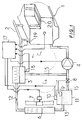
- This primary circuit C1 admits a secondary circuit C2 bypass for the treatment of the vapor phase.
- This second circuit C2 comprises a line 12 connecting the upper part of the phase separator 3 where the steam circulates, to an exchanger 6, where the condensate is collected, in which communicates with a tank 11 via the line 13.
- This tank 11 is provided a valve 10 for adjusting the pressure therein.
- the bypass generated by the second circuit ends in line 15 connecting the reservoir 11 to the pump 4, line 15 is equipped with a valve 8 controlled by the level of liquid in the reservoir 11 by means of a float device 9.
- the implementation of the pump 4, the fan 7 and the valve 10 is controlled by an electronic computer 17 as a function of different parameters: the temperature of the liquid in the phase separator (probe 18), the power of the motor, the temperature at the walls of the combustion chambers, or the vacuum rate at the outlet of the water chamber (conductimetric probe 19).
- the cooling fluid Before starting the engine 1, the cooling fluid is in liquid form and is only present in the primary circuit C1 except for a small amount retained in the tank 11, the valve 8 is in the closed position, preventing the passage of the liquid from the primary circuit C1 to the tank 11 and the exchanger 6.
- the computer 17 When starting the computer 17 generates a setpoint P1 for the pressure prevailing in the tank 11 and therefore in the entire cooling device via the exchanger 6 and line 12. This pressure is generated by the operation of the valve 10.
- the computer 17 also determines a flow rate value Q1 for the pump 4.
- the cooling fluid circulates according to the primary circuit C1 until the liquid begins to boil in the water chamber 20 at contact of the hot walls of the combustion chambers.
- the collector 2 discharges a liquid-vapor mixture.
- the phases are separated in the separator 3.
- the liquid continues to circulate in a closed loop in the primary circuit C1.
- the vapor imprints on the second circuit C2, said branch circuit, and passes through the exchanger 6, expelling the air which is there and compressing it in the tank 11.
- the condensate feeds the reservoir 11 and thus raises the level of the liquid.
- a level threshold is exceeded, the float device 9 forming a level sensor opens the valve 8 which allows to recirculate in the primary circuit or loop C1 a certain amount of liquid. The float device 9 closes the valve 8 as soon as the level has dropped sufficiently.
- the computer 17 controls the operation of the fan in order to accelerate the condensation at the level of the radiator 6 and if the condensation is not sufficient, maneuver the valve 10 so as to escape the compressed air beforehand stored in the tank 11.
- the pressure prevailing in the circuit is monitored by the temperature sensor 18 placed in the lower part of the phase separator 3 in contact with the liquid phase.
- This regulation therefore makes it possible to maintain an almost constant pressure and therefore a fixed vaporization temperature, which does not require frequent opening of the regulation valve.
- the computer 17 When, during operation, the engine power exceeds a predetermined threshold, the computer 17 then generates a second setpoint P2 for the pressure prevailing in the cooling circuit with P2 ⁇ P1, by controlling the fan 7 and the valve 10.
- the flow rate of the pump 4 is modified and brought to a value Q2 with Q2> Q1.
- the system By lowering the boiling point and increasing the coolant flow, the system is able to meet increased cooling needs by using the same device and the same amount of coolant.
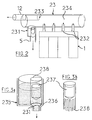
- Figure 2 specifies a preferred embodiment of the phase separator 3 and the collector 2 described above.
- a phase separator requires a large volume so as to slow down the liquid vapor mixture upon entry and thus reduce the effect of the drag force of the two phases.
- the two phases are then separated by their gravitational force: the vapor exits from the top of the separator, while the liquid collected at the bottom of the container exits from the bottom.
- the steam collector As for the steam collector, its role is to facilitate the evacuation of steam from the engine to the condenser. With its vertical pipes located to the right of the cylinder head of the engine it reduces the risk of a boiling crisis by homogenizing the vacuum rate and the temperature of the two-phase flow.
- a collector-separator assembly usually occupies a large volume that is not compatible with the requirements of today's vehicles.
- the separator and the collector have been combined into a single assembly 23.
- This assembly comprises a plurality of vertical pipes 232, a cylindrical chamber 234, a steam outlet 233 and a water outlet 231 fitted with an anti-steam valve.
- the vertical conduits 232 protrude inside the chamber 234 up to about a third of the height of the latter.
- the liquid vapor vapor mixture discharged directly from the engine can freely emerge from the conduits 232 into the chamber 234.
- the vapor exits from the top of the separator towards the condenser via the conduit 12, while the liquid falls to the bottom of the collector where it is then evacuated down through line 5 after passing through the anti-vapor valve.
- This anti-vapor valve is specified in accordance with Figures 3a and 3b.
- the role of this valve is to prohibit any passage of steam in the circuit 5 for returning the liquid to the engine, a passage which could cause harmful depressions.
- the valve is housed in a cavity 235 at the bottom of which the water outlet orifice 231 is formed.
- This orifice is provided with a seat 236 which can be closed off by the lower end of a float 237 forming a needle.
- the float 237 is held above the seat, housed in a cylindrical guide tube 238 closed in its upper part and perforated in its lower part for the passage of the liquid.
- the condenser 6 described above is of the two pass type. It is formed by a radiator 46 comprising two vertical distribution boxes: a first box 460 and a second box 461, these boxes communicate with one another by bundles 462 of tubes of small diameter extending substantially horizontally.
- the first box 460 where the steam supply line 12 opens out is split into two half-boxes by a horizontal partition wall.
- the steam enters the upper half-box and crosses the bundles of horizontal tubes 462 to reach the second box 461. Part of the steam condenses during this passage and flows to the bottom of the second box 461.
- the residual steam is sucked up and reintroduced into the upper half-box using a suction system actuated by a turbine 463. Due to the low pressure drop between the inlet and the outlet of this type of condenser , the turbine requires only a small driving power.
- each of these orifices is provided with a vapor valve 464 similar to that described above.
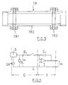
- FIG. 5 shows more precisely a sectional view of the conductimetric probe 19 of the means for measuring the vacuum rate. It essentially consists of two annular electrodes 191 - 192 inserted coaxially at a certain distance from each other in an insulating and heat-resistant cylinder 190. This assembly thus produced forms an outlet from the cooling circuit connecting the outlet of the engine water chamber to the separator.
- FIG. 6 represents the electrical circuit connected to the output of the electrodes and allowing the measurement of the average vacuum rate. It consists of a conductivity meter C associated with an integrator I.
- the conductivity meter comprises: a voltage source U o connected to one of the electrodes of the conductimetric probe, a resistor R1 connected between earth and the second electrode of the probe.
- the integrator conventionally comprises an operational amplifier T1 and a capacitor C1.
- the probe having a conductance G constitutes with the resistor R1 a divider bridge on which the measurement of the vacuum rate can be preveled by measuring the voltage U r across the resistor R1.
- FIG. 7 shows an alternative embodiment of the cooling circuit in which the vent valve 10 is removed. It appears in fact that if such a purging system is simple to implement, it nevertheless has certain drawbacks, among which may be mentioned the loss of coolant and the acceleration of the aging of the latter by oxygenation.
- Such a system makes it possible to adjust the pressure of the circuit in a way that is simple, safe and stable: a simple pressure on the bellows increases the pressure of the circuit unlike a purge system which requires a longer time to adjust the pressures.
- the present circuit comprises a primary circuit for circulation of the cooling fluid V1.
- the primary circuit V1 includes the "water chamber" of the engine 1, a vapor separator-collector 23, a pipe 5 equipped with a non-return valve 55 which makes it possible to connect the lower part of the separator collecting the liquid to a feed pump 4 and which continues from the pump to the inlet of the water chamber.
- the vapor phase is treated in a secondary circuit V2 bypass to the circuit V1 where a pipe 12 connects the steam outlet of the separator 23 to the inlet of the condenser 46, a precision sensor equips this pipe.
- a turbine 122 is inserted before the inlet of the condenser, in order to facilitate the extraction of the engine outlet steam if the latter was problematic.
- the condensate is collected in a line 13 fitted with a non-return valve 131.
- This line communicates with a variable volume tank 51 and extends to a valve 8 controlled by the computer.
- the V2 branch ends with a line connecting the valve 8 to the pump 4.
- This circuit being completely closed, there is no vent valve as in the device described above, it is necessary to place a safety valve 47 in the upper part of the condenser 46. This has for purpose of avoiding any increase in pressure that could not be controlled.
- the origin of this overpressure can be a pump failure or blockage of a valve for example.
- variable volume tank 51 is then in the minimum position.
- the two-phase liquid-vapor mixture is separated in the collector-separator 23.
- the liquid continues to circulate in the loop V1.
- the vapor imprints the line 12 of the circuit V2 and enters the condenser 46.
- the occupation of a certain volume, in the pipe 123 and the exchanger 46, by the steam causes the evacuation of a corresponding volume of liquid towards the variable-volume tank 51.
- the computer 171 receiving information from the pressure 121 authorizes a progressive displacement of the bellows forming the reservoir 51 so as to maintain the pressure substantially constant.
- the computer 17 starts the fan 7 and opens the valve 81.
- the computer 171 then controls the pressure and the cooling of the fluid by more or less condensing the vapor in the exchanger. It simultaneously controls the variable volume tank so as to attenuate the pressure fluctuations which are too great, by varying the volume of the bellows as required.
- the computer 171 varies the setpoint of the actuators (pump, fan, bellows) so as to adapt P and Q to the desired operating regime.
- the safety valve will release a certain amount of vapor.
- the computer 17 then immediately compensates for this loss of fluid, by reducing the volume of the bellows 51 to reinject the liquid into the circuit.
- non-return valves 51 and 131 The purpose of the non-return valves 51 and 131 is to avoid any liquid rising by the lines 5 and 12 when the volume of the bellows is reduced.
- the condensation of the vapor remaining in the circuit is ended and the volume of the bellows is gradually reduced, so as to be in the initial configuration, that is to say V1 and V2 full of water.
- the pump 4 continues to provide a flow rate in order to mix the fluids of the circuits V1 and V2.
Landscapes
- Engineering & Computer Science (AREA)
- Mechanical Engineering (AREA)
- General Engineering & Computer Science (AREA)
- Chemical & Material Sciences (AREA)
- Combustion & Propulsion (AREA)
- Life Sciences & Earth Sciences (AREA)
- Sustainable Development (AREA)
- Physics & Mathematics (AREA)
- Thermal Sciences (AREA)
- Engine Equipment That Uses Special Cycles (AREA)
Claims (15)
- Verfahren zum Kühlen eines Verbrennungsmotors durch Verdampfen eines Kühlfluids im Innern eines die Wasserkammer des Motors enthaltenden primären Strömungskreises (C₁), bei dem die gebildete Dampfphase in den flüssigen Zustand durch Entziehen von Wärme in einem sekundären Kreis (C₂) rückgeführt wird, dadurch gekennzeichnet, daß man durch geeignete Umwälzeinrichtungen (4, 17) ständig einen Durchfluß von Fluid im flüssigen Zustand in dem gesamten primären Strömungskreis (C₁) erzeugt, wobei der in dem primären Kreis (C₁) und dem sekundären Kreis (C₂) herrschende Durchfluß und Druck an einen oder mehrere Betriebsparameter des Motors und/oder physikalische Kenndaten des Kühlfluids angepaßt sind.
- Verfahren zum Kühlen eines Motors nach Anspruch 1, dadurch gekennzeichnet, daß sich der Durchfluß der Kühlflüssigkeit und der Druck, die in dem primären (C₁) und dem sekundären Strömungskreis (C₂) herrschen, mit der von dem Motor abgegebenen Leistung verändern.
- Verfahren zum Kühlen eines Motors nach Anspruch 2, dadurch gekennzeichnet, daß, solange die Leistung des Motors unterhalb eines vorbestimmten Werts liegt, der Durchfluß der Kühlflüssigkeit und der Druck, die in dem ersten (C₁) und dem zweiten Strömungskreis (C₂) herrschen, auf vorbestimmten Werten Q₁ bzw. P₁ konstant gehalten werden, und daß, wenn die Leistung des Motors diesen vorbestimmten Wert überschreitet, dieser Durchfluß und dieser Druck auf neue vorbestimmte Werte Q₂ und P₂ gebracht werden, wobei Q₂ > Q₁ und P₂ < P₁.
- Vorrichtung zum Kühlen eines Verbrennungsmotors mit einem primären Strömungskreis (C₁), der die Wasserkammer (20) des Motors enthält, in der die Verdampfung eines Kühlfluids durchgeführt wird, und einem sekundären Kreis (C₂), bei dem die gebildete Dampfphase durch Entziehen von Wärme in den flüssigen Zustand rückgeführt wird, dadurch gekennzeichnet, daß sie Einrichtungen zur Umwälzung (4, 17) aufweist, die durch einen ständigen Durchfluß von Fluid im flüssigen Zustand in dem gesamten primären Strömungskreis (C₁) ausgelegt sind, wobei der Durchfluß und der Druck, die in dem primären (C₁) und dem sekundären Kreis (C₂) herrschen, an einen oder mehrere Betriebspararneter des Motors und/oder physikalische Kenndaten des Kühlfluids angepaßt sind.
- Vorrichtung zum Kühlen nach Anspruch 4, dadurch gekennzeichnet, daß der primäre Strömungskreis (C₁) der Kühlflüssigkeit aus der Wasserkammer des Motors, einer Sammelleitung (2, 23), einer Phasentrennvorrichtung (3, 23) und einer Rücklaufleitung (5) zur Wasserkammer, die mit einer hydraulischen Pumpe (4) ausgestattet ist, besteht.
- Vorrichtung zum Kühlen nach Anspruch 5, dadurch gekennzeichnet, daß die Sammelleitung und die Phasentrennvorrichtung in einer einzigen Einheit (23) vereinigt sind.
- Verfahren zum Kühlen nach einem der Ansprüche 5 bis 6, dadurch gekennzeichnet, daß die Mündung (231) der Rücklaufleitung (5) mit einem Schwimmerventil (237) ausgestattet ist, welches den Durchtritt des Dampfes unterbindet.
- Verfahren zum Kühlen nach einem der Ansprüche 4 bis 7, dadurch gekennzeichnet, daß der sekundäre Entnahmekreis (C₂) einen Wärmetauscher (6, 46), der durch einen Ventilator (7) gekühlt wird und mit der Phasentrennvorrichtung über eine Zufuhrleitung (12) verbunden ist, einen Flüssigkeitsspeicherbehälter (11, 511) und eine Rücklaufleitung (15) zu dem primären Kreis aufweist.
- Verfahren zum Kühlen nach Anspruch 8, dadurch gekennzeichnet, daß der Wärmetauscher aus einem Kühler mit zwei Durchläufen (46) gebildet ist, welche zwei Wassersammelkammern aufweisen, die vertikal angeordnet sind (460, 461), wobei die Wasserkammern über Bündel horizontaler Röhren (462) verbunden sind und die Entleerungsöffnungen des Kondensats, die im Boden der Wasserkammern angeordnet sind, mit Antidampfventilen (464) ausgestattet sind und eine Turbine (463) eine Zirkulation des restlichen Dampfes bis zu seiner vollständigen Kondensation sichert.
- Vorrichtung zum Kühlen nach einem der Ansprüche 8 bis 9, dadurch gekennzeichnet, daß der Flüssigkeitsspeicherbellälter aus einem Speicherbehälter mit veränderlichen, Volumen (511) gebildet ist.
- Vorrichtung zum Kühlen nach Anspruch 10, dadurch gekennzeichnet, daß der Speicherbehälter aus einem Blasebalgraum (512) gebildet ist, dessen Volumen über die Überwachungseinrichtungen gesteuert wird.
- Vorrichtung zum Kühlen nach Anspruch 11, dadurch gekennzeichnet, daß die Rücklaufleitung (15) mit Blockiereinrichtungen (8, 9) versehen ist, die durch den Flüssigkeitspegel in dem Speicherbehälter gesteuert werden.
- Vorrichtung zur Kühlung nach einem der Ansprüche 6 bis 7, dadurch gekennzeichnet, daß der Speicherbehälter (11) mit einem Ventil (10) versehen ist, welches eine Einstellung des Drucks in dem Speicherbehälter und in der Gruppe aus dem primären Kreis und dem sekundären Kreis (C₁, C₂) ermöglicht.
- Vorrichtung zur Kühlung nach einem der Ansprüche 4 bis 12, dadurch gekennzeichnet, daß die Einrichtungen zum Anpassen des Durchflusses und des Druckes der Kühlflüssigkeit an den Betrieb des Motors einen elektronischen Rechner (17) aufweisen, der in Abhängigkeit von der von dem Motor abgegebenen Leistung und von der Temperatur der Flüssigkeit in der Trennvorrichtung (3) und/oder von dem Vakuumgrad den Ventilator (7), das Ventil (10) oder den Blasebalg (512) und die Pumpe (4) steuert.
- Vorrichtung zum Kühlen nach Anspruch 14, dadurch gekennzeichnet, daß die Einrichtungen zum Messen des Vakuumgrades eine Leitfähigkeitssonde (19) mit zwei Elektroden aufweisen, die am Ausgang der Wasserkammer angeordnet sind.
Applications Claiming Priority (2)
| Application Number | Priority Date | Filing Date | Title |
|---|---|---|---|
| FR9015002 | 1990-11-30 | ||
| FR9015002A FR2669962B1 (fr) | 1990-11-30 | 1990-11-30 | Procede de refroidissement par evaporation pour moteur a combustion interne et dispositif de mise en óoeuvre. |
Publications (2)
| Publication Number | Publication Date |
|---|---|
| EP0489628A1 EP0489628A1 (de) | 1992-06-10 |
| EP0489628B1 true EP0489628B1 (de) | 1995-12-27 |
Family
ID=9402767
Family Applications (1)
| Application Number | Title | Priority Date | Filing Date |
|---|---|---|---|
| EP19910403235 Expired - Lifetime EP0489628B1 (de) | 1990-11-30 | 1991-11-29 | Verdampfungskühlverfahren für eine Brennkraftmaschine und Einrichtung zur Durchführung dieses Verfahrens |
Country Status (4)
| Country | Link |
|---|---|
| EP (1) | EP0489628B1 (de) |
| DE (1) | DE69115865T2 (de) |
| ES (1) | ES2081456T3 (de) |
| FR (1) | FR2669962B1 (de) |
Families Citing this family (11)
| Publication number | Priority date | Publication date | Assignee | Title |
|---|---|---|---|---|
| FR2697580B1 (fr) * | 1992-10-30 | 1994-12-02 | Renault | Système de refroidissement par évaporation pour moteur à combustion interne. |
| FR2697869B1 (fr) * | 1992-11-06 | 1994-12-09 | Renault | Système de refroidissement pour moteur à combustion interne. |
| FR2721655B1 (fr) * | 1994-06-24 | 1996-08-02 | Renault | Dispositif de refroidissement par évaporation pour moteur à combustion interne. |
| FR2728622A1 (fr) * | 1994-12-21 | 1996-06-28 | Renault | Dispositif de refroidissement par evaporation pour moteur a combustion interne |
| FR2752016B1 (fr) * | 1996-07-31 | 1998-09-11 | Renault | Dispositif de refroidissement d'un moteur a combustion interne |
| KR20010033628A (ko) * | 1997-12-30 | 2001-04-25 | 아뜰리에 부쉬 에스.에이. | 냉각 장치 |
| CN102721309B (zh) * | 2012-07-18 | 2016-06-01 | 北京德能恒信科技有限公司 | 一种动力热管装置 |
| JP5973019B1 (ja) * | 2015-03-05 | 2016-08-17 | 本田技研工業株式会社 | 沸騰冷却装置 |
| CN107401446B (zh) * | 2017-09-25 | 2019-11-08 | 合肥升园汽车配件有限公司 | 一种具有内置可调节散热片的车载水室 |
| DE102021200549A1 (de) | 2021-01-21 | 2022-07-21 | Psa Automobiles Sa | Verfahren zum Steuern eines Kühlsystems zur Kühlung mindestens einer zu kühlenden Komponente sowie Vorrichtung zur Durchführung des Verfahrens |
| US12234758B1 (en) * | 2024-02-06 | 2025-02-25 | Caterpillar Inc. | Exhaust assembly temperature regulation for shutdown |
Family Cites Families (11)
| Publication number | Priority date | Publication date | Assignee | Title |
|---|---|---|---|---|
| US1812899A (en) * | 1926-10-09 | 1931-07-07 | Waukesha Motor Co | Steam cooling system |
| US2083611A (en) * | 1931-12-05 | 1937-06-15 | Carrier Corp | Cooling system |
| FR973203A (fr) * | 1941-07-16 | 1951-02-08 | Citroen Sa Andre | Perfectionnements au dispositif de refroidissement de moteur à combustion interne |
| US2825317A (en) * | 1956-01-09 | 1958-03-04 | Adolph A Tacchella | Steam separator |
| US2926641A (en) * | 1958-01-20 | 1960-03-01 | Tacchella Inc | Uniform temperature, dual circuit engine cooling system |
| JPS6069232A (ja) * | 1983-09-27 | 1985-04-19 | Nissan Motor Co Ltd | 内燃機関の沸騰冷却装置 |
| JPS6116222A (ja) * | 1984-07-04 | 1986-01-24 | Nissan Motor Co Ltd | エンジンの沸騰冷却装置 |
| US4700664A (en) * | 1984-07-06 | 1987-10-20 | Nissan Motor Co., Ltd. | Cooling system for automotive engine or the like |
| JPH0830412B2 (ja) * | 1984-08-07 | 1996-03-27 | 日産自動車株式会社 | 内燃機関の沸騰冷却装置 |
| JPS6258010A (ja) * | 1985-09-06 | 1987-03-13 | Nissan Motor Co Ltd | 内燃機関の沸騰冷却装置 |
| US4768484A (en) * | 1987-07-13 | 1988-09-06 | General Motors Corporation | Actively pressurized engine cooling system |
-
1990
- 1990-11-30 FR FR9015002A patent/FR2669962B1/fr not_active Expired - Fee Related
-
1991
- 1991-11-29 DE DE1991615865 patent/DE69115865T2/de not_active Expired - Fee Related
- 1991-11-29 EP EP19910403235 patent/EP0489628B1/de not_active Expired - Lifetime
- 1991-11-29 ES ES91403235T patent/ES2081456T3/es not_active Expired - Lifetime
Also Published As
| Publication number | Publication date |
|---|---|
| FR2669962A1 (fr) | 1992-06-05 |
| EP0489628A1 (de) | 1992-06-10 |
| FR2669962B1 (fr) | 1994-09-16 |
| ES2081456T3 (es) | 1996-03-16 |
| DE69115865T2 (de) | 1996-08-29 |
| DE69115865D1 (de) | 1996-02-08 |
Similar Documents
| Publication | Publication Date | Title |
|---|---|---|
| EP0489628B1 (de) | Verdampfungskühlverfahren für eine Brennkraftmaschine und Einrichtung zur Durchführung dieses Verfahrens | |
| US4706636A (en) | Purge and prime fuel delivery system and method | |
| FR2472738A1 (fr) | Indicateur de niveau d'eau pour reacteur nucleaire | |
| FR2674446A1 (fr) | Dispositif de filtration et de communication entre l'atmosphere et l'interieur d'un carter. | |
| FR2730789A1 (fr) | Dispositif de conditionnement d'un liquide avec regulation de temperature | |
| FR2928867A1 (fr) | Dispositif et procede de chauffage d'un habitacle de vehicule automobile, en particulier un vehicule electrique. | |
| EP0545795A1 (de) | Kühlungsverfahren und Einrichtung für eine Brennkraftmaschine mit stark wechselender Last | |
| FR2482906A1 (fr) | Perfectionnements aux systemes de refroidissement de moteurs de vehicules a radiateur associe a un vase d'expansion | |
| CH660072A5 (fr) | Installation de chauffage d'un liquide. | |
| FR2979387A1 (fr) | Circuit de carburant dans une turbomachine | |
| FR3074531A1 (fr) | Installation pour une turbomachine | |
| EP0284528A1 (de) | Brennstoffzufuhrvorrichtung für eine Brennkraftmaschine, insbesondere eine Dieselmaschine | |
| FR2728622A1 (fr) | Dispositif de refroidissement par evaporation pour moteur a combustion interne | |
| FR2721655A1 (fr) | Dispositif de refroidissement par évaporation pour moteur à combustion interne. | |
| EP0767081B1 (de) | Wärmerückgewinnungsanlage aus Fahrzeugabgasen | |
| FR2691504A1 (fr) | Dispositif de refroidissement d'un moteur thermique comprenant un condenseur. | |
| FR3076903A1 (fr) | Procédé de détermination de l'état thermodynamique du carburant dans un système de carburant | |
| FR3009018B1 (fr) | Circuit de refroidissement d'un moteur thermique de vehicule automobile et procede de gestion associe | |
| FR3096404A1 (fr) | Dispositif de régulation de la température d’au moins un élément d'un moteur thermique suralimenté | |
| FR2736385A1 (fr) | Dispositif fonctionnant en mode diphasique pour le refroidissement d'un moteur a combustion interne | |
| WO2021165096A1 (fr) | Procédé de mesure d'un débit de liquide à la sortie d'une pompe | |
| FR3162480A1 (fr) | Dispositif de chauffage d'un carburant dans un circuit d'alimentation d'une turbomachine d’aeronef, turbomachine d’aeronef et procede de chauffage d'un carburant correspondant | |
| FR3163137A1 (fr) | Système d’alimentation en gaz d’un appareil consommateur de gaz d’un ouvrage flottant | |
| FR2739170A1 (fr) | Reservoir hydropneumatique anti-belier avec dispositif d'admission et de regulation d'air, procede d'admission d'air | |
| EP4423377A1 (de) | Erkennung der anwesenheit von kraftstoff im öl eines flugzeugmotors |
Legal Events
| Date | Code | Title | Description |
|---|---|---|---|
| PUAI | Public reference made under article 153(3) epc to a published international application that has entered the european phase |
Free format text: ORIGINAL CODE: 0009012 |
|
| AK | Designated contracting states |
Kind code of ref document: A1 Designated state(s): DE ES FR GB IT |
|
| 17P | Request for examination filed |
Effective date: 19921116 |
|
| 17Q | First examination report despatched |
Effective date: 19930917 |
|
| GRAA | (expected) grant |
Free format text: ORIGINAL CODE: 0009210 |
|
| AK | Designated contracting states |
Kind code of ref document: B1 Designated state(s): DE ES FR GB IT |
|
| ITF | It: translation for a ep patent filed | ||
| REF | Corresponds to: |
Ref document number: 69115865 Country of ref document: DE Date of ref document: 19960208 |
|
| GBT | Gb: translation of ep patent filed (gb section 77(6)(a)/1977) |
Effective date: 19960124 |
|
| REG | Reference to a national code |
Ref country code: ES Ref legal event code: FG2A Ref document number: 2081456 Country of ref document: ES Kind code of ref document: T3 |
|
| PLBE | No opposition filed within time limit |
Free format text: ORIGINAL CODE: 0009261 |
|
| STAA | Information on the status of an ep patent application or granted ep patent |
Free format text: STATUS: NO OPPOSITION FILED WITHIN TIME LIMIT |
|
| 26N | No opposition filed | ||
| PGFP | Annual fee paid to national office [announced via postgrant information from national office to epo] |
Ref country code: GB Payment date: 19971013 Year of fee payment: 7 |
|
| PGFP | Annual fee paid to national office [announced via postgrant information from national office to epo] |
Ref country code: FR Payment date: 19971113 Year of fee payment: 7 |
|
| PGFP | Annual fee paid to national office [announced via postgrant information from national office to epo] |
Ref country code: DE Payment date: 19971115 Year of fee payment: 7 |
|
| PGFP | Annual fee paid to national office [announced via postgrant information from national office to epo] |
Ref country code: ES Payment date: 19971117 Year of fee payment: 7 |
|
| PG25 | Lapsed in a contracting state [announced via postgrant information from national office to epo] |
Ref country code: GB Free format text: LAPSE BECAUSE OF NON-PAYMENT OF DUE FEES Effective date: 19981129 |
|
| PG25 | Lapsed in a contracting state [announced via postgrant information from national office to epo] |
Ref country code: ES Free format text: LAPSE BECAUSE OF EXPIRATION OF PROTECTION Effective date: 19981130 |
|
| GBPC | Gb: european patent ceased through non-payment of renewal fee |
Effective date: 19981129 |
|
| PG25 | Lapsed in a contracting state [announced via postgrant information from national office to epo] |
Ref country code: FR Free format text: LAPSE BECAUSE OF NON-PAYMENT OF DUE FEES Effective date: 19990730 |
|
| REG | Reference to a national code |
Ref country code: FR Ref legal event code: ST |
|
| PG25 | Lapsed in a contracting state [announced via postgrant information from national office to epo] |
Ref country code: DE Free format text: LAPSE BECAUSE OF NON-PAYMENT OF DUE FEES Effective date: 19990901 |
|
| REG | Reference to a national code |
Ref country code: ES Ref legal event code: FD2A Effective date: 20010301 |
|
| PG25 | Lapsed in a contracting state [announced via postgrant information from national office to epo] |
Ref country code: IT Free format text: LAPSE BECAUSE OF NON-PAYMENT OF DUE FEES;WARNING: LAPSES OF ITALIAN PATENTS WITH EFFECTIVE DATE BEFORE 2007 MAY HAVE OCCURRED AT ANY TIME BEFORE 2007. THE CORRECT EFFECTIVE DATE MAY BE DIFFERENT FROM THE ONE RECORDED. Effective date: 20051129 |