EP0489629B1 - Scheibenwischerarm mit Federstange, insbesondere für Kraftfahrzeuge - Google Patents
Scheibenwischerarm mit Federstange, insbesondere für Kraftfahrzeuge Download PDFInfo
- Publication number
- EP0489629B1 EP0489629B1 EP91403239A EP91403239A EP0489629B1 EP 0489629 B1 EP0489629 B1 EP 0489629B1 EP 91403239 A EP91403239 A EP 91403239A EP 91403239 A EP91403239 A EP 91403239A EP 0489629 B1 EP0489629 B1 EP 0489629B1
- Authority
- EP
- European Patent Office
- Prior art keywords
- wiper arm
- spring
- partition
- windshield wiper
- guide rod
- Prior art date
- Legal status (The legal status is an assumption and is not a legal conclusion. Google has not performed a legal analysis and makes no representation as to the accuracy of the status listed.)
- Expired - Lifetime
Links
- 238000005192 partition Methods 0.000 claims description 23
- 230000000284 resting effect Effects 0.000 claims description 2
- 230000014759 maintenance of location Effects 0.000 claims 2
- 230000006835 compression Effects 0.000 description 4
- 238000007906 compression Methods 0.000 description 4
- 230000000694 effects Effects 0.000 description 2
- 230000000295 complement effect Effects 0.000 description 1
- 230000001419 dependent effect Effects 0.000 description 1
- 239000011521 glass Substances 0.000 description 1
- 230000005484 gravity Effects 0.000 description 1
- 239000002184 metal Substances 0.000 description 1
- 238000005096 rolling process Methods 0.000 description 1
- 238000010408 sweeping Methods 0.000 description 1
Images

Classifications
-
- B—PERFORMING OPERATIONS; TRANSPORTING
- B60—VEHICLES IN GENERAL
- B60S—SERVICING, CLEANING, REPAIRING, SUPPORTING, LIFTING, OR MANOEUVRING OF VEHICLES, NOT OTHERWISE PROVIDED FOR
- B60S1/00—Cleaning of vehicles
- B60S1/02—Cleaning windscreens, windows or optical devices
- B60S1/04—Wipers or the like, e.g. scrapers
- B60S1/32—Wipers or the like, e.g. scrapers characterised by constructional features of wiper blade arms or blades
- B60S1/34—Wiper arms; Mountings therefor
- B60S1/3463—Means to press blade onto screen
- B60S1/3465—Means to press blade onto screen with coil springs
- B60S1/3468—Mountings therefor
-
- B—PERFORMING OPERATIONS; TRANSPORTING
- B60—VEHICLES IN GENERAL
- B60S—SERVICING, CLEANING, REPAIRING, SUPPORTING, LIFTING, OR MANOEUVRING OF VEHICLES, NOT OTHERWISE PROVIDED FOR
- B60S1/00—Cleaning of vehicles
- B60S1/02—Cleaning windscreens, windows or optical devices
- B60S1/04—Wipers or the like, e.g. scrapers
- B60S1/32—Wipers or the like, e.g. scrapers characterised by constructional features of wiper blade arms or blades
- B60S1/34—Wiper arms; Mountings therefor
Definitions
- the present invention relates to a wiper arm with a spring guide rod, in particular for a motor vehicle.
- wiper arms comprising a drive head on which is articulated, by means of a cylindrical articulation axis, a brush holder carrying articulation, in a manner known per se, a brush for windscreen wiper capable of sweeping a glass surface, such as a motor vehicle windshield.
- These arms comprise, in addition, an elastic system interposed between the brush holder and the drive head so as to maintain, during the operation of the wiper constituted by the arm and the brush, an elastic support of said brush. wiper on the surface to be wiped.
- the elastic system generally consists of a coil spring which can work either in tension or in compression.
- Such a spring guide rod such as that described for example in document DE-A-1 505 347, has a first end passing through an opening provided in a partition carried by the brush holder, this partition serving to support the one end of the spring, the other end of the spring resting on a bearing surface provided in the body of the spring guide rod which has a second end which is articulated on the drive head about a deflection axis.
- This pivoting takes place under the action of a torque applied manually by the user and a stop is provided for limiting the disengagement movement of the wiper blade holder relative to the windshield.
- this rod can pivot around the axis of travel and, by gravity, the spring slides along this rod until it drops to the inside the engine compartment, which can generate damage inside it.
- the present invention proposes to remedy the drawbacks mentioned above by presenting a wiper arm in which the spring guide rod will be held on said arm even if the stop is exceeded.
- the wiper arm in particular for a motor vehicle, comprising a drive head, a brush holder articulated by an axis on said head and an elastic system supported in compression by a part on a spring guide rod carried by said drive head and on the other hand on a partition integral with the brush holder, said spring guide rod passing through an opening provided in this partition, is characterized in that holding means are provided between the brush holder bulkhead and the spring guide rod.
- the spring guide rod will be kept at least at the level of the partition that the brush carries in the event of the stop being exceeded.
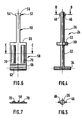
- a wiper arm 2 consists of a drive head 4 carrying a hinge pin 6 around which pivots a brush holder 8 by one of its ends, the other of its ends carrying, in a manner known per se, a connecting and articulation member of a wiper blade.
- the brush holder 8 generally has a sectional shape of inverted U consisting of a core 10 and two side wings 12, 14 enveloping the drive head 4, this head ( Figure 1 ) having a bore 16 orthogonal to the axis 6 so as to be able to be connected to a wiping drive mechanism generating an alternating rotational movement, such as a wiper gear motor (not shown).
- An elastic system here a coil spring 18 working in compression, is interposed between the drive head 4 and the brush holder 8 so as to exert on said brush holder a force tending to direct it towards the surface to be wiped (not shown).
- the spring 18 bears on the one hand on a partition 20 provided orthogonally to the wings 12, 14 and to the core 10 of the brush holder and on the other hand on a bearing surface 22 carried by a spring guide rod 24 .
- the spring guide rod 24 has a first section 26, of cylindrical shape in section, one end of which passes through an opening 28, also cylindrical, provided in the partition 20 , said spring guide rod continuing opposite to its other end by a flange 30 of larger diameter, this cylindrical flange 30 having, opposite the opening 28, the bearing surface 22, this flange continuing towards the drive head 4 by a second section 32, cylindrical in section, which ends with a bar 34 orthogonal to the second section so as to form an inverted T.
- the bar 34 is supported in a housing 36 provided in the drive head 4 so as to allow a certain movement of said rod during the operation of the wiper arm.
- the housing 36 is open in the direction of the spring guide rod 24.
- the wiper arm carries means 38 for holding the spring guide rod 24 on the brush holder 8.
- These means 38 generally consist of an assembly of the bayonet type and for this the opening 28 provided in the partition 20 has two diametrically opposite grooves 40, 42 closed at one of their ends and opening out through the other of their ends in the opening 28 while being arranged in a substantially vertical direction shown in FIG. 2 by the axis XX ′.
- the spring guide rod 24 has, at its free end 44 of the first section 26, two protrusions 46, 48 also arranged diametrically opposite having a dimension and a shape substantially identical to those of the grooves 40, 42, these protrusions being located in a plane identical in direction to that passing through the axis of movement of the bar 34.
- the protuberances 46, 48 are in a plane offset to that of the axis XX ′ of the grooves 40, 42, here offset in an orthogonal plane.
- the spring 18 is trapped between the partition 20 and the bearing surface 22 by urging the spring guide rod towards the drive head until the protuberances 40, 42 come to bear on the partition 20 in now maintaining the rod 24 and the spring 18 on the brush holder and it suffices to introduce the bar 34 into the housing 36 to make the arm 2 operational.
- the spring guide rod 24 cannot leave the opening 28 of the partition 20 by pressing the protrusions 46, 48 on the face of the partition 20 opposite that on which the spring 18 is supported and will also serve as a second stop means in the case where the stop provided between the brush holder and the head disappears during the maneuver.
- the guide rod spring and spring 18 will be maintained on the brush holder 8, even if the torque in rotation about the axis 6 of the brush holder is such that the stop between the head and the brush holder is erased with the sole consequence of bringing the bar 34 out of the housing 36, the spring guide rod and the spring remaining connected to the brush holder and it suffices only to replace the bar 34 in its housing 36 to make the arm operational as a whole.
- the spring guide rod 49 is produced from a cut and folded metal strip and comprises a first part of rectangular shape 50 of elongated shape carrying at one of its ends a second part of rectangular shape 52 of larger transverse dimension so as to create, as previously indicated, two protrusions 54, 56, said part 50 continuing at its other end by a third part 58 also of rectangular shape of larger transverse dimension than that of the transverse dimension of the part 52 so as to present a bearing surface 60 arranged opposite the protuberances 54, 56 formed by the second rectangular part 52.
- the third part 58 has at its free end an axis 62 formed by rolling this free end so as to have a substantially cylindrical surface, this axis serving as the axis of movement of the spring guide rod 49 while being housed in a housing 64 carried identically to that of Figure 1 by the drive head 66 with an open face facing the partition of the brush holder.
- the spring guide rod 49 can easily replace the spring guide rod 24 described in relation with FIG. 1, while having the same abutment means which, in the case of the spring guide rod 49, consist of the protrusions 54, 56 which cooperate, if necessary, with the face of the partition opposite to that on which s supports the spring.
- the protrusions are protrusions reported by any appropriate means.
Landscapes
- Engineering & Computer Science (AREA)
- Mechanical Engineering (AREA)
- Motor Or Generator Current Collectors (AREA)
- Transmission Devices (AREA)
Claims (9)
- Scheibenwischerarm, insbesondere für ein Kraftfahrzeug, enthaltend einen Antriebskopf (4), einen Wischblatthalter (8), der mittels einer Achse (6) gelenkig am genannten Kopf angebracht ist, und ein elastisches System (18), welches unter Einwirkung eines Drucks einerseits auf einer Federstange (24, 49) aufliegt, die vom genannten Antriebskopf getragen wird, und andererseits auf einer fest mit dem Wischblatthalter (8) verbundenen Trennwand (20), wobei die genannte Stange durch eine in dieser Trennwand vorgesehene Öffnung (28) hindurchtritt, dadurch gekennzeichnet, daß zwischen der Trennwand (20) des Wischblatthalters (8) und der Federstange (24, 49) Haltemittel (40, 42, 46, 48, 54, 56) vorgesehen sind.
- Scheibenwischerarm nach Anspruch 1, dadurch gekennzeichnet, daß die Haltemittel aus Anschlägen (46, 48, 54, 56) bestehen, die auf der Trennwand (20) aufliegen.
- Scheibenwischerarm nach Anspruch 2, dadurch gekennzeichnet, daß die Anschläge (46, 48, 54, 56) auf der Federstange (24, 29) aufliegen.
- Scheibenwischerarm nach einem der Ansprüche 2 oder 3, dadurch gekennzeichnet, daß die Anschläge aus Ausstülpungen (46, 48, 54, 52) der Federstange (24, 49) bestehen.
- Scheibenwischerarm nach einem der vorherigen Ansprüche, dadurch gekennzeichnet, daß die Trennwand (20) eine mit zwei Nuten (40, 42) versehene Öffnung (28) aufweist.
- Scheibenwischerarm nach einem der vorherigen Ansprüche, dadurch gekennzeichnet, daß die Nuten (40, 42) in einer Ebene angeordnet sind, die gegenüber der Ebene der Ausstülpungen (46, 48, 52, 54) versetzt ist.
- Scheibenwischerarm nach einem der vorherigen Ansprüche, dadurch gekennzeichnet, daß die Nuten (40, 42) und die Ausstülpungen (46, 48, 54, 56) in einer Bajonett-Anordnung verwendet werden.
- Scheibenwischerarm nach einem der vorherigen Ansprüche, dadurch gekennzeichnet, daß die Federstange (24, 49) eine auf einem offenen Aufnahmesitz (36, 64) ruhende Verschiebeachse (34, 62) aufweist.
- Scheibenwischerarm nach einem der vorherigen Ansprüche, dadurch gekennzeichnet, daß die Federstange (24, 49) Vertiefungen (68, 70) aufweist.
Applications Claiming Priority (2)
| Application Number | Priority Date | Filing Date | Title |
|---|---|---|---|
| FR9015117 | 1990-12-03 | ||
| FR9015117A FR2669881B1 (fr) | 1990-12-03 | 1990-12-03 | Bras d'essuie-glace a tige guide de ressort, notamment pour vehicule automobile. |
Publications (2)
| Publication Number | Publication Date |
|---|---|
| EP0489629A1 EP0489629A1 (de) | 1992-06-10 |
| EP0489629B1 true EP0489629B1 (de) | 1994-03-09 |
Family
ID=9402841
Family Applications (1)
| Application Number | Title | Priority Date | Filing Date |
|---|---|---|---|
| EP91403239A Expired - Lifetime EP0489629B1 (de) | 1990-12-03 | 1991-11-29 | Scheibenwischerarm mit Federstange, insbesondere für Kraftfahrzeuge |
Country Status (3)
| Country | Link |
|---|---|
| EP (1) | EP0489629B1 (de) |
| DE (1) | DE69101369T2 (de) |
| FR (1) | FR2669881B1 (de) |
Families Citing this family (1)
| Publication number | Priority date | Publication date | Assignee | Title |
|---|---|---|---|---|
| FR2703644B1 (fr) * | 1993-04-08 | 1995-05-12 | Valeo Systemes Dessuyage | Essuie-glace équipé d'une cale de montage. |
Family Cites Families (3)
| Publication number | Priority date | Publication date | Assignee | Title |
|---|---|---|---|---|
| US2071310A (en) * | 1935-04-26 | 1937-02-16 | Trico Products Corp | Windshield cleaner |
| DE848754C (de) * | 1949-03-22 | 1952-09-08 | Bosch Gmbh Robert | Scheibenwischer, insbesondere fuer Kraftfahrzeuge |
| IT967567B (it) * | 1972-09-16 | 1974-03-11 | Magneti Marelli Spa | Braccio per spazzole di tergicri stallo di veicoli in genere |
-
1990
- 1990-12-03 FR FR9015117A patent/FR2669881B1/fr not_active Expired - Fee Related
-
1991
- 1991-11-29 EP EP91403239A patent/EP0489629B1/de not_active Expired - Lifetime
- 1991-11-29 DE DE1991601369 patent/DE69101369T2/de not_active Expired - Fee Related
Also Published As
| Publication number | Publication date |
|---|---|
| FR2669881A1 (fr) | 1992-06-05 |
| EP0489629A1 (de) | 1992-06-10 |
| DE69101369T2 (de) | 1994-06-16 |
| DE69101369D1 (de) | 1994-04-14 |
| FR2669881B1 (fr) | 1993-01-22 |
Similar Documents
| Publication | Publication Date | Title |
|---|---|---|
| FR2629030A1 (fr) | Porte-balais d'essuie-glace comportant un verrou | |
| EP1545947A1 (de) | Anordnung zur befestigung eines scheibenwischerblatts an einem wischerarm | |
| FR2693693A1 (fr) | Bras d'essuie-glace. | |
| FR2673151A1 (fr) | Bras d'essuie-glace, notamment pour vehicule automobile. | |
| EP2883761B1 (de) | Befestigungsklammer eines Flüssigkeitskreislaufschlauchs an einem Antriebsarm eines Scheibenwischerblattes eines Fahrzeugs | |
| EP0479659B1 (de) | Scheibenwischerarm besonders für Kraftfahrzeuge | |
| EP0489813B1 (de) | Scheibenwischersystem mit ferngesteuerter berührungskraftregelung | |
| FR2544677A1 (fr) | Dispositif de balayage pour glaces de vehicules automobiles | |
| EP0489629B1 (de) | Scheibenwischerarm mit Federstange, insbesondere für Kraftfahrzeuge | |
| FR2499920A1 (fr) | Bras d'essuie-glace | |
| BE1001062A5 (fr) | Bras moteur pour balais d'essuie-glace avec ressort helicoidal a torsion. | |
| FR2899857A1 (fr) | Dispositif de debrayabilite d'un bras d'essuie-glace pour automobiles | |
| EP0575241B1 (de) | Gelenkverbindung zwischen dem gehäuseartigen Gelenkteil und dem Befestigungsteil eines Scheibenwischers | |
| FR2620671A1 (fr) | Dispositif d'essuyage de vitres de vehicules automobiles | |
| WO1981000235A1 (fr) | Bras d'essuie-glace soumis a l'action d'un ressort en compression | |
| EP0664246B1 (de) | Scheibenwischer für Kraftfahrzeug | |
| FR2689839A1 (fr) | Bras d'essuie-glace de véhicule automobile. | |
| EP0565436B1 (de) | Wischerarm | |
| EP0678428A1 (de) | Scheibenwischer mit zwei Blättern an einem einzigen Arm | |
| FR2720708A1 (fr) | Essuie-glace comportant des moyens pour régler la valeur nominale du couple d'essuyage. | |
| FR2772704A1 (fr) | Frein a tambour permettant un montage de cable en aveugle | |
| FR2492750A1 (fr) | Dispositif de liaison articulee pour balai d'essuie-glace | |
| FR2490564A1 (fr) | Bras d'essuie-glace pour vehicules automobiles | |
| WO2007071671A1 (fr) | Agencement d'un bras d'essuie-glace de vehicule automobile sur une tete d'entrainement | |
| CH689693A5 (fr) | Dispositif d'essuie-glace à deux balais mono-bras. |
Legal Events
| Date | Code | Title | Description |
|---|---|---|---|
| PUAI | Public reference made under article 153(3) epc to a published international application that has entered the european phase |
Free format text: ORIGINAL CODE: 0009012 |
|
| AK | Designated contracting states |
Kind code of ref document: A1 Designated state(s): DE ES GB IT |
|
| 17P | Request for examination filed |
Effective date: 19920925 |
|
| 17Q | First examination report despatched |
Effective date: 19930806 |
|
| GRAA | (expected) grant |
Free format text: ORIGINAL CODE: 0009210 |
|
| AK | Designated contracting states |
Kind code of ref document: B1 Designated state(s): DE ES GB IT |
|
| PG25 | Lapsed in a contracting state [announced via postgrant information from national office to epo] |
Ref country code: IT Free format text: LAPSE BECAUSE OF FAILURE TO SUBMIT A TRANSLATION OF THE DESCRIPTION OR TO PAY THE FEE WITHIN THE PRE;WARNING: LAPSES OF ITALIAN PATENTS WITH EFFECTIVE DATE BEFORE 2007 MAY HAVE OCCURRED AT ANY TIME BEFORE 2007. THE CORRECT EFFECTIVE DATE MAY BE DIFFERENT FROM THE ONE RECORDED.SCRIBED TIME-LIMIT Effective date: 19940309 Ref country code: ES Free format text: THE PATENT HAS BEEN ANNULLED BY A DECISION OF A NATIONAL AUTHORITY Effective date: 19940309 |
|
| REF | Corresponds to: |
Ref document number: 69101369 Country of ref document: DE Date of ref document: 19940414 |
|
| GBT | Gb: translation of ep patent filed (gb section 77(6)(a)/1977) |
Effective date: 19940408 |
|
| PLBE | No opposition filed within time limit |
Free format text: ORIGINAL CODE: 0009261 |
|
| STAA | Information on the status of an ep patent application or granted ep patent |
Free format text: STATUS: NO OPPOSITION FILED WITHIN TIME LIMIT |
|
| 26N | No opposition filed | ||
| PGFP | Annual fee paid to national office [announced via postgrant information from national office to epo] |
Ref country code: GB Payment date: 19961028 Year of fee payment: 6 |
|
| PGFP | Annual fee paid to national office [announced via postgrant information from national office to epo] |
Ref country code: DE Payment date: 19970124 Year of fee payment: 6 |
|
| PG25 | Lapsed in a contracting state [announced via postgrant information from national office to epo] |
Ref country code: GB Free format text: LAPSE BECAUSE OF NON-PAYMENT OF DUE FEES Effective date: 19971129 |
|
| GBPC | Gb: european patent ceased through non-payment of renewal fee |
Effective date: 19971129 |
|
| PG25 | Lapsed in a contracting state [announced via postgrant information from national office to epo] |
Ref country code: DE Free format text: LAPSE BECAUSE OF NON-PAYMENT OF DUE FEES Effective date: 19980801 |