EP0489631B1 - Scheibenwaschanlage für Scheibenwischermechanismen - Google Patents
Scheibenwaschanlage für Scheibenwischermechanismen Download PDFInfo
- Publication number
- EP0489631B1 EP0489631B1 EP91403241A EP91403241A EP0489631B1 EP 0489631 B1 EP0489631 B1 EP 0489631B1 EP 91403241 A EP91403241 A EP 91403241A EP 91403241 A EP91403241 A EP 91403241A EP 0489631 B1 EP0489631 B1 EP 0489631B1
- Authority
- EP
- European Patent Office
- Prior art keywords
- sheet metal
- pipe
- orifice
- spraying device
- tubular
- Prior art date
- Legal status (The legal status is an assumption and is not a legal conclusion. Google has not performed a legal analysis and makes no representation as to the accuracy of the status listed.)
- Expired - Lifetime
Links
- 230000007246 mechanism Effects 0.000 title claims description 12
- 239000002184 metal Substances 0.000 claims description 14
- 239000007788 liquid Substances 0.000 claims description 8
- 239000000463 material Substances 0.000 claims description 6
- 238000005507 spraying Methods 0.000 claims 6
- 239000007921 spray Substances 0.000 claims 2
- 238000000465 moulding Methods 0.000 description 4
- 230000008901 benefit Effects 0.000 description 3
- 208000031968 Cadaver Diseases 0.000 description 2
- 230000003100 immobilizing effect Effects 0.000 description 2
- 238000000034 method Methods 0.000 description 2
- 230000015556 catabolic process Effects 0.000 description 1
- 230000000295 complement effect Effects 0.000 description 1
- 239000002826 coolant Substances 0.000 description 1
- 230000008878 coupling Effects 0.000 description 1
- 238000010168 coupling process Methods 0.000 description 1
- 238000005859 coupling reaction Methods 0.000 description 1
- 238000012423 maintenance Methods 0.000 description 1
- 239000007769 metal material Substances 0.000 description 1
- 230000035515 penetration Effects 0.000 description 1
- 230000008439 repair process Effects 0.000 description 1
- 230000000717 retained effect Effects 0.000 description 1
- 238000005406 washing Methods 0.000 description 1
Images

Classifications
-
- B—PERFORMING OPERATIONS; TRANSPORTING
- B60—VEHICLES IN GENERAL
- B60S—SERVICING, CLEANING, REPAIRING, SUPPORTING, LIFTING, OR MANOEUVRING OF VEHICLES, NOT OTHERWISE PROVIDED FOR
- B60S1/00—Cleaning of vehicles
- B60S1/02—Cleaning windscreens, windows or optical devices
- B60S1/04—Wipers or the like, e.g. scrapers
- B60S1/32—Wipers or the like, e.g. scrapers characterised by constructional features of wiper blade arms or blades
- B60S1/34—Wiper arms; Mountings therefor
- B60S1/3415—Wiper arms; Mountings therefor with means for supplying cleaning fluid to windscreen cleaners, e.g. washers
-
- B—PERFORMING OPERATIONS; TRANSPORTING
- B60—VEHICLES IN GENERAL
- B60S—SERVICING, CLEANING, REPAIRING, SUPPORTING, LIFTING, OR MANOEUVRING OF VEHICLES, NOT OTHERWISE PROVIDED FOR
- B60S1/00—Cleaning of vehicles
- B60S1/02—Cleaning windscreens, windows or optical devices
- B60S1/46—Cleaning windscreens, windows or optical devices using liquid; Windscreen washers
- B60S1/48—Liquid supply therefor
- B60S1/52—Arrangement of nozzles; Liquid spreading means
- B60S1/522—Arrangement of nozzles; Liquid spreading means moving liquid spreading means, e.g. arranged in wiper arms
Definitions
- the present invention relates to a windshield washer device for wiper mechanisms, in particular for motor vehicles.
- the windshield washer devices for wiper mechanisms have all been of great mechanical complexity and have a poor guarantee of tightness, generally corresponding to two different types: on the one hand, those which project the liquid onto the windshield at the same rate as the movement of the squeegee arm, and, on the other hand, those who project it from stable points in a predetermined direction which crosses the path of the squeegees.
- the most common of the first of these devices consists in mounting a tube or a nozzle fixed on the squeegee arm, or independent of it but moving with it, supplied by an appropriate conduit, flexible or not, the nozzle projecting the liquid directly onto the windshield, according to the movement of the arm. Mention may be made, in this first type, of the patents GB-A-410,259, US-A-2,866,996, US-A-3,234,579; and German DE-C-1,113,877 and DE-U-1,737,296.
- a sprinkler device in particular for wiper mechanisms, in which a nozzle is arranged on the wiper arm driven in rotation by a motor shaft passing through a planned opening in the sheet metal of the vehicle body, said device comprising an annular piece, in the form of a socket, surrounding the shaft and arranged opposite the internal face of the sheet metal of the body, a tubular conduit arranged parallel to the axis of the piece and which has two ends of connection for the supply and outlet conduits of the liquid to be projected by the nozzle, a cup-shaped ring arranged on the external face of the sheet surrounding the motor shaft.
- the invention makes it possible to find a solution to the drawbacks of the devices mentioned above, by presenting an extremely simple device, both as regards first equipment and in the event of subsequent replacement.
- the device coolant in particular for wiper mechanisms, in which a nozzle is arranged on the wiper arm driven in rotation by a motor shaft passing through an opening provided in the sheet metal of the vehicle body, said device comprising an annular piece, in the form of a socket, surrounding the shaft and arranged opposite the internal face of the body sheet, a tubular conduit disposed parallel to the axis of the part and which has two connection ends for the conduits supply and outlet of the liquid to be projected by the nozzle, a cup-shaped ring disposed on the external face of the sheet by surrounding the motor shaft (Device of the type disclosed by GB-A-2 206 483) is characterized in that the annular part is applied against the sheet by interposing an elastic lamellar seal which surrounds the opening provided on the sheet of the bodywork, in that the tubular conduit passes through the lamellar joint by an orifice and the sheet by an orifice, the orifices being coaxial and in that the orifice of the lamellar joint is provided
- the maintenance of the annular part or socket, avoided against the body is achieved by the tubular body of the motor element, against which it is supported, and thanks to another external complementary annular part, assembled around a tubular extension of this body by which it crosses the actuating shaft of the mechanism; it is firmly fixed with a threaded nut on a threaded projecting sector outside this tubular extension.
- connection between the nozzle proper and the end of the supply duct assembled to the annular fixing part is carried out, advantageously and according to a method already known, by means of a flexible duct arranged amply and helically around the body through which the motor shaft passes so that it can easily follow the movements of the mechanism.
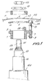
- the part 1 fits against the sheet 2, by inserting a lamellar seal 4 which has a central opening 5 which coincides with the internal diameter of the part 1 and with an opening 6 provided in the sheet of the bodywork.
- the part 1 has a conduit 7, molded in its own body, intended for supplying the washing liquid, parallel to the axis of said part and which has openings at the ends 8, 9 for coupling the internal conduits 10 and external 11 of the liquid supply to the orientable nozzle 12.
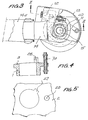
- This nozzle is mounted on the body of the articulated cap 13 which covers the assembly end of the fork 14 of the squeegee arm 14a on the shaft 15 of the mechanism motor of said arm.
- the nozzle itself follows the movements of the squeegee arm, so that the jet it produces is always projected into the area to be washed by the squeegee.
- the motor shaft 15 exceeds by crossing a tubular body 16 which has a shoulder 16a on which the part 1 rests, the tubular body 16 passing through the part 1, the joint 4 and the sheet metal 2 of the bodywork.
- the assembly is fixed to the body by means of a cup-shaped ring 17, assembled on the tubular body 16 and retained against the body by the nut 18, which is assembled in the threaded extension of the end 19 of the body. tubular 16, from which the shaft 15 protrudes.
- the fork 14 is held on said shaft in a conventional manner by virtue of the nut 20 which is assembled on the thread 21 of the outer end of the shaft 15 and through the knurled conical section 22 thereof.
- the sheet 2 of the body also has an orifice 23 which corresponds to the duct 7 in order to allow the latter to pass outside.
- Another similar orifice 24 is also provided in the lamellar seal 4; it is provided, on the edge of the opening against the sheet 2, with a projecting collar 25, the external diameter of which corresponds to that of the orifice 23 and the internal diameter corresponds to or is slightly less than that of the walls outside of duct 7.
- the part 1 has, projecting from its side which can be attached to the sheet 2, a projection 26 which can be coupled to the notch 27 of the opening 6 of the sheet 2 of the bodywork by crossing a groove in the joint 4 for centering and immobilizing said part (Figure 5).
- connection between the duct 7 and the nozzle 12 is carried out according to a method already known, thanks to the aforementioned flexible duct 11, which has a large and helical position around the body 16.
- the conduit 7a is formed of an independent part, of a material different, united to the body of the part 1 during the molding of the latter.
- the part 1 can be made of a suitable plastic material, while the duct 7a will be formed from a suitably machined metallic material. In both cases, the practical results with regard to the functions of said conduit are exactly the same.
- this mounting system can be applied to any type of mechanism of the indicated type.
- it is very suitable for mounting on new equipment given its ease of initial placement, to which must be added the ease of its assembly or possible dismantling in the event of a breakdown or replacement of the mechanism.
Landscapes
- Engineering & Computer Science (AREA)
- Mechanical Engineering (AREA)
- Water Supply & Treatment (AREA)
- Nozzles (AREA)
- Pivots And Pivotal Connections (AREA)
Claims (6)
- Scheibenwaschanlage, insbesondere für Scheibenwischermechanismen, bei der eine Spritzdüse (12) auf dem Scheibenwischerarm (13, 14, 14a) angeordnet ist, der von einer durch eine Öffnung (6) im Blech (2) der Fahrzeugkarosserie hindurchgehenden Antriebswelle (15) drehend angetrieben wird, wobei die besagte Anlage ein ringförmiges Teil (1) in Form einer Hülse umfaßt, das die Welle (15) umschließt und gegenüber der Innenseite des Karosserieblechs (2) angeordnet ist, sowie eine parallel zur Achse des Teils (1) angeordnete Rohrleitung (7), die zwei Enden (8, 9) für den Anschluß der Zuleitungskanäle (10) und den Austritt (11) der durch die Düse (12) aufzuspritzenden Flüssigkeit aufweist, und einen schalenförmigen Ring (17), der an der Außenseite des Blechs (2) angeordnet ist und die Antriebswelle (15) umschließt , dadurch gekennzeichnet, daß das ringförmige Teil (1) am Blech (2) unter Einfügung einer elastischen Lamellendichtung (4) angebracht wird, welche die am Karosserieblech (2) vorgesehene Öffnung (6) umschließt, daß die Rohrleitung (7) durch die Lamellendichtung (4) durch eine entsprechende Öffnung (24) und durch das Blech (2) durch eine entsprechende Öffnung (23) hindurchgeht, wobei die Öffnungen (23, 24) koaxial verlaufen, und daß die Öffnung (24) der Lamellendichtung (4) mit einem vorspringenden Kragen (25) versehen ist, der in die entsprechende Öffnung (23) im Blech eingesetzt wird und dessen Innendurchmesser höchstens gleich dem Durchmesser des durch ihn hindurchgenenden Zuleitungskanals (7) ist.
- Scheibenwaschanlage nach Anspruch 1 , dadurch gekennzeichnet, daß der Zuleitungskanal (7) einstückig mit dem rohrförmigen Teil (1) ausgeführt ist.
- Scheibenwaschanlage nach Anspruch 2 , dadurch gekennzeichnet, daß der Zuleitungskanal (7) und das Teil (1) aus dem gleichen Werkstoff hergestellt werden.
- Scheibenwaschanlage nach Anspruch 1, dadurch gekennzeichnet, daß der Zuleitungskanal (7) unabhängig von dem rohrförmigen Teil (1) ausgeführt ist.
- Scheibenwaschanlage nach Anspruch 4 , dadurch gekennzeichnet, daß das rohrförmige Teil (1) am Zuleitungskanal (7) aufgeformt ist.
- Scheibenwaschanlage nach einem der vorangehenden Ansprüche, dadurch gekennzeichnet, daß das rohrförmige Teil (1) einen Vorsprung (26) aufweist, der mit einer Ausklinkung (27) zusammenwirkt, die am Blech (2) vorgesehen ist, um seine Vorpositionierung zu ermöglichen.
Applications Claiming Priority (2)
| Application Number | Priority Date | Filing Date | Title |
|---|---|---|---|
| ES9003075 | 1990-12-03 | ||
| ES9003075A ES2027130A6 (es) | 1990-12-03 | 1990-12-03 | Sistema de montaje del rociador en mecanismos limpiaparabrisas. |
Publications (2)
| Publication Number | Publication Date |
|---|---|
| EP0489631A1 EP0489631A1 (de) | 1992-06-10 |
| EP0489631B1 true EP0489631B1 (de) | 1997-03-12 |
Family
ID=8269874
Family Applications (1)
| Application Number | Title | Priority Date | Filing Date |
|---|---|---|---|
| EP91403241A Expired - Lifetime EP0489631B1 (de) | 1990-12-03 | 1991-11-29 | Scheibenwaschanlage für Scheibenwischermechanismen |
Country Status (3)
| Country | Link |
|---|---|
| EP (1) | EP0489631B1 (de) |
| DE (1) | DE69125108T2 (de) |
| ES (1) | ES2027130A6 (de) |
Cited By (1)
| Publication number | Priority date | Publication date | Assignee | Title |
|---|---|---|---|---|
| DE19811183B4 (de) * | 1998-03-14 | 2007-01-25 | Volkswagen Ag | Wisch-Wasch-Anlage für Scheiben von Fahrzeugen |
Family Cites Families (5)
| Publication number | Priority date | Publication date | Assignee | Title |
|---|---|---|---|---|
| DE1244596B (de) * | 1962-07-21 | 1967-07-13 | Bosch Gmbh Robert | Wisch- und Spuelgeraet fuer Fensterscheiben, insbesondere fuer Windschutzscheiben von Kraftfahrzeugen |
| CA938756A (en) * | 1970-09-14 | 1973-12-25 | Bachrach Charles | Vehicle headlight cleaning system |
| JPS5858987U (ja) * | 1981-10-16 | 1983-04-21 | 本田技研工業株式会社 | 自動二輸車等のワイパ−スイツチ装置 |
| DE3511811C2 (de) * | 1985-03-30 | 1995-06-14 | Teves Gmbh Alfred | Reinigungsvorrichtung, insbesondere für Scheiben von Kraftfahrzeugen |
| JPH0544217Y2 (de) * | 1987-07-08 | 1993-11-09 |
-
1990
- 1990-12-03 ES ES9003075A patent/ES2027130A6/es not_active Expired - Lifetime
-
1991
- 1991-11-29 EP EP91403241A patent/EP0489631B1/de not_active Expired - Lifetime
- 1991-11-29 DE DE69125108T patent/DE69125108T2/de not_active Expired - Fee Related
Cited By (1)
| Publication number | Priority date | Publication date | Assignee | Title |
|---|---|---|---|---|
| DE19811183B4 (de) * | 1998-03-14 | 2007-01-25 | Volkswagen Ag | Wisch-Wasch-Anlage für Scheiben von Fahrzeugen |
Also Published As
| Publication number | Publication date |
|---|---|
| DE69125108T2 (de) | 1997-11-06 |
| EP0489631A1 (de) | 1992-06-10 |
| ES2027130A6 (es) | 1992-05-16 |
| DE69125108D1 (de) | 1997-04-17 |
Similar Documents
| Publication | Publication Date | Title |
|---|---|---|
| EP0344822A2 (de) | Abnehmbares Kugelgelenk | |
| EP0669237B1 (de) | Scheibenwischer mit verbesserten Verbindungsmitteln zwischen der Antriebswelle und dem Befestigungsteil | |
| FR3096325A1 (fr) | Dispositif de balai d’essuie-glace | |
| FR3013288A1 (fr) | Balai d'essuie-glace d'une vitre d'un vehicule | |
| FR2673153A1 (fr) | Dispositif de lave-glace, pour mecanismes d'essuie-glace. | |
| EP0489631B1 (de) | Scheibenwaschanlage für Scheibenwischermechanismen | |
| EP0491603B1 (de) | Verbindungsglied zwischen einem Scheibenwischerarm, insbesondere für Kraftfahrzeug | |
| FR2735735A1 (fr) | Dispositif d'essuyage d'une vitre de vehicule automobile muni de moyens perfectionnes d'alimentation d'un dispositif d'arrosage fixe sur l'essuie-glace | |
| FR2863991A1 (fr) | Agencement pour le guidage d'un arbre d'entrainement de mecanisme d'essuyage permettant l'effacement de l'arbre d'entrainement en cas de choc | |
| FR2776606A1 (fr) | Unite d'essuie-glace | |
| EP0788950A1 (de) | Kraftfahrzeug-Scheibenwischervorrichtung mit Scheibenwischer-Indexierungsmittelnunter Berücksichtigung der Antriebswelle | |
| EP0985577B1 (de) | Steuerungseinrichtung eines verstellbaren Teils eines Kfz-Scheinwerfers | |
| EP0577499A1 (de) | Lenkstockschalter, insbesondere für Kraftfahrzeuge | |
| FR3047953A1 (fr) | Systeme d’essuyage d’une surface vitree dote d’un dispositif de lavage a raccordement facilite. | |
| FR2700740A1 (fr) | Ensemble de jet pour lave-vitre de véhicule. | |
| FR2684343A1 (fr) | Dispositif de projection d'un liquide de nettoyage integre a un balai d'essui-glace, en particulier pour vehicule automobile. | |
| FR3035631A1 (fr) | Dispositif d’essuyage d’une surface vitree dote d’un systeme de projection de liquide de lavage a raccordement facilite | |
| EP0873922B1 (de) | Motorgetriebe für Scheibenwischer eines Kraftfahrzeuges mit einer Waschwasser-Rohrleitung | |
| EP2069186B1 (de) | Spurstangen-faltenbalg für das lenksystem eines kraftfahrzeugs | |
| FR2639593A3 (fr) | Dispositif d'essuie-glace, en particulier pour le pare-brise arriere d'un vehicule automobile | |
| FR2654186A1 (fr) | Phare a faisceau orientable. | |
| EP0467750A1 (de) | Antriebsarmmontagevorrichtung, insbesondere für Scheibenwischer | |
| EP0059657A1 (de) | Servolenkungsventil mit vereinfachter Montage | |
| EP1800949B1 (de) | Signalleuchteneinheit für ein Kraftfahrzeug mit einer Stange, welche mit einem Positionierungsteil und einem Teil zur Befestigung an der Karosserie versehen ist. | |
| FR2681033A1 (fr) | Dispositif de lavage d'une vitre, telle qu'une lunette arriere, d'un vehicule automobile. |
Legal Events
| Date | Code | Title | Description |
|---|---|---|---|
| PUAI | Public reference made under article 153(3) epc to a published international application that has entered the european phase |
Free format text: ORIGINAL CODE: 0009012 |
|
| AK | Designated contracting states |
Kind code of ref document: A1 Designated state(s): DE GB |
|
| 17P | Request for examination filed |
Effective date: 19920918 |
|
| 17Q | First examination report despatched |
Effective date: 19931014 |
|
| GRAG | Despatch of communication of intention to grant |
Free format text: ORIGINAL CODE: EPIDOS AGRA |
|
| GRAH | Despatch of communication of intention to grant a patent |
Free format text: ORIGINAL CODE: EPIDOS IGRA |
|
| GRAH | Despatch of communication of intention to grant a patent |
Free format text: ORIGINAL CODE: EPIDOS IGRA |
|
| GRAA | (expected) grant |
Free format text: ORIGINAL CODE: 0009210 |
|
| AK | Designated contracting states |
Kind code of ref document: B1 Designated state(s): DE GB |
|
| PG25 | Lapsed in a contracting state [announced via postgrant information from national office to epo] |
Ref country code: GB Effective date: 19970312 |
|
| REF | Corresponds to: |
Ref document number: 69125108 Country of ref document: DE Date of ref document: 19970417 |
|
| GBV | Gb: ep patent (uk) treated as always having been void in accordance with gb section 77(7)/1977 [no translation filed] |
Effective date: 19970312 |
|
| PLBE | No opposition filed within time limit |
Free format text: ORIGINAL CODE: 0009261 |
|
| STAA | Information on the status of an ep patent application or granted ep patent |
Free format text: STATUS: NO OPPOSITION FILED WITHIN TIME LIMIT |
|
| 26N | No opposition filed | ||
| PGFP | Annual fee paid to national office [announced via postgrant information from national office to epo] |
Ref country code: DE Payment date: 19981119 Year of fee payment: 8 |
|
| PG25 | Lapsed in a contracting state [announced via postgrant information from national office to epo] |
Ref country code: DE Free format text: LAPSE BECAUSE OF NON-PAYMENT OF DUE FEES Effective date: 20000901 |