EP0489874B1 - Chariot elevateur pour passages etroits - Google Patents
Chariot elevateur pour passages etroits Download PDFInfo
- Publication number
- EP0489874B1 EP0489874B1 EP90917937A EP90917937A EP0489874B1 EP 0489874 B1 EP0489874 B1 EP 0489874B1 EP 90917937 A EP90917937 A EP 90917937A EP 90917937 A EP90917937 A EP 90917937A EP 0489874 B1 EP0489874 B1 EP 0489874B1
- Authority
- EP
- European Patent Office
- Prior art keywords
- truck
- wheel
- turning
- steering angle
- wheels
- Prior art date
- Legal status (The legal status is an assumption and is not a legal conclusion. Google has not performed a legal analysis and makes no representation as to the accuracy of the status listed.)
- Expired - Lifetime
Links
- 230000002441 reversible effect Effects 0.000 claims abstract description 6
- 238000013459 approach Methods 0.000 claims description 2
- 230000003028 elevating effect Effects 0.000 claims description 2
- 230000001154 acute effect Effects 0.000 claims 1
- 238000003780 insertion Methods 0.000 description 6
- 230000037431 insertion Effects 0.000 description 6
- 230000001965 increasing effect Effects 0.000 description 4
- 230000000694 effects Effects 0.000 description 2
- 238000000605 extraction Methods 0.000 description 1
- 230000002706 hydrostatic effect Effects 0.000 description 1
- 230000004048 modification Effects 0.000 description 1
- 238000012986 modification Methods 0.000 description 1
Images

Classifications
-
- B—PERFORMING OPERATIONS; TRANSPORTING
- B66—HOISTING; LIFTING; HAULING
- B66F—HOISTING, LIFTING, HAULING OR PUSHING, NOT OTHERWISE PROVIDED FOR, e.g. DEVICES WHICH APPLY A LIFTING OR PUSHING FORCE DIRECTLY TO THE SURFACE OF A LOAD
- B66F9/00—Devices for lifting or lowering bulky or heavy goods for loading or unloading purposes
- B66F9/06—Devices for lifting or lowering bulky or heavy goods for loading or unloading purposes movable, with their loads, on wheels or the like, e.g. fork-lift trucks
- B66F9/075—Constructional features or details
- B66F9/08—Masts; Guides; Chains
- B66F9/10—Masts; Guides; Chains movable in a horizontal direction relative to truck
- B66F9/105—Articulated, i.e. front chassis with wheels and mast rotatable relative to rear chassis with wheels
-
- B—PERFORMING OPERATIONS; TRANSPORTING
- B66—HOISTING; LIFTING; HAULING
- B66F—HOISTING, LIFTING, HAULING OR PUSHING, NOT OTHERWISE PROVIDED FOR, e.g. DEVICES WHICH APPLY A LIFTING OR PUSHING FORCE DIRECTLY TO THE SURFACE OF A LOAD
- B66F9/00—Devices for lifting or lowering bulky or heavy goods for loading or unloading purposes
- B66F9/06—Devices for lifting or lowering bulky or heavy goods for loading or unloading purposes movable, with their loads, on wheels or the like, e.g. fork-lift trucks
- B66F9/075—Constructional features or details
- B66F9/08—Masts; Guides; Chains
- B66F9/10—Masts; Guides; Chains movable in a horizontal direction relative to truck
Definitions
- EP 0 303 413 shows a narrow aisle lift truck having a body and a mast structure which are pivoted together about a main vertical or king pin axis.
- the body has wheels on a first common axis and the mast structure has feet with wheels on a second common axis. When the axes are parallel the parts are pivotally related for straight ahead, or straight back, travel.
- the mast has a carriage for elevation of forks which are for insertion and retraction of a load to and from the stack in which the aisle extends. Steering is effected by driving the mast structure about the king pin by any suitable means.
- a truck having all of these mentioned features is herein called "of the kind referred to”.
- DE 1049307B shows a truck having front wheels only driven by separate reversible motors which can be controlled individually as to speed. This speed control is used to steer the truck and provide a solution to the problem of the inner and outer wheels moving different distances but because those motors act as the only steering means, there are other problems introduced.
- the reversibility is to allow the truck to go forwards or backwards.
- a forklift truck comprises a pair of driven wheels on a common axis on a rear part a second pair of wheels on a second axis on a front part, a mast with forks for elevating a load and provided on the front part, a pivot connecting the two parts, steering means for turning one of the parts relative to the other, separate reversible driving motors provided one for each of the driven wheels, and means for stopping or changing the direction of rotation of the motor driving the wheel nearest to the centre about which the truck turns as the steering angle approaches and reaches a maximum steering angle.
- the two motors are under the control of circuitry (software) with an input from the steering wheel position, or from micro-switches contacted by parts of the steering gear, according to the angle of turning.
- circuitry software
- the arrangement is most desirably such that in the straight line position both wheels are driven synchronously, and drive to the inside wheel - whichever one is involved according to the direction of turning - is progressively reduced as the radius of turning is reduced down to zero, or first down to zero then reversing of the inside wheel when the steering is near or is on full lock, according to the geometry and design of the truck.
- the second axis wheels may be located at the end of projecting feet, and in any event the design preferably allows the load to descend to ground level. Any projection may assist with stability to prevent the truck overturning especially when in extreme positions.
- the possible geometry of the truck according to the invention may be considered thus: if the centre of turning, which is the intersection of straight lines containing the respective axes of the two pairs of wheels coincides with the ground contact point of the inside driven wheel, then drive of the outside wheel alone is possible with the inside wheel effectively pivoting on the ground. But if said centre is inside the track of the driven wheels then the inner wheel must turn backwards in relation to the outer wheel if extreme tyre wear and loss of control is to be prevented.
- the arrangements according to the invention give advantages in manoeuvreing and maintains control of the vehicle at such times.
- the truck has an extensor mechanism for projecting the forks and load into and out of the stack at the side of the aisle.
- Such a mechanism requires to be particularly rigid in order to support adequate load in the fully extended position, and the effect of the extended load has to be taken into account in calculations relating to the potential stability of the truck. This places severe limits on the designer.
- the extensor mechanism can be avoided thus providing greater simplicity and rigidity in terms of mast, carriage and forks and increasing the limits of load carrying and transferring ability without incurring instability.
- Such a simpler design, according to the invention, has relatively short projecting feet so as to allow for maximum movement of the load forks with the truck (instead of relative to the truck) in the direction transverse to the aisle e.g. for load insertion without coming into contact with the stack face of the aisle, and the same considerations apply in load extraction.
- Such short feet themselves tend to reduce truck stability, although the absence of the extensor mechanism increases stability to a greater extent.
- the increased manoeuvreability and stability, together with the avoidance of the need for the load extensor retractor mechanism is a much greater advantage than the corresponding disadvantage of the need to provide control mechanism for varying wheel speed in relation to steering wheel position.
- FIG. 1 shows a truck provided with a pair of wheels (14 15) located on a common axis, and carried by a body portion (10) which is pivoted to a second part of the truck (16) having short forwardly projecting limbs (18) carrying a pair of non-driven wheels (20) located on a second axis.
- the part (16) is provided with a mast carrying forks (12) to support the load (34).
- This truck is primarily intended to be turned to the left only, and for this purpose wheel (14) is driven and wheel (15) is freely rotatable but not driven.
- the truck is shown in an aisle defined between a pair of parallel aisle faces (30 32) and it is manoeuvreing a load (34) for insertion into the space 36.
- the truck would have to be driven round and positioned in the aisle facing in the opposite direction.
- the centre of turning of the truck is the point (40) which is the intersection of the axes of the front and rear wheels. It lies just outside the wheel base of the wheels (14 15).
- This truck had certain advantages in its manoeuvreability but it was tiring to drive because the steering was very heavy, and inconvenient in that it always had to insert and remove loads on the lefthand side of the vehicle when travelling in a forward direction.
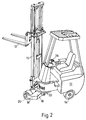
- the truck shown comprises a first part (10) which carries the propulsion means for example storage batteries and electric motors together with the driver's seat and controls.
- the weight is concentrated rearwardly as low down and widespread as possible in the interests of stability of the truck especially when carrying a load on the forks (12).
- the load may be elevated by the forks on the mast (15) and the latter may be telescopically height extendable in conventional fashion.
- the mast may be tilted back in conventional fashion when carrying the load, and of course stability needs to be considered when the truck is on full steering lock.
- the first part of the truck has a pair of coaxial driven wheels (14), the overall width of which (track) plus the usual clearance dictates the aisle width of the warehouse or store in which the truck is to be used.
- the second part of the truck (16) has short limbs (18) carrying the second pair of coaxial wheels (20). These may be of the same track as the wheels (14).
- the two parts (10 16) are pivoted together on a main vertical king pin or like in the part shown by the reference (22). Means are provided for turning the part (18) relative to the part (10) when the steering wheel (24) is turned in conventional manner.
- FIG 3 shows the truck of Figure 2, that is one according to the present invention, but drawn to the same scale and in the same aisle location as Figure 1 .
- the truck can be used to insert and remove loads to left or right, and the disadvantages with the truck of Figure 1 are avoided.
- the proportions of the truck can be changed whilst working within the same set of parameters as to load, size and weight and aisle width.
- the truck can be made wider thus increasing stability.
- the centre of turning (42) lies in the central point of contact of the inner wheel with the ground.
- This wheel (44) is then held stationary insofar as rotation about its axis is concerned whilst the outer wheel (46) drives forwardly for load insertion, or rearwardly during load removal.
- the centre of turning will lie under the wheel (46) and that will be the wheel which is disengaged from drive and or driven rearwardly during load insertion.
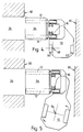
- Figure 4 goes one step further. Again keeping all other things equal the track is still wider, the stability/load possibility is increased, and the centre of turning now lies within the track, that is between the wheels (50,52). In this position inner wheel (50) needs to be driven in the reverse direction relative to the outer wheel for the operation.
- Figure 5 shows a modification of the Figure 4 arrangement when the two parts are arranged to be capable of being turned through more than 90deg.
- the centre of turning (54) can now be brought to the midpoint of the driven wheel track, so that again by driving the wheels in opposite directions but now possibly at the same speed instead of driving the inner wheel in the opposite direction at reduced speed, the load can be moved laterally of the aisle in the final part of the load insertion, or the initial part of the load removal operation.
Landscapes
- Engineering & Computer Science (AREA)
- Transportation (AREA)
- Structural Engineering (AREA)
- Civil Engineering (AREA)
- Life Sciences & Earth Sciences (AREA)
- Geology (AREA)
- Mechanical Engineering (AREA)
- Forklifts And Lifting Vehicles (AREA)
Abstract
Claims (4)
- Chariot élévateur à fourches comportant à sa partie arrière (10) deux roues motrices (14) montées sur un essieu commun, deux autres roues (20) montées à sa partie avant (16) sur un second essieu, un mât (15) équipé de fourches (12) pour lever une charge et, vers l'avant, une articulation qui relie les deux parties, des moyens de conduite (24) pour faire tourner l'une des parties (10,16) par rapport à l'autre, un moteur d'entraînement séparé réversible associé à chaque roue motrice, et un moyen pour arrêter le moteur d'entraînement de la roue située la plus près du centre de rotation du chariot, ou pour changer son sens de rotation, lorsque l'angle de conduite approche et atteint une valeur maximum.
- Chariot selon la revendication 1 dans lequel, en position d'angle de conduite maximum, le centre de rotation (42) du chariot (le point d'intersection des axes des couples de roues respectifs) se trouve dans la zone de contact avec le sol de la roue la plus intérieure (44), et dans lequel la disposition de commande est telle qu'elle arrête, lorsque le dit angle maximum de conduite est atteint, le moteur d'entraînement de la dite roue intérieure.
- Chariot selon la revendication 1 dans lequel, en position d'angle de conduite maximum, le centre de rotation (48) du chariot se trouve situé dans la largeur du chemin de déplacement des roues motrices, et dans lequel la disposition est telle que le moteur d'entraînement de la dite roue intérieure (50) se trouve inversé lorsqu'on atteint le dit angle de conduite maximum.
- Chariot selon la revendication 3 dans lequel, en position d'angle de direction maximum du chariot, les deux parties du chariot font entre elles un angle aigu et le centre de rotation (54) se trouve à mi-chemin entre les roues motrices.
Applications Claiming Priority (3)
| Application Number | Priority Date | Filing Date | Title |
|---|---|---|---|
| GB898917414A GB8917414D0 (en) | 1989-07-29 | 1989-07-29 | Narrow aisle lift truck |
| GB8917414 | 1989-07-29 | ||
| PCT/GB1990/001050 WO1991001938A1 (fr) | 1989-07-29 | 1990-07-06 | Chariot elevateur pour passages etroits |
Publications (2)
| Publication Number | Publication Date |
|---|---|
| EP0489874A1 EP0489874A1 (fr) | 1992-06-17 |
| EP0489874B1 true EP0489874B1 (fr) | 1994-08-31 |
Family
ID=10660875
Family Applications (1)
| Application Number | Title | Priority Date | Filing Date |
|---|---|---|---|
| EP90917937A Expired - Lifetime EP0489874B1 (fr) | 1989-07-29 | 1990-07-06 | Chariot elevateur pour passages etroits |
Country Status (6)
| Country | Link |
|---|---|
| US (1) | US5312219A (fr) |
| EP (1) | EP0489874B1 (fr) |
| CA (1) | CA2064022C (fr) |
| DE (1) | DE69012135T2 (fr) |
| GB (2) | GB8917414D0 (fr) |
| WO (1) | WO1991001938A1 (fr) |
Families Citing this family (23)
| Publication number | Priority date | Publication date | Assignee | Title |
|---|---|---|---|---|
| DE9107488U1 (de) * | 1991-06-18 | 1991-08-29 | Hartig, Jürgen, 3402 Niemetal | Radfahrzeug, insbesondere Forstmaschine |
| GB9200346D0 (en) * | 1992-01-09 | 1992-02-26 | Translift Material Handling | Improvements relating to forklift trucks |
| GB9205800D0 (en) * | 1992-03-17 | 1992-04-29 | British Tech Group | Treatment of fibrotic disorders |
| GB9206824D0 (en) * | 1992-03-28 | 1992-05-13 | Translift Material Handling | Fork lift truck |
| KR0182242B1 (ko) * | 1995-04-19 | 1999-04-15 | 사토 후미오 | 복수의 기기 사이에서 취급매체를 수수하는(주고받는)장치, 이를 구비한 현금처리시스템 및 거래매체의 수수방법 |
| IT1281790B1 (it) * | 1995-05-03 | 1998-03-03 | Carer Snc Dell Ing Angelo Gaet | Carrello elevatore a quattro ruote con stretto raggio di sterzata e stabilita' migliorata |
| GB9700763D0 (en) * | 1997-01-13 | 1997-03-05 | Translift Engineering Limited | Lift truck |
| FR2768714B1 (fr) * | 1997-09-19 | 1999-12-03 | Manitou Bf | Chariot a mat, apte a etre embarque a l'arriere d'un vehicule porteur |
| US20030209371A1 (en) * | 2000-10-27 | 2003-11-13 | Brown Frederick Lesley | Lift truck |
| GB2356611B (en) * | 2000-10-27 | 2003-08-20 | Translift Engineering Ltd | Lift truck |
| IES20010241A2 (en) * | 2001-03-13 | 2002-09-18 | Combilift Res & Dev Ltd | Steering circuit for forklift trucks |
| WO2003029129A1 (fr) * | 2001-10-03 | 2003-04-10 | Aisle-Master Limited | Chariot elevateur a fourches articule |
| US20050061570A1 (en) * | 2002-01-02 | 2005-03-24 | Mcvicar Martin | Four-directional forklift truck |
| GB0200750D0 (en) * | 2002-01-15 | 2002-02-27 | Narrow Aisle Ltd | Lift truck |
| GB0207352D0 (en) * | 2002-03-27 | 2002-05-08 | Narrow Aisle Ltd | Lift truck |
| GB0312343D0 (en) † | 2003-05-30 | 2003-07-02 | Translift Engineering Ltd | Fork lift truck |
| CN101767514A (zh) * | 2010-03-22 | 2010-07-07 | 无锡汇丰机器有限公司 | 一种叉车车轿 |
| CN101774333A (zh) * | 2010-03-23 | 2010-07-14 | 无锡汇丰机器有限公司 | 一种高性能叉车车轿 |
| US8863882B2 (en) | 2010-12-07 | 2014-10-21 | Landoll Corporation | Hydraulic steering system for forklift trucks |
| US8276704B2 (en) | 2010-12-07 | 2012-10-02 | Landoll Corporation | Hydraulic steering system for forklift trucks |
| GB201204387D0 (en) * | 2012-03-12 | 2012-04-25 | Translift Bendi Ltd | Order pickers |
| US9963331B1 (en) * | 2015-09-10 | 2018-05-08 | X Development Llc | Systems and methods for operating a powered pallet jack with steerable forks |
| US10737922B2 (en) * | 2018-08-08 | 2020-08-11 | International Business Machines Corporation | Mechanically actuated load stabilizer for pallet jacks |
Family Cites Families (14)
| Publication number | Priority date | Publication date | Assignee | Title |
|---|---|---|---|---|
| DE1049307B (de) * | 1956-07-21 | 1959-01-22 | Hans Still Ag | Gabelstapler mit schwenkbarem, den Hubmast tragendem Vorderteil des Fahrgestelles |
| US2986295A (en) * | 1957-11-25 | 1961-05-30 | Towmotor Corp | Narrow aisle warehousing lift truck |
| US2957533A (en) * | 1957-12-18 | 1960-10-25 | Shepard Co Lewis | Materials handling trucks |
| US3031024A (en) * | 1959-07-23 | 1962-04-24 | Yale & Towne Mfg Co | All directional industrial truck |
| DE1209450B (de) * | 1960-08-08 | 1966-01-20 | Linde Ag | Lenkeinrichtung fuer einen Hubstapler |
| FR1486006A (fr) * | 1966-07-06 | 1967-06-23 | Kloeckner Werke Ag | élévateur à fourche |
| DE1680249A1 (de) * | 1967-08-05 | 1971-10-21 | Windhoff Rheiner Maschf | Arbeitsfahrzeug |
| US3901339A (en) * | 1974-04-15 | 1975-08-26 | Clark Equipment Co | Hydrostatic drive-steer system |
| US4301881A (en) * | 1979-05-08 | 1981-11-24 | Griffin Hugh A | Vehicle drive system |
| FI77192C (sv) * | 1980-03-10 | 1989-02-10 | Konetehdas Norcar | Hydraulmotordrivet tvådelat terränggående fordon |
| US4621562A (en) * | 1983-05-31 | 1986-11-11 | Monitor Engineers Limited | Remote control robot vehicle |
| DE3441625A1 (de) * | 1984-11-14 | 1986-05-22 | Wacker-Werke Gmbh & Co Kg, 8077 Reichertshofen | Vibrationswalze, insbesondere grabenwalze |
| GB8719175D0 (en) * | 1987-08-13 | 1987-09-23 | Translift Material Handling Lt | Narrow aisle lift truck |
| US4914592A (en) * | 1987-12-03 | 1990-04-03 | Trw Inc. | Apparatus for controlling a steering-by-driving system |
-
1989
- 1989-07-29 GB GB898917414A patent/GB8917414D0/en active Pending
-
1990
- 1990-07-06 DE DE69012135T patent/DE69012135T2/de not_active Expired - Fee Related
- 1990-07-06 US US07/820,886 patent/US5312219A/en not_active Expired - Lifetime
- 1990-07-06 CA CA002064022A patent/CA2064022C/fr not_active Expired - Lifetime
- 1990-07-06 GB GB9015023A patent/GB2234214B/en not_active Expired - Lifetime
- 1990-07-06 WO PCT/GB1990/001050 patent/WO1991001938A1/fr not_active Ceased
- 1990-07-06 EP EP90917937A patent/EP0489874B1/fr not_active Expired - Lifetime
Also Published As
| Publication number | Publication date |
|---|---|
| GB8917414D0 (en) | 1989-09-13 |
| CA2064022C (fr) | 1999-04-06 |
| WO1991001938A1 (fr) | 1991-02-21 |
| GB2234214A (en) | 1991-01-30 |
| GB9015023D0 (en) | 1990-08-29 |
| US5312219A (en) | 1994-05-17 |
| DE69012135T2 (de) | 1995-03-23 |
| DE69012135D1 (de) | 1994-10-06 |
| GB2234214B (en) | 1993-05-26 |
| CA2064022A1 (fr) | 1991-01-30 |
| EP0489874A1 (fr) | 1992-06-17 |
Similar Documents
| Publication | Publication Date | Title |
|---|---|---|
| EP0489874B1 (fr) | Chariot elevateur pour passages etroits | |
| US7900732B2 (en) | Fork lift truck with a single front wheel | |
| CN100506588C (zh) | 具有横行系统的作业车辆 | |
| US20040007414A1 (en) | Forklift with transverse travel system | |
| US3067839A (en) | Material handling vehicle | |
| CN118665627A (zh) | 辅助轮和双轮车 | |
| EP1201596B1 (fr) | Chariot élévateur à fourche | |
| CN107082389B (zh) | 叉车和控制叉车的方法 | |
| US6854552B2 (en) | Fork lift with traverse motion system | |
| CN213679655U (zh) | 一种四向行驶的步行式侧面堆垛车 | |
| US7117962B2 (en) | Articulated forklift truck | |
| CN112209297A (zh) | 一种四向行驶的步行式侧面堆垛车 | |
| US20030132038A1 (en) | Lift truck | |
| GB2265344A (en) | Narrow-aisle fork-lift truck. | |
| CN119118004B (zh) | 一种可横向移动式堆高车 | |
| GB2234487A (en) | Lift trucks | |
| WO1993014017A1 (fr) | Perfectionnements apportes a des chariots elevateurs a fourche | |
| US20030209371A1 (en) | Lift truck | |
| JP2000351595A (ja) | サイドフォーク式搬送用車両 | |
| JPH0544388Y2 (fr) | ||
| US20030070856A1 (en) | Articulated forklift truck | |
| JP2579856B2 (ja) | リーチ型フォークリフト | |
| GB2399062A (en) | Articulated lift truck | |
| AU2001294138A1 (en) | Articulated forklift truck | |
| JPH02279B2 (fr) |
Legal Events
| Date | Code | Title | Description |
|---|---|---|---|
| PUAI | Public reference made under article 153(3) epc to a published international application that has entered the european phase |
Free format text: ORIGINAL CODE: 0009012 |
|
| 17P | Request for examination filed |
Effective date: 19920109 |
|
| AK | Designated contracting states |
Kind code of ref document: A1 Designated state(s): DE FR GB IT |
|
| 17Q | First examination report despatched |
Effective date: 19930303 |
|
| GRAA | (expected) grant |
Free format text: ORIGINAL CODE: 0009210 |
|
| AK | Designated contracting states |
Kind code of ref document: B1 Designated state(s): DE FR GB IT |
|
| REF | Corresponds to: |
Ref document number: 69012135 Country of ref document: DE Date of ref document: 19941006 |
|
| ITF | It: translation for a ep patent filed | ||
| ET | Fr: translation filed | ||
| PLBE | No opposition filed within time limit |
Free format text: ORIGINAL CODE: 0009261 |
|
| STAA | Information on the status of an ep patent application or granted ep patent |
Free format text: STATUS: NO OPPOSITION FILED WITHIN TIME LIMIT |
|
| 26N | No opposition filed | ||
| PG25 | Lapsed in a contracting state [announced via postgrant information from national office to epo] |
Ref country code: DE Effective date: 19960402 |
|
| PG25 | Lapsed in a contracting state [announced via postgrant information from national office to epo] |
Ref country code: FR Effective date: 19960430 |
|
| REG | Reference to a national code |
Ref country code: FR Ref legal event code: ST |
|
| REG | Reference to a national code |
Ref country code: FR Ref legal event code: ST |
|
| REG | Reference to a national code |
Ref country code: FR Ref legal event code: ST |
|
| REG | Reference to a national code |
Ref country code: GB Ref legal event code: 732E |
|
| REG | Reference to a national code |
Ref country code: GB Ref legal event code: IF02 |
|
| PG25 | Lapsed in a contracting state [announced via postgrant information from national office to epo] |
Ref country code: IT Free format text: LAPSE BECAUSE OF NON-PAYMENT OF DUE FEES;WARNING: LAPSES OF ITALIAN PATENTS WITH EFFECTIVE DATE BEFORE 2007 MAY HAVE OCCURRED AT ANY TIME BEFORE 2007. THE CORRECT EFFECTIVE DATE MAY BE DIFFERENT FROM THE ONE RECORDED. Effective date: 20050706 |
|
| PGFP | Annual fee paid to national office [announced via postgrant information from national office to epo] |
Ref country code: GB Payment date: 20090702 Year of fee payment: 20 |
|
| REG | Reference to a national code |
Ref country code: GB Ref legal event code: PE20 Expiry date: 20100705 |
|
| PG25 | Lapsed in a contracting state [announced via postgrant information from national office to epo] |
Ref country code: GB Free format text: LAPSE BECAUSE OF EXPIRATION OF PROTECTION Effective date: 20100705 |