EP0489986A1 - Interrupteur de puissance à basse tension avec un moyen de liaison isolant et un écran isolant - Google Patents
Interrupteur de puissance à basse tension avec un moyen de liaison isolant et un écran isolant Download PDFInfo
- Publication number
- EP0489986A1 EP0489986A1 EP90250313A EP90250313A EP0489986A1 EP 0489986 A1 EP0489986 A1 EP 0489986A1 EP 90250313 A EP90250313 A EP 90250313A EP 90250313 A EP90250313 A EP 90250313A EP 0489986 A1 EP0489986 A1 EP 0489986A1
- Authority
- EP
- European Patent Office
- Prior art keywords
- insulating
- insulating plate
- circuit breaker
- low
- voltage circuit
- Prior art date
- Legal status (The legal status is an assumption and is not a legal conclusion. Google has not performed a legal analysis and makes no representation as to the accuracy of the status listed.)
- Granted
Links
- 230000008878 coupling Effects 0.000 claims abstract description 50
- 238000010168 coupling process Methods 0.000 claims abstract description 50
- 238000005859 coupling reaction Methods 0.000 claims abstract description 50
- 238000000034 method Methods 0.000 claims description 8
- 230000008569 process Effects 0.000 claims description 8
- 239000000853 adhesive Substances 0.000 claims description 7
- 238000010791 quenching Methods 0.000 claims description 7
- 230000000171 quenching effect Effects 0.000 claims description 7
- 230000001070 adhesive effect Effects 0.000 claims description 6
- 230000005405 multipole Effects 0.000 claims description 4
- 210000002105 tongue Anatomy 0.000 claims description 4
- 239000004744 fabric Substances 0.000 claims description 2
- 239000012784 inorganic fiber Substances 0.000 claims description 2
- 239000011810 insulating material Substances 0.000 abstract description 5
- 238000009413 insulation Methods 0.000 description 7
- 239000007789 gas Substances 0.000 description 6
- 238000007789 sealing Methods 0.000 description 6
- 238000004519 manufacturing process Methods 0.000 description 4
- 230000000694 effects Effects 0.000 description 3
- 239000000463 material Substances 0.000 description 3
- 239000002184 metal Substances 0.000 description 2
- 238000013459 approach Methods 0.000 description 1
- 238000005452 bending Methods 0.000 description 1
- 238000004870 electrical engineering Methods 0.000 description 1
- 238000010292 electrical insulation Methods 0.000 description 1
- 238000004146 energy storage Methods 0.000 description 1
- 230000002349 favourable effect Effects 0.000 description 1
- 230000006872 improvement Effects 0.000 description 1
- 238000009434 installation Methods 0.000 description 1
- 230000003993 interaction Effects 0.000 description 1
- 238000009421 internal insulation Methods 0.000 description 1
- 230000000717 retained effect Effects 0.000 description 1
- 238000000926 separation method Methods 0.000 description 1
- 239000007787 solid Substances 0.000 description 1
- 238000000638 solvent extraction Methods 0.000 description 1
- 238000003860 storage Methods 0.000 description 1
- 230000007704 transition Effects 0.000 description 1
Images


Classifications
-
- H—ELECTRICITY
- H01—ELECTRIC ELEMENTS
- H01H—ELECTRIC SWITCHES; RELAYS; SELECTORS; EMERGENCY PROTECTIVE DEVICES
- H01H9/00—Details of switching devices, not covered by groups H01H1/00 - H01H7/00
- H01H9/30—Means for extinguishing or preventing arc between current-carrying parts
- H01H9/34—Stationary parts for restricting or subdividing the arc, e.g. barrier plate
-
- H—ELECTRICITY
- H01—ELECTRIC ELEMENTS
- H01H—ELECTRIC SWITCHES; RELAYS; SELECTORS; EMERGENCY PROTECTIVE DEVICES
- H01H9/00—Details of switching devices, not covered by groups H01H1/00 - H01H7/00
- H01H9/30—Means for extinguishing or preventing arc between current-carrying parts
- H01H2009/305—Means for extinguishing or preventing arc between current-carrying parts including means for screening for arc gases as protection of mechanism against hot arc gases or for keeping arc gases in the arc chamber
-
- H—ELECTRICITY
- H01—ELECTRIC ELEMENTS
- H01H—ELECTRIC SWITCHES; RELAYS; SELECTORS; EMERGENCY PROTECTIVE DEVICES
- H01H9/00—Details of switching devices, not covered by groups H01H1/00 - H01H7/00
- H01H9/30—Means for extinguishing or preventing arc between current-carrying parts
- H01H9/38—Auxiliary contacts on to which the arc is transferred from the main contacts
Definitions
- the invention relates to a low-voltage circuit breaker with a contact arrangement comprising a fixed contact unit and a movable contact unit interacting with it, and with a drive device having a selector shaft, wherein a crank arm fastened to the selector shaft and the movable contact unit are articulated to one another by at least one insulating coupling element, and an insulating shield sitting on the coupling member in the open state of the circuit breaker covers an opening of a first insulating plate.
- a circuit breaker of this type is known from DE-C-29 05 854.
- the insulating shield is designed as a fixed component of the coupling element, while the first insulating wall is part of a shell-like insulating component that separates the drive device from the contact arrangement.
- the interaction between the insulating shield and the insulating plate results in a seal between the switching chamber of the circuit breaker and the space accommodating the drive device, in order to prevent leakage of ionized gases during the switching process from the switching chamber and in this way to prevent electrical flashovers.
- a similarly acting arrangement according to DE-A-35 40 655 contains, instead of a solid insulating screen formed in one piece with the coupling member, a relatively thin, plate-shaped insulating screen which has a lower mass than a one-piece molded insulating screen and, because of its lower mass, reduces the energy requirement when switching .
- the insulating screen lies against its edges engaging or delimiting strips or stop surfaces and brings about the desired sealing in this position.
- the shielding effect of the known arrangements consisting of insulating shield and insulating plate is no longer sufficient when a circuit breaker is to be used at a nominal voltage which is above the z.
- the object of the invention is to make circuit breakers of the type mentioned usable for a significantly higher voltage level, for example 1000 V, with basically the same structure and without increasing their dimensions.
- the invention solves this problem on the basis of a circuit breaker of the type mentioned in that a second insulating plate is arranged at a distance from the first insulating plate which corresponds at most to the path of the coupling element during a switching operation, which second insulating plate likewise has an opening for the coupling element to pass through and which is located is located on the side of the insulating screen that is opposite the first insulating plate.
- the length of the coupling element remains unchanged compared to the known circuit breaker.
- the specified dimensioning - at a distance corresponding at most to the path of the coupling element - is to be understood such that a technically required dimensional tolerance is taken into account in the distance between the insulating plates.
- Both the sealing effect described above as well the dimensioning of the length of the coupling element can, according to a further development of the invention, be influenced in a favorable manner in that the first insulating plate is arranged to be movable and can be carried along by the insulating shield from a position relatively close to the second insulating plate during the switching off process. In this way, a labyrinthine arrangement is created with a reduced overall length requirement.
- a further improvement and simplification of the circuit breaker can be contributed by the fact that the first insulating plate is designed to be flexible and, starting from a base plate located below the contact arrangement, extends essentially over the entire height of the contact arrangement and an arc quenching chamber located above the contact arrangement.
- the flexibility eliminates the need to adapt the insulating plate more or less exactly to the contour of the dividing line between the switching chamber and the space accommodating the drive device.
- the extension to the arc quenching chamber also creates uninterrupted insulation inside the circuit breaker with a correspondingly high level of security against flashovers.
- the second insulating plate can also be designed to be flexible. In this way, it is possible to arrange the two insulating plates at a relatively small distance from one another on both sides of the insulating shield seated on the coupling member, and thereby for an arrangement with a particularly high flow resistance to care. During the switching operations, both insulating plates and the insulating shield take part in the movement in whole or in part.
- the second insulating plate can have a lower height than the first insulating plate.
- the first and the second insulating plate can have a width corresponding to the entire width of the contact arrangements have a multi-pole circuit breaker and can be provided with openings for all existing coupling elements.
- the second insulating plate can be provided on one edge with projections which articulate engage in openings in the first insulating plate. This ensures cohesion and relative mobility of the insulating plates in the switching operations in a simple manner.
- the first insulating plate can at least locally carry a layer of an adhesive adhesive near its upper edge.
- Insulation plates made of synthetic resin-bonded organic or inorganic fibers or fabric webs have proven particularly useful, the thickness of the insulation plates being of the order of 1 mm. Depending on the size of the circuit breaker and the insulating plates, thicknesses between about 0.3 and 2 mm can be considered.
- FIG. 1 shows a section of a switching pole of a low-voltage circuit breaker with the associated drive device and an arrangement for sealing between the switching chamber and the drive device.
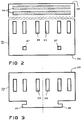
- FIG. 2 shows a first insulating plate
- FIG. 3 represents a second insulating plate
- FIGS. 4, 5 and 6 schematically show the relative positions between the insulating shield seated on a coupling member and a first and a second insulating plate.
- 4 shows an arrangement with stationary insulating plates.
- a stationary and a movable insulating plate are provided in FIG. 5, while the example according to FIG. 6 has two movable insulating plates.
- circuit breaker 1 shows in section a pole of a multi-pole low-voltage circuit breaker of a type such as is described in more detail, for example, in DE-A-35 04 423 or EP-B-0 191 719. Therefore, only the details of the circuit breaker 1 shown for understanding the invention are explained below.
- a housing 2 there are three contact arrangements, designated as a whole by 3, each in a parallel arrangement comprise a fixed contact unit 4 and a movable contact unit 5.
- the term “contact unit” means a multi-part assembly which, in the case of the contact unit 4, comprises a fixed, busbar-like support, at least one main contact attached to it, an arcing horn and, if required, at least one burn-off contact.
- the movable contact unit 5 has a movable contact lever with contact parts arranged in a manner analogous to that of the contact unit 4, and a support 7 which receives the contact unit 5 and can be pivoted about a pivot bearing 6.
- the contact units 4 and 5 are connected to outer connecting rails 12 and 13, respectively, which extend on the back of the housing 2 of the circuit breaker 1 approximately parallel to the rear wall thereof upwards and downwards.
- An example of a suitable contact arrangement can be found in EP-B-0 191 719.
- a spring storage unit 14 which may correspond approximately to the design as described in DE-A-35 42 746.
- the spring-loaded unit 14 interacts with a drive device 15, which comprises articulated toggle levers 16, 17 and 18, which are shown in FIG. 1 in a bent position corresponding to the illustrated switch-off position of the contact arrangement 3.
- a latching device which comprises a release shaft 20, a latch lever 21 and a support lever 22, is shown in the latched state.
- the support lever 22 engages a hinge pin 23 which connects the toggle levers 17 and 18 to one another in an articulated manner.
- the contact arrangement 3 can be moved into the switch-on position by releasing the tensioned energy storage unit 14, which is shown in FIG. 1 of EP-B-0 191 719.
- the toggle lever arrangement described above actuates a switching shaft 24 which is common to all poles of the circuit breaker 1 arranged parallel to one another.
- Crank arms 25 seated on the control shaft 24 are connected in an articulated manner to at least one insulating coupling member 26 which is provided for each pole of the circuit breaker 1 and which in turn is connected in an articulated manner to the carrier 7 of the associated movable contact unit 5.
- two or more parallel coupling elements 26 can be provided, depending on the dimensions of the carrier 7 and how large the power requirement is when switching on.
- the coupling elements 26 thus form the electrical insulation between the movable contact unit 5 and its support 7 and between the drive device 15 which is at ground potential.
- the normal operating voltages occurring in low-voltage circuit breakers only require relatively short insulating distances. However, if the insulating sections are stressed with ionized gases or metal vapor or both media, there is a risk of a flashover between the live and earthed components. Obviously, a simple way to avoid the above-mentioned rollovers would be to dimension the length of the coupling links 26 accordingly. In this way, however, the size of the circuit breaker 1 is undesirably changed because it is then necessary to increase the distance between the contact arrangement 3 and the drive device 15. The following describes how an arrangement of insulating plates in the area of the isolating coupling element 26 avoids an enlargement of the circuit breaker 1 and makes it usable for use with the highest operating voltages of approximately 1000 V currently occurring in low-voltage networks.
- the new arrangement in the area of the coupling member 26 comprises an insulating screen 30 which is seated on the coupling member 26 and which is made of can consist of a relatively thin insulating material.
- the insulating screen 30 does not require any special attachment to the coupling member 26, provided that the insulating screen 30 is provided with a cutout which is adapted to the cross-sectional shape of the coupling member 26 such that no gaps remain and sufficient adhesion is provided by friction.
- a first insulating plate 31 and a second insulating plate 32 interact with the insulating screen 30, the insulating screen 30 being located between the insulating plates 31 and 32.
- the insulating plate 31 closer to the drive device 15 is shown in FIG. 2 in a flat state, which it assumes as an individual part after its manufacture.
- the insulating plate 31 consists of a relatively thin and elastically flexible material, such as is used as an insulating material in electrical engineering. For example, 0.5 mm thick hard tissue is suitable.
- the width of the insulating plate 31 is dimensioned such that it extends over the entire width of the poles of the circuit breaker 1 and has two through openings 33 for the coupling members 26 (FIG. 1) belonging to one pole for each of the poles. A total of six through openings 33 are thus present.
- the width of the passage openings 33 is adapted with a relatively small excess of the width of the coupling links 26, since a lateral movement of the coupling links 26 when switching is not to be expected.
- the height of the passage openings 33 larger than the height of the coupling links 26 in order to take into account the pivoting of the coupling links due to their connection with the crank arm 25 and the carrier 7 and with the contact unit 5.
- the height of the insulating plate 31 corresponds approximately to the height of the contact arrangement 3 including an arc quenching chamber 41 located above the contact arrangement 3.
- an insulating base plate extending below the current band 7 is shown in FIG 40 shown.
- the lower edge of the insulating plate 31 rests on the base plate 40 and lies against an insulating web 42 which also extends over the width of all the poles of the circuit breaker 1.
- the upper edge 35 of the insulating plate 31 ends approximately at the upper leg 43 of an angled sheet metal part belonging to the structure of the circuit breaker 1.
- two narrow and parallel self-adhesive adhesive strips 36 are provided to facilitate assembly.
- two smaller passage openings 37 are provided, which are provided for cooperation with the further insulating plate 32 shown in FIG. 3.
- the insulating plate 32 is also provided with passage openings 33, the size and arrangement of which are chosen in the same way as for the insulating plate 31.
- the insulating plate 32 On its lower edge, the insulating plate 32 has two laterally extending tongues 38 in a symmetrical arrangement, which are provided for engaging in the corresponding passage opening 37 of the insulating plate 31.
- the intervention can be accomplished in a simple manner in that the insulating plate 32 is bent around its axis of symmetry, shown in dash-dotted lines in FIG. 3, until the ends of the tongues 38 can be inserted through the passage openings 37. After the insulation plate 32 has relaxed, the two insulation plates are pivotally connected to one another within certain limits in this way.
- the insulating plate also has 32 a lower height than the insulating plate 31.
- the upper edge 39 of the insulating plate 32 lies against a shoulder 44 at the lower edge of the arc quenching chamber 41.
- the elastic bending of the insulating plate 32 results in the upper edge 39 abutting the shoulder 44 in such a way that an adequate seal is ensured.
- strips of insulating material can be provided in the area of the outer poles of the circuit breaker for the insulation plate 31 to rest in the open position, as is known per se.
- FIGS. 4, 5 and 6 Examples for different arrangements of the insulating plates are explained below with reference to FIGS. 4, 5 and 6.
- a simple linear movement of the broken coupling element 26 is assumed, although this also performs a pivoting movement in addition to an axial movement due to the connection with the drive device 15 shown in FIG.
- the direction of movement when switching on and when switching off is marked with an arrow, "1" denoting the direction when switching on and "0" the direction when switching off.
- the insulating screen 30 is either permanently connected to the coupling member 26 or is in any case connected to such liability that during the switching movements there is no or only an insignificant relative movement to the coupling member.
- a completely fixed connection is not required, provided that there is no significant gap and accordingly switching gases cannot flow directly along the coupling member 26.
- the cut shown Insulating plates 31 and 32 and the insulating shield are each shown with solid lines in the switched-on position and with dash-dotted lines in the switched-off position. Connections with the movable contact unit 5 and with the drive device 15, between which the coupling member 26 is arranged, are also indicated by dash-dotted lines.
- the insulating plates 31 and 32 are arranged at a fixed distance from one another, which is approximately the stroke of the coupling member 26 during a switching operation, i. H. from the transition from the closed position of the contact units 4 and 5 to the open position according to FIG. 1. Therefore, the insulating screen 30 in FIG. 4 is initially close to the insulating plate 32.
- FIG. 5 Another embodiment is shown in FIG. 5.
- the insulating plate 32 essentially maintains its position during the switching process, while the insulating plate 31 is carried by the insulating screen 30 into the switch-off position shown in broken lines.
- the closure of the passage opening 33 in the insulating plate 31 is retained by the insulating screen 30 during the entire movement sequence.
- both insulating walls 31 and 32 can be moved and are also moved by the insulating screen 30 during the switching process. Accordingly, the state when the contact arrangement 3 is closed and the switch-off position according to FIG. 1 is indicated by solid lines.
- the sealing effect is particularly pronounced in this case because the insulating screen 30 covers the through openings 33 in both insulating plates 31 and 32 during the entire switching process and thereby largely closes them.
Landscapes
- Arc-Extinguishing Devices That Are Switches (AREA)
- Breakers (AREA)
- Driving Mechanisms And Operating Circuits Of Arc-Extinguishing High-Tension Switches (AREA)
Priority Applications (3)
| Application Number | Priority Date | Filing Date | Title |
|---|---|---|---|
| DE59008678T DE59008678D1 (de) | 1990-12-14 | 1990-12-14 | Niederspannungs-Leistungsschalter mit einem isolierenden Koppelglied und einem Isolierschirm. |
| EP90250313A EP0489986B1 (fr) | 1990-12-14 | 1990-12-14 | Interrupteur de puissance à basse tension avec un moyen de liaison isolant et un écran isolant |
| JP3350362A JPH04315714A (ja) | 1990-12-14 | 1991-12-09 | 低電圧遮断器 |
Applications Claiming Priority (1)
| Application Number | Priority Date | Filing Date | Title |
|---|---|---|---|
| EP90250313A EP0489986B1 (fr) | 1990-12-14 | 1990-12-14 | Interrupteur de puissance à basse tension avec un moyen de liaison isolant et un écran isolant |
Publications (2)
| Publication Number | Publication Date |
|---|---|
| EP0489986A1 true EP0489986A1 (fr) | 1992-06-17 |
| EP0489986B1 EP0489986B1 (fr) | 1995-03-08 |
Family
ID=8205240
Family Applications (1)
| Application Number | Title | Priority Date | Filing Date |
|---|---|---|---|
| EP90250313A Expired - Lifetime EP0489986B1 (fr) | 1990-12-14 | 1990-12-14 | Interrupteur de puissance à basse tension avec un moyen de liaison isolant et un écran isolant |
Country Status (3)
| Country | Link |
|---|---|
| EP (1) | EP0489986B1 (fr) |
| JP (1) | JPH04315714A (fr) |
| DE (1) | DE59008678D1 (fr) |
Cited By (2)
| Publication number | Priority date | Publication date | Assignee | Title |
|---|---|---|---|---|
| DE19910033C1 (de) * | 1999-03-08 | 2000-11-09 | Moeller Gmbh | Mehrpoliger Leistungsschalter |
| CN102856125A (zh) * | 2011-06-30 | 2013-01-02 | 伊顿公司 | 用于断路器的载体连杆绝缘器 |
Families Citing this family (1)
| Publication number | Priority date | Publication date | Assignee | Title |
|---|---|---|---|---|
| EP4439603A1 (fr) * | 2023-03-27 | 2024-10-02 | ABB S.p.A. | Pôle de commutateur basse tension avec déflecteurs |
Citations (4)
| Publication number | Priority date | Publication date | Assignee | Title |
|---|---|---|---|---|
| US2830158A (en) * | 1954-07-31 | 1958-04-08 | Crabtree & Co Ltd J A | Electric switches or circuit breakers |
| US3053958A (en) * | 1959-11-19 | 1962-09-11 | Ite Circuit Breaker Ltd | Circuit breaker handle baffle |
| DE2905854A1 (de) * | 1979-02-08 | 1980-08-21 | Terasaki Denki Sangyo Kk | Leistungsschalter |
| EP0222690A1 (fr) * | 1985-11-13 | 1987-05-20 | Siemens Aktiengesellschaft | Agencement de contact pour interrupteurs de circuit basse tension à corps isolant mouvant |
-
1990
- 1990-12-14 EP EP90250313A patent/EP0489986B1/fr not_active Expired - Lifetime
- 1990-12-14 DE DE59008678T patent/DE59008678D1/de not_active Expired - Fee Related
-
1991
- 1991-12-09 JP JP3350362A patent/JPH04315714A/ja active Pending
Patent Citations (4)
| Publication number | Priority date | Publication date | Assignee | Title |
|---|---|---|---|---|
| US2830158A (en) * | 1954-07-31 | 1958-04-08 | Crabtree & Co Ltd J A | Electric switches or circuit breakers |
| US3053958A (en) * | 1959-11-19 | 1962-09-11 | Ite Circuit Breaker Ltd | Circuit breaker handle baffle |
| DE2905854A1 (de) * | 1979-02-08 | 1980-08-21 | Terasaki Denki Sangyo Kk | Leistungsschalter |
| EP0222690A1 (fr) * | 1985-11-13 | 1987-05-20 | Siemens Aktiengesellschaft | Agencement de contact pour interrupteurs de circuit basse tension à corps isolant mouvant |
Cited By (3)
| Publication number | Priority date | Publication date | Assignee | Title |
|---|---|---|---|---|
| DE19910033C1 (de) * | 1999-03-08 | 2000-11-09 | Moeller Gmbh | Mehrpoliger Leistungsschalter |
| CN102856125A (zh) * | 2011-06-30 | 2013-01-02 | 伊顿公司 | 用于断路器的载体连杆绝缘器 |
| EP2541573A1 (fr) * | 2011-06-30 | 2013-01-02 | Eaton Corporation | Isolateur de liaison de support pour disjoncteur |
Also Published As
| Publication number | Publication date |
|---|---|
| EP0489986B1 (fr) | 1995-03-08 |
| DE59008678D1 (de) | 1995-04-13 |
| JPH04315714A (ja) | 1992-11-06 |
Similar Documents
| Publication | Publication Date | Title |
|---|---|---|
| DE3411275C2 (fr) | ||
| DE69205069T2 (de) | Mittelspannungslastschalter mit reduzierter Steuerenergie. | |
| DE102014004455B4 (de) | Elektrische Schaltvorrichtung mit verbesserter Lichtbogenlöscheinrichtung und Verfahren zur Herstellung derartiger Schaltvorrichtung | |
| DE3302884A1 (de) | Elektrischer leistungsschalter | |
| DE3141324C2 (de) | Leistungsschalter | |
| DE3539976C2 (de) | Abschaltvorrichtung | |
| EP0632927B1 (fr) | Interrupteur a vide multipolaire muni d'un dispositif isolant entourant chacun des tubes interrupteurs a vide | |
| DE102005002139A1 (de) | Dreistellungsschalter mit Kurvenscheibe | |
| DE19501928C2 (de) | Einschubrahmen mit einer Trennkontaktanordnung | |
| EP0496213B1 (fr) | Disjoncteur, notamment disjoncteur comportant un fusible | |
| EP0489986B1 (fr) | Interrupteur de puissance à basse tension avec un moyen de liaison isolant et un écran isolant | |
| EP1360709A1 (fr) | Dispositif a contact de commutation | |
| EP1218898B1 (fr) | Disjoncteur basse tension a chambre de commutation et porte-contact mobile | |
| EP1423862B1 (fr) | Systeme de contacts de commutation comportant un dispositif destine a amplifier une force de contact s'exer ant entre des contacts de commutation | |
| EP0222690A1 (fr) | Agencement de contact pour interrupteurs de circuit basse tension à corps isolant mouvant | |
| DE3879444T2 (de) | Elektromagnetischer schalter. | |
| DE69516790T2 (de) | Mittelspannungsschalter oder Schutzschalter | |
| DE3213493A1 (de) | Elektrischer schalter fuer niederspannungsschaltgeraete, insbesondere motorschutzschalter | |
| EP2780926B1 (fr) | Appareil de commutation | |
| DE4210714A1 (de) | Vakuumschalter mit einer Stromschleifenanordnung | |
| EP1334504A1 (fr) | Systeme de contact pour disjoncteurs limiteurs de courant | |
| DE69305147T2 (de) | Kontaktvorrichtung | |
| DE19948695B4 (de) | Niederspannungs-Leistungsschalter mit einem bewegbaren Kontaktträger mit Endlagen-Haltefeder | |
| DE1590262C (de) | Isolierstoffgekapselter Hochspannungs Schubschalter | |
| DE1590262B1 (de) | Isolierstoffgekapselter Hochspannungsschubschalter |
Legal Events
| Date | Code | Title | Description |
|---|---|---|---|
| PUAI | Public reference made under article 153(3) epc to a published international application that has entered the european phase |
Free format text: ORIGINAL CODE: 0009012 |
|
| 17P | Request for examination filed |
Effective date: 19910128 |
|
| AK | Designated contracting states |
Kind code of ref document: A1 Designated state(s): AT BE CH DE DK ES FR GB GR IT LI LU NL SE |
|
| RBV | Designated contracting states (corrected) |
Designated state(s): DE FR IT |
|
| 17Q | First examination report despatched |
Effective date: 19940303 |
|
| GRAA | (expected) grant |
Free format text: ORIGINAL CODE: 0009210 |
|
| AK | Designated contracting states |
Kind code of ref document: B1 Designated state(s): DE FR IT |
|
| REF | Corresponds to: |
Ref document number: 59008678 Country of ref document: DE Date of ref document: 19950413 |
|
| ITF | It: translation for a ep patent filed | ||
| ET | Fr: translation filed | ||
| PLBE | No opposition filed within time limit |
Free format text: ORIGINAL CODE: 0009261 |
|
| STAA | Information on the status of an ep patent application or granted ep patent |
Free format text: STATUS: NO OPPOSITION FILED WITHIN TIME LIMIT |
|
| 26N | No opposition filed | ||
| PGFP | Annual fee paid to national office [announced via postgrant information from national office to epo] |
Ref country code: FR Payment date: 20051216 Year of fee payment: 16 |
|
| PGFP | Annual fee paid to national office [announced via postgrant information from national office to epo] |
Ref country code: DE Payment date: 20060220 Year of fee payment: 16 |
|
| PGFP | Annual fee paid to national office [announced via postgrant information from national office to epo] |
Ref country code: IT Payment date: 20061231 Year of fee payment: 17 |
|
| PG25 | Lapsed in a contracting state [announced via postgrant information from national office to epo] |
Ref country code: DE Free format text: LAPSE BECAUSE OF NON-PAYMENT OF DUE FEES Effective date: 20070703 |
|
| REG | Reference to a national code |
Ref country code: FR Ref legal event code: ST Effective date: 20070831 |
|
| PG25 | Lapsed in a contracting state [announced via postgrant information from national office to epo] |
Ref country code: FR Free format text: LAPSE BECAUSE OF NON-PAYMENT OF DUE FEES Effective date: 20070102 |
|
| PG25 | Lapsed in a contracting state [announced via postgrant information from national office to epo] |
Ref country code: IT Free format text: LAPSE BECAUSE OF NON-PAYMENT OF DUE FEES Effective date: 20071214 |