EP0489988A1 - Positionnement de douilles pour boulons dans des constructions en beton - Google Patents
Positionnement de douilles pour boulons dans des constructions en beton Download PDFInfo
- Publication number
- EP0489988A1 EP0489988A1 EP90312427A EP90312427A EP0489988A1 EP 0489988 A1 EP0489988 A1 EP 0489988A1 EP 90312427 A EP90312427 A EP 90312427A EP 90312427 A EP90312427 A EP 90312427A EP 0489988 A1 EP0489988 A1 EP 0489988A1
- Authority
- EP
- European Patent Office
- Prior art keywords
- dowel
- concrete
- sheath
- slip
- flange
- Prior art date
- Legal status (The legal status is an assumption and is not a legal conclusion. Google has not performed a legal analysis and makes no representation as to the accuracy of the status listed.)
- Granted
Links
- 239000002991 molded plastic Substances 0.000 claims 1
- 239000011440 grout Substances 0.000 abstract description 15
- 238000000034 method Methods 0.000 description 11
- 239000000463 material Substances 0.000 description 7
- 230000004048 modification Effects 0.000 description 7
- 238000012986 modification Methods 0.000 description 7
- 238000007792 addition Methods 0.000 description 6
- 230000004075 alteration Effects 0.000 description 6
- 230000008602 contraction Effects 0.000 description 5
- 238000005553 drilling Methods 0.000 description 4
- 239000011800 void material Substances 0.000 description 4
- 238000010276 construction Methods 0.000 description 3
- 238000007373 indentation Methods 0.000 description 3
- 238000003780 insertion Methods 0.000 description 3
- 230000037431 insertion Effects 0.000 description 3
- 239000000853 adhesive Substances 0.000 description 2
- 230000001070 adhesive effect Effects 0.000 description 2
- 238000006073 displacement reaction Methods 0.000 description 2
- 238000000605 extraction Methods 0.000 description 2
- 239000000945 filler Substances 0.000 description 2
- 229910000831 Steel Inorganic materials 0.000 description 1
- 238000005056 compaction Methods 0.000 description 1
- 230000007812 deficiency Effects 0.000 description 1
- 230000001788 irregular Effects 0.000 description 1
- 238000000465 moulding Methods 0.000 description 1
- 238000002360 preparation method Methods 0.000 description 1
- 239000002689 soil Substances 0.000 description 1
- 239000010959 steel Substances 0.000 description 1
- 239000000758 substrate Substances 0.000 description 1
Images

Classifications
-
- F—MECHANICAL ENGINEERING; LIGHTING; HEATING; WEAPONS; BLASTING
- F16—ENGINEERING ELEMENTS AND UNITS; GENERAL MEASURES FOR PRODUCING AND MAINTAINING EFFECTIVE FUNCTIONING OF MACHINES OR INSTALLATIONS; THERMAL INSULATION IN GENERAL
- F16B—DEVICES FOR FASTENING OR SECURING CONSTRUCTIONAL ELEMENTS OR MACHINE PARTS TOGETHER, e.g. NAILS, BOLTS, CIRCLIPS, CLAMPS, CLIPS OR WEDGES; JOINTS OR JOINTING
- F16B13/00—Dowels or other devices fastened in walls or the like by inserting them in holes made therein for that purpose
- F16B13/14—Non-metallic plugs or sleeves; Use of liquid, loose solid or kneadable material therefor
- F16B13/141—Fixing plugs in holes by the use of settable material
-
- E—FIXED CONSTRUCTIONS
- E01—CONSTRUCTION OF ROADS, RAILWAYS, OR BRIDGES
- E01C—CONSTRUCTION OF, OR SURFACES FOR, ROADS, SPORTS GROUNDS, OR THE LIKE; MACHINES OR AUXILIARY TOOLS FOR CONSTRUCTION OR REPAIR
- E01C11/00—Details of pavings
- E01C11/02—Arrangement or construction of joints; Methods of making joints; Packing for joints
- E01C11/04—Arrangement or construction of joints; Methods of making joints; Packing for joints for cement concrete paving
- E01C11/14—Dowel assembly ; Design or construction of reinforcements in the area of joints
-
- E—FIXED CONSTRUCTIONS
- E04—BUILDING
- E04B—GENERAL BUILDING CONSTRUCTIONS; WALLS, e.g. PARTITIONS; ROOFS; FLOORS; CEILINGS; INSULATION OR OTHER PROTECTION OF BUILDINGS
- E04B1/00—Constructions in general; Structures which are not restricted either to walls, e.g. partitions, or floors or ceilings or roofs
- E04B1/38—Connections for building structures in general
- E04B1/48—Dowels, i.e. members adapted to penetrate the surfaces of two parts and to take the shear stresses
- E04B1/483—Shear dowels to be embedded in concrete
Definitions
- the invention pertains generally to the art of concrete construction and more particularly to devices for facilitating placement of slip and/or non-slip dowel rods within adjacent concrete slabs.
- slip dowels In order to function effectively, slip dowels must be accurately positioned parallel within the adjoining concrete slabs. If the dowels are non-parallel positioned, such will prevent the desired slippage of the dowels and will defeat the purpose of the "slip dowel" application. Additionally, the individual dowels must be placed within one or both of the slabs in such a manner as to permit continual slippage or movement of the dowel within the cured concrete slab(s).
- first concrete pour is made within a pre-existing form. After the first pour has cured, an edge of the form (usually wooden stud) is stripped away. A series of holes are then drilled parallel into the first pour along the exposed edge from which the form has been removed. The depth and diameter of the individual holes varies depending on the application and the relative size of the concrete slabs to be supported. As a general rule, however, such holes are at least 12" deep and typically have a diameter of approximately 5/8 of an inch.
- smooth dowel rods are advanced into each such hole such that one end of each dowel rod is positioned within the first pour and the remainder of each dowel rod extends into a neighboring area where a second slab of concrete is to be poured. Thereafter, concrete is poured into such neighboring area and is permitted to set with the parallel aligned dowels extending thereinto. After the second pour has set, the slip dowels will be held firmly within the second slab but will be permitted to slide longitudinally within the drilled holes of the first slab thereby accomodating longitudinal expansion and contraction of the two slabs while at the same time preventing buckling or angular movement therebetween.
- the second popular method of placing slip dowels involves the use of wax treated cardboard sleeves positioned over one end of each individual dowel. According to such method, a series of holes are drilled through one edge of a concrete form and smooth dowels are advanced through each such hole. Wax treated cardboard sleeves are placed over one end of each such dowel and the first pour is made within the form. After the first pour has set, the previously drilled form is stripped away leaving the individual dowels extending into a neighboring open space where the second pour is to be made. Subsequently, the second pour is made and permitted to cure. Thereafter, the slip dowels will be firmly held by the concrete of the second pour but will be permitted to longitudinally slide against the inner surfaces of the wax treated cardboard sleeves within the first pour.
- the waxed cardboard sleeves facilitate longitudinal slippage of the dowels, while at the same time holding the two concrete slabs in a common plane, and preventing undesirable buckling or angular movement thereof.
- This second method while presently popular, is nonetheless associated with numerous deficiencies. For example, after the first pour has been made, the free ends of the dowels are likely to project as much as 18" through the forms and into the open space allowed for the second pour. Because the drilled section of form must be advanced over these exposed sections of dowel to accomplish stripping or removal of the form, it is not infrequent for the exposed portions of the dowels to become bent and, thus, nonparallel. Also, the drilled section of form may become damaged or broken during the removal process, thereby precluding its reuse.
- non-slip dowels or rebar disposed through two or more adjacent concrete pours. Because it is sometimes desirable to insert such non-slip dowels or rebar into a prepoured and set concrete slab, it is further desirable to provide apparatus to facilitate insertion and or grouting in place of such rod, without the need for drilling or cutting of the existing concrete slab.
- a slip dowel placement sleeve comprising a generally cylindrical tube or sheath having a preferrably open proximal end, a closed distal end and a generally hollow interior compartment.
- a perpendicular flange extends at least partially about the proximal end of the sheath.
- the flange is adapted to be rapidly mounted to a conventional form by suitable fasteners such as nails or staples whereby multiple sleeves may be disposed in an array upon the form.
- the slip dowel placement sleeves when attached to the form extend outwardly from one side of the form, extending parallel into an open area where a first concrete pour is to be made. Thereafter, the first pour is completed and allowed to set.
- the form is separated from the slip dowel placement sleeves and is removed, leaving the sleeves in place within the first pour.
- Multiple slip dowels having outside diameters slightly less than the inner diameter of the placement sleeves are then inserted into each slip dowel placement sleeve and permitted to extend therefrom into a neighboring space where a second pour is to be made. Thereafter the second pour is made and allowed to set.
- the portion of each slip dowel which extends into the second pour will be held firmly within the concrete of the second pour while that portion of each slip dowel which resides within the slip dowel placement sleeves of the first pour will be permitted to slip longitudinally due to the loose fit of the slip dowel rod within the placement sleeve. Accordingly, the slip dowels will prevent the cold joint between the two pours from buckling or undergoing angular movement while, at the same time permitting, longitudinal expansion and contraction of the pours.
- the slip dowel placement sleeve may be configured with a slight proximal to distal end taper so as to facilitate extraction of the placement sleeve from the first concrete slab upon stripping of the form, thereby leaving an open cylindrical void within the slab.
- the resultant cylindrical void will be specifically sized to permit insertion and slidable movement of the slip dowels without the need for time consuming and expensive drilling operations. Also, the extraction of the placement sleeves will permit them to be reused, thereby lowering cost.
- the dowel rod placement sleeves of the present invention may be specifically configured to accomodate and hold non-slip dowel rod or rebar.
- the dowel rod placement tube employed in such non-slip dowel applications will generally comprise a corrugated "grout tube" for facilitating placement of the non-slip dowel or rebar.
- the "grout tube” will be generally in the configuration of the above described slip dowel placement sleeve and will in addition be provided with a series of annular ridges forming indentations i.e. an irregular surface along the outer surface of the sleeve, and also forming annular indentations or intrusions into the inner cavity of the sleeve.
- each grout tube will remain firmly implanted within a surrounding concrete pour.
- textured dowel rod or rebar may be inserted inside the inner cavity of the sleeve with grouting material or other adhesive material or filler filling the space to firmly bond the bar within the sleeve.
- the grouting material, adhesive or filler sets, the rebar or textured dowel will be firmly held within the grout tube in a non-slipping manner.
- Figures 1 through 5 pertain to the basic slip dowel placement sleeve of the present invention
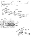
- Figures 6 through 9 pertain to additional embodiments wherein various additions, modifications, and/or alterations have been made to the basic sleeve shown in Figures 1 - 5 for the purposes of further facilitating its utility and/or permitting the use of non-slip dowel or rebar within a "grout tube" application.
- the basic slip dowel placement sleeve 10 of the invention comprises a generally cylindrical dowel receiving sheath 12 having a closed distal end 14, a preferrably open proximal end 16, and a hollow interior compartment formed therewithin.
- a generally rectangular flange 18 extends perpendicularly about the proximal end 16 of the sheath 12.
- a central aperture is formed in the flange 18 so as to permit passage of a dowel rod through the flange and into the open inner compartment of the sheath 12.
- Plural apertures 20, 22, 24, and 26 are formed near each corner of the flange 18 to permit nailing or stapling of the flange to the surface of a wooden concrete form or other surface.
- the sleeve 10 is integrally formed of a plastic material fabricated by conventional molding techniques.
- the attachment of the dowel rod placement apparatus, 10A, 10B, 10C, 10D to form 30 is made by passing staples or small head nails through the apertures 20, 22, 24, 26 of flanges 18A - D. Thereafter, the form 30 is held firmly in position by stakes 32, 34. A first concrete pour is made within the form 30 so as to form first concrete slab 36. After slab 36 has set, the form 30 is stripped away, separating the individual flanges, 18A - D and their associated nail or staple fasteners from the inner surface of the form 30. Such stripping away of the form 30 leaves the individual dowel rod positioning sleeves 10A - D in a parallel array within the slab 36 while the proximal flanges 18A - D thereof reside flush with the formed edge 38 of slab 36.
- Sections of smooth dowel 40, 41, 42 are then inserted through apertures located in flanges 18A - D and advanced distally into the longitudinal inner cavities of the dowel receiving sheaths of sheeves 10A - D.
- the portion of the dowel rods 40, 41, 42 advanced into the sleeves 10A - D will remain slidably disposed therein while the remaining portion of dowel rods 40, 41, 42 extend outwardly into an adjacent space 46 wherein a second concrete pour is to be made.
- a cold joint or seam 50 extends between the first slab 36 and the second slab 48.
- the dowel rod positioning sleeves 10A - D of the present invention the dowel rods 40, 41, 42 remain parallel to one another and longitudinally slidable within the first slab 36 while being firmly cured in place within second slab 48.
- the individual first 36 and second 48 slabs are permitted to undergo longitudinal expansion and contraction along the dowels 40, 41 and 42 while at the same time being prevented from buckling or undergoing vertical or angular displacement at the cold joint 50.
- the slip dowel positioning apparatus of the present invention may be configured so as to be "strippable" or extractable from the first concrete pour, thereby leaving an open cylindrical void within the first concrete slab, so as to permit insertion of the desired dowel rods without requiring continued presence of the dowel rod positioning apparatus.
- the extractable or "strippable" positioning apparatus 100 of the invention differs from the basic positioning apparatus 10 in that the outer surface of the dowel receiving sheath 120 of the extractable apparatus 100 is distally tapered such that the distal end 140 thereof is smaller than the proximal end 160.
- the proximal flange 180 of the extractable apparatus 100 is structurally the same as that of the basic apparatus 10 described in Figure 1.
- the provision of the tapered sheath 120 permits the extractable apparatus 100 to be pulled out of the first concrete slab automatically upon stripping of the form from the slab, thereby leaving an open cylindrical void within the slab.
- the extracted apparatus 100 may then be reused in subsequent concrete pours.
- the corrugated or ribbed "grout tube” 200 comprises a corrugated sheath 220 having a closed distal end 240 and an open proximal end 260 with a flange 280 positioned on the proximal end 260 in a manner substantially identical to that of the basic apparatus 10.
- this "grout tube” embodiment 200 differs from the basic placement sleeve 10 in that the sheath 220 of the “grout tube” is provided with a multiplicity of annular ribs 282 upon the outer surface of the sheath 220 and further forming indentations within the inner cavity thereof.
- Such corrugated or ribbed construction firmly holds the "grout tube” in a set position within the center of a concrete slab 360.
- a section of rebar 400 is inserted into the inner cavity of the apparatus with a quantity of conventional grouting material 402 being applied so as to fill the space therewithin. As the grouting material 402 hardens it serves to hold the rebar 400 firmly in place within the "grout tube” 200.
- the remaining portion of the rebar 400 extends into an adjoining open area where it becomes set within a poured second slab 480 such that the rebar will be firmly held within first slab 360 by way of the grouting material 402 and grout tube while the opposite end of the rebar is firmly held within a second poured concrete slab.
- first and second concrete slabs 360 and 480 are prevented from moving longitudinally as well as angularly along cold joint 500.
- a further modification of the basic device which is contemplated by the invention is the provision of fins or gussets 60 as shown in Figure 9.
- Such fins or gussets are of generally triangular configuration and extend between the proximal end 16 of the tubular sheath 12 and the inner surface of flange 18 so as to impart additional strength and rigidity to the apparatus.
- various other types of fins, gussetts, supports, or braces may be employed and, such fins need not be limited to the triangular configurations shown in Figure 9.
Landscapes
- Engineering & Computer Science (AREA)
- Architecture (AREA)
- General Engineering & Computer Science (AREA)
- Civil Engineering (AREA)
- Structural Engineering (AREA)
- Mechanical Engineering (AREA)
- Physics & Mathematics (AREA)
- Electromagnetism (AREA)
- Joining Of Building Structures In Genera (AREA)
- Forms Removed On Construction Sites Or Auxiliary Members Thereof (AREA)
- Slot Machines And Peripheral Devices (AREA)
- On-Site Construction Work That Accompanies The Preparation And Application Of Concrete (AREA)
Applications Claiming Priority (1)
| Application Number | Priority Date | Filing Date | Title |
|---|---|---|---|
| US07/508,080 US5005331A (en) | 1990-04-10 | 1990-04-10 | Concrete dowel placement sleeves |
Publications (2)
| Publication Number | Publication Date |
|---|---|
| EP0489988A1 true EP0489988A1 (fr) | 1992-06-17 |
| EP0489988B1 EP0489988B1 (fr) | 1997-03-05 |
Family
ID=24021304
Family Applications (1)
| Application Number | Title | Priority Date | Filing Date |
|---|---|---|---|
| EP90312427A Expired - Lifetime EP0489988B1 (fr) | 1990-04-10 | 1990-11-14 | Positionnement de douilles pour boulons dans des constructions en beton |
Country Status (7)
| Country | Link |
|---|---|
| US (1) | US5005331A (fr) |
| EP (1) | EP0489988B1 (fr) |
| AT (1) | ATE149596T1 (fr) |
| DE (1) | DE69030094T2 (fr) |
| DK (1) | DK0489988T3 (fr) |
| ES (1) | ES2101692T3 (fr) |
| GR (1) | GR3023671T3 (fr) |
Cited By (2)
| Publication number | Priority date | Publication date | Assignee | Title |
|---|---|---|---|---|
| EP0773324B1 (fr) * | 1995-11-07 | 1998-07-22 | F.J. Aschwanden AG | Dispositif pour la connection et la transmission des forces transversales entre deux structures séparées par un joint |
| GB2450709A (en) * | 2007-07-04 | 2009-01-07 | Structural Systems Uk Ltd | Fixing slabs with a dowel and sleeve arrangement |
Families Citing this family (91)
| Publication number | Priority date | Publication date | Assignee | Title |
|---|---|---|---|---|
| US5216862A (en) * | 1988-10-27 | 1993-06-08 | Shaw Ronald D | Concrete dowel placement sleeves |
| US5618125A (en) * | 1994-01-18 | 1997-04-08 | Permaban North America, Inc. | Dowell alignment apparatus |
| US5487249A (en) * | 1994-03-28 | 1996-01-30 | Shaw; Ronald D. | Dowel placement apparatus for monolithic concrete pour and method of use |
| AUPN333095A0 (en) * | 1995-06-05 | 1995-06-29 | Durack, Michael James | Concrete slab sockets |
| US5674028A (en) * | 1995-07-28 | 1997-10-07 | Norin; Kenton Neal | Doweled construction joint and method of forming same |
| US5678952A (en) * | 1995-11-16 | 1997-10-21 | Shaw; Lee A. | Concrete dowel placement apparatus |
| US6922968B1 (en) | 1997-07-18 | 2005-08-02 | Diane E. Miller | Accessory for building construction |
| US5813188A (en) * | 1997-07-18 | 1998-09-29 | Diane E. Miller | Accessory for building construction |
| US6449919B1 (en) | 1998-09-28 | 2002-09-17 | Diane E. Miller | Accessory for building construction |
| CH692991A5 (de) * | 1997-11-17 | 2003-01-15 | Pecon Ag | Querkraftdornlagerung. |
| US6354760B1 (en) | 1997-11-26 | 2002-03-12 | Russell Boxall | System for transferring loads between cast-in-place slabs |
| US6145262A (en) * | 1998-11-12 | 2000-11-14 | Expando-Lok, Inc. | Dowel bar sleeve system and method |
| USD419700S (en) * | 1998-11-20 | 2000-01-25 | Shaw Lee A | Load transfer dowel holder |
| USD459205S1 (en) | 1999-02-05 | 2002-06-25 | Lee A. Shaw | Concrete dowel tube with clip |
| US6210070B1 (en) | 1999-04-14 | 2001-04-03 | Ron D. Shaw | Concrete dowel slip tube with clip |
| US6502359B1 (en) | 2000-02-22 | 2003-01-07 | Bometals, Inc. | Dowel placement apparatus for concrete slabs |
| US6389774B1 (en) | 2001-02-13 | 2002-05-21 | Gregory Howard Carpenter | Pipe dowel for concrete slab construction |
| NZ531726A (en) * | 2001-09-13 | 2006-06-30 | Russell Boxall | Load transfer plate for in situ concrete slabs |
| US6645342B2 (en) | 2002-03-08 | 2003-11-11 | William M. Scott | Pull strip for forming holes |
| US20040079043A1 (en) * | 2002-03-08 | 2004-04-29 | Scott William M. | Pull strip for forming holes |
| US6692184B1 (en) | 2002-11-12 | 2004-02-17 | Meadow Burke Products | Retrofit dowel for maintaining concrete structures in alignment |
| US7004443B2 (en) * | 2003-03-19 | 2006-02-28 | Dayton Superior Corporation | Concrete void former |
| US6926463B2 (en) * | 2003-08-13 | 2005-08-09 | Lee A. Shaw | Disk plate concrete dowel system |
| US7338230B2 (en) * | 2003-08-13 | 2008-03-04 | Shaw & Sons, Inc. | Plate concrete dowel system |
| US7314333B2 (en) * | 2003-08-13 | 2008-01-01 | Shaw & Sons, Inc. | Plate concrete dowel system |
| US20060275078A1 (en) * | 2003-08-13 | 2006-12-07 | Shaw & Sons, Inc. | Plate concrete dowel system |
| US8454265B2 (en) | 2005-02-09 | 2013-06-04 | Ez Form, Inc. | Apparatus for transferring loads between concrete slabs |
| US20050166531A1 (en) * | 2005-02-09 | 2005-08-04 | Mcdonald Stephen F. | Method of forming concrete and an apparatus for transferring loads between concrete slabs |
| US20060185316A1 (en) * | 2005-02-09 | 2006-08-24 | Jordan Richard D | Apparatus for and method of forming concrete and transferring loads between concrete slabs |
| US20060180950A1 (en) * | 2005-02-09 | 2006-08-17 | Jordan Richard D | Apparatus for and method of forming concrete and transferring loads between concrete slabs |
| US7201535B2 (en) | 2005-02-10 | 2007-04-10 | Kramer Donald R | Concrete slab dowel system and method for making and using same |
| US7441984B2 (en) * | 2005-02-10 | 2008-10-28 | Kramer Donald R | Concrete slab dowel system and method for making and using same |
| US20070272824A1 (en) * | 2005-03-11 | 2007-11-29 | Mcdonald Stephen F | Method of Forming Concrete |
| US7637689B2 (en) * | 2005-08-11 | 2009-12-29 | Russell Boxall | On-grade plates for joints between on-grade concrete slabs |
| US20070134063A1 (en) * | 2005-12-14 | 2007-06-14 | Shaw And Sons, Inc. | Dowel device with closed end speed cover |
| US20070196170A1 (en) * | 2006-02-09 | 2007-08-23 | Mcdonald Stephen F | Apparatus for forming concrete and transferring loads between concrete slabs |
| US20070231068A1 (en) * | 2006-03-29 | 2007-10-04 | Mmi Management Services, Lp | Pocket assembly for placing a flat dowel between cast in place concrete slabs |
| US7441985B2 (en) * | 2006-05-17 | 2008-10-28 | Mmi Management Services Lp | Method and apparatus for providing a dowell connection to maintain cast-in-place concrete slabs in alignment |
| US7736088B2 (en) * | 2006-07-13 | 2010-06-15 | Russell Boxall | Rectangular load plate |
| US20080263969A1 (en) * | 2007-01-30 | 2008-10-30 | David Poulis | Vapor & moisture resistant carrier apparatus |
| US7748928B2 (en) * | 2007-07-31 | 2010-07-06 | Greenstreak Group, Inc. | Concrete slab joint system including a load plate sleeve |
| US7905680B2 (en) * | 2007-09-05 | 2011-03-15 | Steve Albritton | Concrete dowel placement device and methods of use |
| DE102009001749B4 (de) * | 2009-03-23 | 2011-05-19 | Hilti Aktiengesellschaft | Anschlussvorrichtung und Verfahren zur Erstellung eines Anschlusses |
| US8291662B2 (en) | 2010-01-06 | 2012-10-23 | Tdj Masonry Inc. | Continuous pour concrete slip dowel |
| USD635278S1 (en) * | 2010-03-23 | 2011-03-29 | Actuant Corporation | Portion of a concrete anchor |
| US8627626B2 (en) * | 2010-04-21 | 2014-01-14 | Russell Boxall | Transferring loads across joints in concrete slabs |
| US8496398B2 (en) | 2010-06-14 | 2013-07-30 | Michael DiPietro | Rebar sleeve unit |
| US9469994B2 (en) * | 2012-08-14 | 2016-10-18 | Stephen Boyd | Embedded dowel inserts |
| CN105143574B (zh) * | 2013-03-27 | 2018-06-29 | 韦森多夫系统涂料有限公司 | 用于将脚手架固定在建筑物壁上的结构系统和方法 |
| US10100511B2 (en) * | 2013-08-12 | 2018-10-16 | Stephen Boyd | Embedded dowel inserts with dowel retention mechanisms and dowel insert tube extenders |
| US20150121797A1 (en) * | 2013-11-06 | 2015-05-07 | Chad Brown | Concrete anchor |
| US20150197898A1 (en) | 2014-01-15 | 2015-07-16 | Shaw & Sons, Inc. | Concrete dowel system |
| NO337777B1 (no) * | 2014-03-03 | 2016-06-20 | Svein Berg Holding As | En jordskjelvbestandig bygningsforbindelse og et jordskjelvbestandig trappesystem. |
| US9340969B1 (en) | 2014-11-13 | 2016-05-17 | Shaw & Sons, Inc. | Crush zone dowel tube |
| AU2016265037B2 (en) * | 2015-05-19 | 2020-03-05 | Lifting Point Pre-Form Pty Limited | A clip |
| US20190024367A1 (en) | 2015-10-05 | 2019-01-24 | Shaw & Sons, Inc. | Concrete dowel placement system and method of making the same |
| US20170096810A1 (en) | 2015-10-05 | 2017-04-06 | Shaw & Sons, Inc. | Concrete dowel placement system and method of making the same |
| US10077551B2 (en) | 2015-10-05 | 2018-09-18 | Illinois Tool Works Inc. | Joint edge assembly and method for forming joint in offset position |
| US10119281B2 (en) | 2016-05-09 | 2018-11-06 | Illinois Tool Works Inc. | Joint edge assembly and formwork for forming a joint, and method for forming a joint |
| USD844415S1 (en) * | 2016-07-25 | 2019-04-02 | Mark V Kneib | Concrete spacer |
| US10590643B2 (en) | 2016-11-16 | 2020-03-17 | Illinois Tool Works Inc. | Load transfer plate and load transfer plate pocket and method of employing same |
| US10323406B2 (en) | 2017-01-16 | 2019-06-18 | Midwest Concrete & Masonry Supply, Inc. | Floor dowel sleeve for concrete slab seams |
| US11174614B2 (en) * | 2017-08-14 | 2021-11-16 | Contech Engineered Solutions LLC | Metal foundation system for culverts, buried bridges and other structures |
| AU2018226392B2 (en) | 2017-10-13 | 2024-10-10 | Illinois Tool Works Inc. | Edge protection system having dowel plate |
| AU2018226391B2 (en) | 2017-10-13 | 2024-10-10 | Illinois Tool Works Inc. | Edge protection system having support foot |
| AU2018226390B2 (en) | 2017-10-13 | 2024-09-19 | Illinois Tool Works Inc. | Edge protection system having retaining clip |
| AU2018226389B2 (en) | 2017-10-13 | 2024-09-12 | Illinois Tool Works Inc. | Edge protection system having bridging pins |
| AU2018226394B2 (en) | 2017-10-13 | 2024-09-12 | Illinois Tool Works Inc. | Edge protection system having clip retainment |
| AU2018226393B2 (en) * | 2017-10-13 | 2024-09-26 | Illinois Tool Works Inc. | Edge protection system with intersection module |
| USD850896S1 (en) * | 2017-12-19 | 2019-06-11 | Shaw & Sons, Inc. | Dowel tube |
| US10662642B2 (en) | 2018-04-03 | 2020-05-26 | Midwest Concrete & Masonry Supply, Inc. | Floor dowel sleeve with integral spacing chambers |
| AU2019264633B2 (en) | 2018-11-19 | 2025-08-07 | Illinois Tool Works Inc. | Support bracket |
| EP4010538B1 (fr) | 2019-08-05 | 2026-03-18 | Hickory Design Pty Ltd | Panneau de construction préfabriqué |
| USD919224S1 (en) | 2019-12-20 | 2021-05-11 | Illinois Tool Works Inc. | Load transfer plate pocket internal bracing insert |
| USD922719S1 (en) | 2019-12-20 | 2021-06-15 | Illinois Tool Works Inc. | Load transfer plate pocket |
| US11041318B1 (en) | 2019-12-20 | 2021-06-22 | Illinois Tool Works Inc. | Load transfer plate apparatus |
| US11578491B2 (en) | 2020-02-07 | 2023-02-14 | Shaw Craftsmen Concrete, Llc | Topping slab installation methodology |
| US20210292978A1 (en) | 2020-03-17 | 2021-09-23 | Shaw Craftsmen Concrete, Llc | Concrete dowel placement method and apparatus |
| DE202021000466U1 (de) * | 2021-02-01 | 2021-04-22 | Halfen Gmbh | Einrichtung zur nachträglichen thermisch isolierenden, kraftübertragenden Anbindung eines zweiten lastaufnehmenden Bauwerksteils an ein erstes lastaufnehmendes Bauwerksteil und Bauwerk mit einer solchen Einrichtung |
| AU2021204992A1 (en) | 2021-07-12 | 2023-02-02 | Illinois Tool Works Inc. | An armoured joint – disruptive folded anchor rail |
| AU2021204993A1 (en) | 2021-07-12 | 2023-02-02 | Illinois Tool Works Inc. | An edge protection system – floating cover plate on intersection |
| AU2021204994A1 (en) | 2021-07-12 | 2023-02-02 | Illinois Tool Works Inc. | An edge protection system – intersection continuous perimeter joint line |
| AU2021204996A1 (en) | 2021-07-12 | 2023-02-02 | Illinois Tool Works Inc. | An armoured joint – anti-skew stake bracket |
| AU2021204995A1 (en) | 2021-07-12 | 2023-02-02 | Illinois Tool Works Inc. | An edge protection system – joint orientation marker |
| AU2021221651A1 (en) * | 2021-08-25 | 2023-03-16 | Illinois Tool Works Inc. | Dowel system |
| AU2023200089A1 (en) | 2022-04-01 | 2023-10-19 | Illinois Tool Works Inc. | Concrete slab joint forming system and method |
| WO2024059738A1 (fr) * | 2022-09-14 | 2024-03-21 | Wilian Holding Co. | Attaches coniques pour coffrage en béton et dispositifs, systèmes et procédés associés |
| USD1081343S1 (en) | 2022-09-30 | 2025-07-01 | Illinois Tool Works Inc. | Joint former intersection |
| USD1050873S1 (en) * | 2022-09-30 | 2024-11-12 | Illinois Tool Works Inc. | Joint former connector |
| USD1063119S1 (en) | 2022-09-30 | 2025-02-18 | Illinois Tool Works Inc. | Joint former |
| USD1056696S1 (en) * | 2023-01-19 | 2025-01-07 | Performance Delivery Incorporated | Anchor |
Citations (3)
| Publication number | Priority date | Publication date | Assignee | Title |
|---|---|---|---|---|
| BE831180A (fr) * | 1975-07-09 | 1975-11-03 | Accessoire de coffrage d'elements de revetement fabriques in situ, assurant leur solidarisation mutuelle tout en permettant leur deplacement relatif | |
| EP0032105B1 (fr) * | 1980-01-04 | 1987-05-20 | Ulisse C. Aschwanden | Broche et douille pour la liaison d'éléments de construction en génie civil |
| EP0328484A1 (fr) * | 1988-02-11 | 1989-08-16 | Egco Ag | Manchon de glissement pour la prise d'un boulon de force transversal |
Family Cites Families (5)
| Publication number | Priority date | Publication date | Assignee | Title |
|---|---|---|---|---|
| US1045562A (en) * | 1911-12-28 | 1912-11-26 | Joseph Kennedy | Concrete insert. |
| US2636426A (en) * | 1946-09-18 | 1953-04-28 | The Union Savings Trus Company | Dowel bar adjusting and aligning device |
| US2746365A (en) * | 1951-11-16 | 1956-05-22 | Joseph A Darneille | Road construction |
| DE3460289D1 (en) * | 1983-03-16 | 1986-08-21 | Witschi H | Connection and stress repartition element for concrete parts |
| US4533112A (en) * | 1983-10-11 | 1985-08-06 | Western Steel Cutting, Inc. | Curb stake with integral support |
-
1990
- 1990-04-10 US US07/508,080 patent/US5005331A/en not_active Expired - Lifetime
- 1990-11-14 AT AT90312427T patent/ATE149596T1/de not_active IP Right Cessation
- 1990-11-14 DE DE69030094T patent/DE69030094T2/de not_active Expired - Fee Related
- 1990-11-14 EP EP90312427A patent/EP0489988B1/fr not_active Expired - Lifetime
- 1990-11-14 ES ES90312427T patent/ES2101692T3/es not_active Expired - Lifetime
- 1990-11-14 DK DK90312427.9T patent/DK0489988T3/da active
-
1997
- 1997-06-04 GR GR970401315T patent/GR3023671T3/el unknown
Patent Citations (3)
| Publication number | Priority date | Publication date | Assignee | Title |
|---|---|---|---|---|
| BE831180A (fr) * | 1975-07-09 | 1975-11-03 | Accessoire de coffrage d'elements de revetement fabriques in situ, assurant leur solidarisation mutuelle tout en permettant leur deplacement relatif | |
| EP0032105B1 (fr) * | 1980-01-04 | 1987-05-20 | Ulisse C. Aschwanden | Broche et douille pour la liaison d'éléments de construction en génie civil |
| EP0328484A1 (fr) * | 1988-02-11 | 1989-08-16 | Egco Ag | Manchon de glissement pour la prise d'un boulon de force transversal |
Cited By (2)
| Publication number | Priority date | Publication date | Assignee | Title |
|---|---|---|---|---|
| EP0773324B1 (fr) * | 1995-11-07 | 1998-07-22 | F.J. Aschwanden AG | Dispositif pour la connection et la transmission des forces transversales entre deux structures séparées par un joint |
| GB2450709A (en) * | 2007-07-04 | 2009-01-07 | Structural Systems Uk Ltd | Fixing slabs with a dowel and sleeve arrangement |
Also Published As
| Publication number | Publication date |
|---|---|
| DE69030094D1 (de) | 1997-04-10 |
| ATE149596T1 (de) | 1997-03-15 |
| DE69030094T2 (de) | 1997-08-28 |
| EP0489988B1 (fr) | 1997-03-05 |
| DK0489988T3 (da) | 1997-08-25 |
| GR3023671T3 (en) | 1997-09-30 |
| ES2101692T3 (es) | 1997-07-16 |
| US5005331A (en) | 1991-04-09 |
Similar Documents
| Publication | Publication Date | Title |
|---|---|---|
| US5005331A (en) | Concrete dowel placement sleeves | |
| US5216862A (en) | Concrete dowel placement sleeves | |
| US5934821A (en) | Concrete dowel placement apparatus | |
| US5487249A (en) | Dowel placement apparatus for monolithic concrete pour and method of use | |
| US8007199B2 (en) | Dowel device with closed end speed cover | |
| US12601168B2 (en) | Concrete dowel placement system and method of making the same | |
| US12059832B2 (en) | Concrete dowel placement system and method of making the same | |
| US7887735B2 (en) | Method of forming a void in a mass of concrete using a dowel void former | |
| WO1996039564A1 (fr) | Culot pour dalles de beton | |
| US5618125A (en) | Dowell alignment apparatus | |
| US20140248076A1 (en) | Slip dowel system | |
| US7905680B2 (en) | Concrete dowel placement device and methods of use | |
| US20230151559A1 (en) | Concrete dowel placement method and apparatus | |
| US6256962B1 (en) | Tie for reusable form panels | |
| CA2029922C (fr) | Douilles pour le positionnement de goujons dans le beton | |
| JPH04277232A (ja) | コンクリートダボ配置装置 | |
| AU2003100995A4 (en) | Fastener Devices | |
| CA2237651A1 (fr) | Appareil de positionnement de goujon a beton | |
| JPH0656403U (ja) | パイプ材の仮止装置 | |
| GB2141773A (en) | Replacement wall ties | |
| AU5805896A (en) | Concrete slab sockets |
Legal Events
| Date | Code | Title | Description |
|---|---|---|---|
| PUAI | Public reference made under article 153(3) epc to a published international application that has entered the european phase |
Free format text: ORIGINAL CODE: 0009012 |
|
| AK | Designated contracting states |
Kind code of ref document: A1 Designated state(s): AT BE CH DE DK ES FR GB GR IT LI LU NL SE |
|
| 17P | Request for examination filed |
Effective date: 19921207 |
|
| 17Q | First examination report despatched |
Effective date: 19940126 |
|
| GRAG | Despatch of communication of intention to grant |
Free format text: ORIGINAL CODE: EPIDOS AGRA |
|
| GRAH | Despatch of communication of intention to grant a patent |
Free format text: ORIGINAL CODE: EPIDOS IGRA |
|
| GRAH | Despatch of communication of intention to grant a patent |
Free format text: ORIGINAL CODE: EPIDOS IGRA |
|
| GRAA | (expected) grant |
Free format text: ORIGINAL CODE: 0009210 |
|
| AK | Designated contracting states |
Kind code of ref document: B1 Designated state(s): AT BE CH DE DK ES FR GB GR IT LI LU NL SE |
|
| REF | Corresponds to: |
Ref document number: 149596 Country of ref document: AT Date of ref document: 19970315 Kind code of ref document: T |
|
| REG | Reference to a national code |
Ref country code: CH Ref legal event code: EP |
|
| REF | Corresponds to: |
Ref document number: 69030094 Country of ref document: DE Date of ref document: 19970410 |
|
| ITF | It: translation for a ep patent filed | ||
| ET | Fr: translation filed | ||
| REG | Reference to a national code |
Ref country code: CH Ref legal event code: NV Representative=s name: CABINET ROLAND NITHARDT CONSEILS EN PROPRIETE INDU |
|
| REG | Reference to a national code |
Ref country code: ES Ref legal event code: FG2A Ref document number: 2101692 Country of ref document: ES Kind code of ref document: T3 |
|
| REG | Reference to a national code |
Ref country code: DK Ref legal event code: T3 |
|
| REG | Reference to a national code |
Ref country code: GR Ref legal event code: FG4A Free format text: 3023671 |
|
| PLBE | No opposition filed within time limit |
Free format text: ORIGINAL CODE: 0009261 |
|
| STAA | Information on the status of an ep patent application or granted ep patent |
Free format text: STATUS: NO OPPOSITION FILED WITHIN TIME LIMIT |
|
| 26N | No opposition filed | ||
| PGFP | Annual fee paid to national office [announced via postgrant information from national office to epo] |
Ref country code: SE Payment date: 20011106 Year of fee payment: 12 |
|
| PGFP | Annual fee paid to national office [announced via postgrant information from national office to epo] |
Ref country code: LU Payment date: 20011108 Year of fee payment: 12 |
|
| PGFP | Annual fee paid to national office [announced via postgrant information from national office to epo] |
Ref country code: FR Payment date: 20011113 Year of fee payment: 12 Ref country code: DK Payment date: 20011113 Year of fee payment: 12 Ref country code: AT Payment date: 20011113 Year of fee payment: 12 |
|
| PGFP | Annual fee paid to national office [announced via postgrant information from national office to epo] |
Ref country code: GB Payment date: 20011114 Year of fee payment: 12 |
|
| PGFP | Annual fee paid to national office [announced via postgrant information from national office to epo] |
Ref country code: ES Payment date: 20011122 Year of fee payment: 12 |
|
| PGFP | Annual fee paid to national office [announced via postgrant information from national office to epo] |
Ref country code: DE Payment date: 20011126 Year of fee payment: 12 |
|
| PGFP | Annual fee paid to national office [announced via postgrant information from national office to epo] |
Ref country code: NL Payment date: 20011129 Year of fee payment: 12 Ref country code: GR Payment date: 20011129 Year of fee payment: 12 |
|
| PGFP | Annual fee paid to national office [announced via postgrant information from national office to epo] |
Ref country code: CH Payment date: 20011130 Year of fee payment: 12 |
|
| REG | Reference to a national code |
Ref country code: GB Ref legal event code: IF02 |
|
| PGFP | Annual fee paid to national office [announced via postgrant information from national office to epo] |
Ref country code: BE Payment date: 20020124 Year of fee payment: 12 |
|
| PG25 | Lapsed in a contracting state [announced via postgrant information from national office to epo] |
Ref country code: LU Free format text: LAPSE BECAUSE OF NON-PAYMENT OF DUE FEES Effective date: 20021114 Ref country code: GB Free format text: LAPSE BECAUSE OF NON-PAYMENT OF DUE FEES Effective date: 20021114 Ref country code: AT Free format text: LAPSE BECAUSE OF NON-PAYMENT OF DUE FEES Effective date: 20021114 |
|
| PG25 | Lapsed in a contracting state [announced via postgrant information from national office to epo] |
Ref country code: SE Free format text: LAPSE BECAUSE OF NON-PAYMENT OF DUE FEES Effective date: 20021115 Ref country code: ES Free format text: LAPSE BECAUSE OF NON-PAYMENT OF DUE FEES Effective date: 20021115 |
|
| PG25 | Lapsed in a contracting state [announced via postgrant information from national office to epo] |
Ref country code: LI Free format text: LAPSE BECAUSE OF NON-PAYMENT OF DUE FEES Effective date: 20021130 Ref country code: CH Free format text: LAPSE BECAUSE OF NON-PAYMENT OF DUE FEES Effective date: 20021130 Ref country code: BE Free format text: LAPSE BECAUSE OF NON-PAYMENT OF DUE FEES Effective date: 20021130 |
|
| PG25 | Lapsed in a contracting state [announced via postgrant information from national office to epo] |
Ref country code: DK Free format text: LAPSE BECAUSE OF NON-PAYMENT OF DUE FEES Effective date: 20021231 |
|
| BERE | Be: lapsed |
Owner name: *SHAW LEE A. Effective date: 20021130 Owner name: *SHAW LEROY E. Effective date: 20021130 Owner name: *SHAW RONALD D. Effective date: 20021130 |
|
| PG25 | Lapsed in a contracting state [announced via postgrant information from national office to epo] |
Ref country code: NL Free format text: LAPSE BECAUSE OF NON-PAYMENT OF DUE FEES Effective date: 20030601 |
|
| PG25 | Lapsed in a contracting state [announced via postgrant information from national office to epo] |
Ref country code: DE Free format text: LAPSE BECAUSE OF NON-PAYMENT OF DUE FEES Effective date: 20030603 |
|
| PG25 | Lapsed in a contracting state [announced via postgrant information from national office to epo] |
Ref country code: GR Free format text: LAPSE BECAUSE OF NON-PAYMENT OF DUE FEES Effective date: 20030609 |
|
| EUG | Se: european patent has lapsed | ||
| GBPC | Gb: european patent ceased through non-payment of renewal fee | ||
| REG | Reference to a national code |
Ref country code: DK Ref legal event code: EBP |
|
| REG | Reference to a national code |
Ref country code: CH Ref legal event code: PL |
|
| PG25 | Lapsed in a contracting state [announced via postgrant information from national office to epo] |
Ref country code: FR Free format text: LAPSE BECAUSE OF NON-PAYMENT OF DUE FEES Effective date: 20030731 |
|
| NLV4 | Nl: lapsed or anulled due to non-payment of the annual fee |
Effective date: 20030601 |
|
| REG | Reference to a national code |
Ref country code: FR Ref legal event code: ST |
|
| REG | Reference to a national code |
Ref country code: ES Ref legal event code: FD2A Effective date: 20031213 |
|
| PG25 | Lapsed in a contracting state [announced via postgrant information from national office to epo] |
Ref country code: IT Free format text: LAPSE BECAUSE OF NON-PAYMENT OF DUE FEES;WARNING: LAPSES OF ITALIAN PATENTS WITH EFFECTIVE DATE BEFORE 2007 MAY HAVE OCCURRED AT ANY TIME BEFORE 2007. THE CORRECT EFFECTIVE DATE MAY BE DIFFERENT FROM THE ONE RECORDED. Effective date: 20051114 |