EP0489997B1 - Turbine améliorée à courant axial - Google Patents
Turbine améliorée à courant axial Download PDFInfo
- Publication number
- EP0489997B1 EP0489997B1 EP90313597A EP90313597A EP0489997B1 EP 0489997 B1 EP0489997 B1 EP 0489997B1 EP 90313597 A EP90313597 A EP 90313597A EP 90313597 A EP90313597 A EP 90313597A EP 0489997 B1 EP0489997 B1 EP 0489997B1
- Authority
- EP
- European Patent Office
- Prior art keywords
- blade
- end portion
- tip end
- thickness
- root end
- Prior art date
- Legal status (The legal status is an assumption and is not a legal conclusion. Google has not performed a legal analysis and makes no representation as to the accuracy of the status listed.)
- Expired - Lifetime
Links
- 238000011144 upstream manufacturing Methods 0.000 claims description 5
- 230000007423 decrease Effects 0.000 claims description 3
- 239000000463 material Substances 0.000 description 4
- 238000004519 manufacturing process Methods 0.000 description 3
- 238000002485 combustion reaction Methods 0.000 description 1
- 238000010276 construction Methods 0.000 description 1
- 238000001816 cooling Methods 0.000 description 1
- 239000002991 molded plastic Substances 0.000 description 1
Images
Classifications
-
- F—MECHANICAL ENGINEERING; LIGHTING; HEATING; WEAPONS; BLASTING
- F04—POSITIVE - DISPLACEMENT MACHINES FOR LIQUIDS; PUMPS FOR LIQUIDS OR ELASTIC FLUIDS
- F04D—NON-POSITIVE-DISPLACEMENT PUMPS
- F04D29/00—Details, component parts, or accessories
- F04D29/26—Rotors specially for elastic fluids
- F04D29/32—Rotors specially for elastic fluids for axial flow pumps
- F04D29/38—Blades
-
- F—MECHANICAL ENGINEERING; LIGHTING; HEATING; WEAPONS; BLASTING
- F04—POSITIVE - DISPLACEMENT MACHINES FOR LIQUIDS; PUMPS FOR LIQUIDS OR ELASTIC FLUIDS
- F04D—NON-POSITIVE-DISPLACEMENT PUMPS
- F04D29/00—Details, component parts, or accessories
- F04D29/26—Rotors specially for elastic fluids
- F04D29/32—Rotors specially for elastic fluids for axial flow pumps
- F04D29/325—Rotors specially for elastic fluids for axial flow pumps for axial flow fans
- F04D29/326—Rotors specially for elastic fluids for axial flow pumps for axial flow fans comprising a rotating shroud
-
- F—MECHANICAL ENGINEERING; LIGHTING; HEATING; WEAPONS; BLASTING
- F04—POSITIVE - DISPLACEMENT MACHINES FOR LIQUIDS; PUMPS FOR LIQUIDS OR ELASTIC FLUIDS
- F04D—NON-POSITIVE-DISPLACEMENT PUMPS
- F04D29/00—Details, component parts, or accessories
- F04D29/26—Rotors specially for elastic fluids
- F04D29/32—Rotors specially for elastic fluids for axial flow pumps
- F04D29/38—Blades
- F04D29/384—Blades characterised by form
-
- F—MECHANICAL ENGINEERING; LIGHTING; HEATING; WEAPONS; BLASTING
- F04—POSITIVE - DISPLACEMENT MACHINES FOR LIQUIDS; PUMPS FOR LIQUIDS OR ELASTIC FLUIDS
- F04D—NON-POSITIVE-DISPLACEMENT PUMPS
- F04D29/00—Details, component parts, or accessories
- F04D29/26—Rotors specially for elastic fluids
- F04D29/32—Rotors specially for elastic fluids for axial flow pumps
- F04D29/38—Blades
- F04D29/384—Blades characterised by form
- F04D29/386—Skewed blades
Definitions
- the present invention particularly concerns an axial flow air impeller for automotive radiator, heat exchanger use and the like and of the kind comprising a hub adapted for rotation about an axis and carrying a plurality of integrally formed similar circumaxially spaced and generally radially outwardly projecting air moving blades, each of the blades having a root end portion integral with the hub and a radially outwardly disposed tip end portion with smoothly curving side edges therebetween, the air impeller being adapted for unidirectional rotation in a forward direction and the side edges comprising leading and trailing edges the former of which curves substantially forwardly when viewed from root end portion to tip end portion to provide a projected width of each blade which is at least 40% greater at the tip end portion than at the root end portion; each blade having a maximum thickness which varies from a maximum at the root end portion and the maximum thickness at the tip end portion being at least three times the thickness at the blade trailing edge, and wherein an orifice ring is integral with each blade tip end portion and circumscribes the plurality of blades
- each blade is approximately 40% to 80% wider than the root end portion thereof.
- the orifice ring may be formed to be approximately bell mouthed as illustrated at its upstream or downstream end.
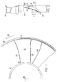
- Figure 1 is a fragmentary rear view of an improved axial flow air impeller constructed in accordance with the present invention.
- Figure 2 is a fragmentary side view of the air impeller of Figure 1.
- a hub is partially shown and indicated generally by the reference numeral 10 ⁇ .
- the hub 10 ⁇ may be rotated by on output shaft of an electric motor, a belt drive from an internal combustion engine etc., and serves to support and rotate a plurality of air moving blades.
- An air moving blade 12 is illustrated at 12 and a second air moving blade is partially illustrated at 12a.
- the air impeller shown is provided with nine (9) identical blades equally spaced circumaxially and each blade projects radially outwardly from the hub 10 ⁇ .
- the impeller is of molded plastic construction and the hub 10 ⁇ and blades 12 are formed integrally. That is, a root end portion of each blade 12 is formed integrally with the hub 10 ⁇ and the blade projects generally radially outwardly from the hub to its termination 18.
- a root end portion of the blade 12 is illustrated at 14 and, as best shown in Fig. 2, the root end portion 14 of the blade 12 is inclined or arranged at an angle of "pitch" relative to an axis of rotation 16. As will be apparent in Fig. 2, blade "pitch" decreases from the root end portion to the tip end portion 18 of the blade 12.
- the blade 12 has smoothly curved side edges extending between its root end portion 14 and its tip end portion 18 and, more particularly, the blade has a leading edge 20 ⁇ and a trailing edge 22.
- the air impeller of the present invention is unidirectional and rotates in a counterclockwise direction as illustrated in Fig. 1 by the directional arrow 24.
- each blade 12 of the impeller of the present invention is curved substantially forwardly when viewed from root end portion to tip end portion and the width of each blade is thus increased substantially in progression from the root end portion to the tip end portion. That is, the trailing edge of each blade 12 is preferably at least approximately radial as illustrated in Fig. 1 such that a substantial increase in blade width or "chord” occurs as a result of the forward sweep of the blade leading edge 20 ⁇ . Preferably, at least a 40 ⁇ % increase in blade projected width occurs throughout blade length and, as illustrated, the blade is substantially twice as wide at its tip end portion as at its root end portion thus showing a 10 ⁇ 0 ⁇ % increase in width.
- the forward sweep of the leading edge of the blade preferably occurs at a radially outwardly disposed portion thereof.
- the major portion of the forward curve at the leading edge of each blade preferably occurs at the outer one-half of the blade length measured from the root end portion to the tip end portion and, more specifically, at the outer one-third of the blade length so measured.
- the forward sweep of the leading edge of each of the blades 12 substantially improves the time incidence differential for radial points along the outer portion of the blade leading edge. This results in a significant reduction in noise generation.
- a significant variation in thickness occurs as the blade progresses from its root end portion 14 to its tip end portion 18, the thickness of the blade being substantially reduced.
- the thickness variation is designed to minimize stress in the blades and at the same time reduce to the extent possible the amount of material required to make the blade relative to a uniform thickness blade of the same strength.
- the value of x is selected as above falling between 1.0 ⁇ and 0 ⁇ .5 as indicated.
- the limit of three times the thickness of the blade edge is desirable but a limit of four times blade edge thickness is regarded as well within the scope of the invention.
- the blade mid-chord points are gradually shifted forwardly in progression from the root end portion of the blade to the tip end portion by the forward sweep of the blade leading edge.
- the dimension x shown in Fig. 2 may represent an approximate overall forward shift of the blade mid-chord point from the root end portion of the blade to the tip end portion thereof.
- the improved air impeller is provided with an orifice ring partially shown at 26.
- the orifice ring 26 includes a flange at one end thereof which forms a smooth radius with the remaining part of the ring.
- the ring 26 is formed integrally with the outer end portion 18 of the blade 12 and is similarly formed with the remaining nine blades of the impeller so as to circumscribe the plurality of blades forming the impeller.
- the impeller has upstream and downstream edges or ends and the upstream or downstream edge or end thereof is at least approximately bell mouthed. This of course serves to provide for a smooth flow of air into or from the fan blades and tends to prevent blade to blade leakage of air around the tips of the blades.
- the outer surface of the orifice ring may be contoured to match an associated housing or other opening in which the impeller is mounted. Clearance employed between the moving and stationary surfaces at the outer diameter of the ring can be provided at normal manufacturing tolerances found in high volume commercial applications. With this arrangement a better air seal is achieved than can be obtained using a conventional air impeller design without an orifice ring but employing very tight running tolerances. That is, a clearance of 0 ⁇ .10 ⁇ inches (0.254 cms) with the ring will match a clearance of 0 ⁇ .0 ⁇ 0 ⁇ 5 inches (0.013 cms) without a ring.
- the improved axial flow air impeller of the present invention provides for very low operating noise, maximum aerodynamic efficiency, improved mechanical strength and minimum material usage in manufacture.
- the thickness variation minimizes stress in the blades and at the same time reduces the amount of material required to make the blades.
- the addition of the orifice ring provides lateral stiffness to the impeller blades which accommodates the relatively thin blade sections, this in addition to the primary function of the orifice ring in reducing blade tip leakage.
- the reduction in blade tip leakage contributes directly to higher aerodynamic efficiency and the resulting decrease in flow disturbance around the blade tips serve still further to reduce noise generation.
Landscapes
- Engineering & Computer Science (AREA)
- Mechanical Engineering (AREA)
- General Engineering & Computer Science (AREA)
- Structures Of Non-Positive Displacement Pumps (AREA)
Claims (6)
- Turbine à flux axial pour radiateur d'auto-mobile, utilisation d'échangeur de chaleur et analogues, comprenant un moyen (10) destiné à tourner autour d'un axe (16) et portant une pluralité d'ailettes d'entraînement d'air formées d'un seul tenant à des espacements circonférentiels égaux et faisant saillie généralement radialement vers l'extérieur (12, 12a), chacune de ces ailettes comportant une partie d'extrémité d'encrage (14) faisant corps avec le moyeu (10) et une partie d'embout distal (18) s'étendant radialement vers l'extérieur, avec des bords latéraux s'incurvant doucement entre les deux arêtes (20, 22), cette turbine à air étant adaptée à tourner unidirectionnellement dans la direction avant (24) et les arêtes latérales comprenant une arête avant (20) et une arête arrière (22) dont le premier s'incurve essentiellement vers l'avant lorsqu'il est vu de la partie d'extrémité d'encrage (14) vers la partie d'embout distal (18), de manière à donner une largeur projetée de chaque ailette qui est supérieure d'au moins 40 % à la partie d'embout (18) par rapport à la partie d'extrémité d'encrage (14); chaque ailette ayant une épaisseur maximum qui varie à partir d'un maximum à la partie d'extrémité d'encrage (14), et l'épaisseur maximum à la partie d'extrémité d'embout (18) étant d'au moins le triple de l'épaisseur à l'endroit de l'arête arrière (22) de l'ailette ; un anneau d'orifice (26) faisant corps avec chaque partie d'extrémité d'embout d'ailette (18) et circonscrivant la pluralité d'ailettes (12, 12a), cet anneau (26) comportant une extrémité amont et une extrémité aval et représentant à une extrémité une collerette formant un rayon essentiellement lisse à la jonction avec la partie d'anneau, caractérisée en ce que l'épaisseur de chaque ailette se réduit lorsqu'on avance à partir de sa partie d'extrémité d'encrage (14), jusqu'à une épaisseur minimum à sa partie d'extrémité d'embout (18), cette réduction étant déterminée de façon que l'épaisseur d'ailette maximum à l'endroit d'une section d'ailette quelconque soit:
 Ts = épaisseur d'ailette à la section mesurée sTmax = épaisseur d'ailette maximum au voisinage de la partie d'extrémité d'encragers = rapport de rayons x à la section sencrage = rayon de la section à l'extrémité d'encrage de l'ailettex = entre 1,0 et 0,5 (valeur affectée de façon que la valeur minimum de Ts ne soit pas inférieure à trois fois l'épaisseur à l'endroit de l'arête arrière de l'ailette).
 - Turbine à flux axial selon la revendication 1, caractérisée en ce que les arêtes arrière (22) des ailettes s'étendent au moins approximativement le long de lignes radiales de façon que les points à mi-corde des ailettes soient progressivement déplacés vers l'avant lorsqu'on va de la partie d'extrémité d'encrage (14) vers la partie d'extrémité d'embout (18) sous l'effet de balayage vers l'avant des arêtes avant (20) des ailettes.
- Turbine à flux axial selon l'une quelconque des revendications 1 ou 2, caractérisée en ce que la courbe vers l'avant de chaque arête d'ailette avant (20) est telle que la largeur d'ailette soit supérieure d'environ 40 % à 80 % à la partie d'extrémité de l'embout (18), par rapport à la partie d'extrémité d'encrage (14).
- Turbine à flux axial selon l'une quelconque des revendications précédentes, caractérisée en ce que la partie d'extrémité d'encrage (14) de chaque ailette est disposée sous un certain angle de pas par rapport à l'axe (16), et en ce que cet angle de pas diminue de la partie d'extrémité d'encrage (14) vers la partie d'extrémité de l'embout (18) de l'ailette.
- Turbine à flux axial selon l'une quelconque des revendications précédentes, caractérisée en ce que la majeure partie de la courbe vers l'avant à l'endroit de l'arête avant (20) de chaque ailette, se trouve à la moitié extérieure de l'ailette mesurée depuis la partie d'extrémité d'encrage (14) vers la partie d'extrémité de l'embout (18).
- Turbine à flux axial selon la revendication 5, caractérisée en ce que la majeure partie de la courbe vers l'avant à l'endroit de l'arête avant de chaque ailette, se trouve au tiers extérieur de l'ailette mesuré depuis la partie d'extrémité d'encrage (14) vers la partie d'extrémité de l'embout (18).
Priority Applications (2)
| Application Number | Priority Date | Filing Date | Title |
|---|---|---|---|
| DE1990623657 DE69023657T2 (de) | 1990-12-13 | 1990-12-13 | Verbessertes Axialströmungsrad. |
| AT90313597T ATE130404T1 (de) | 1990-12-13 | 1990-12-13 | Verbessertes axialströmungsrad. |
Applications Claiming Priority (1)
| Application Number | Priority Date | Filing Date | Title |
|---|---|---|---|
| US07/408,744 US4995787A (en) | 1989-09-18 | 1989-09-18 | Axial flow impeller |
Publications (2)
| Publication Number | Publication Date |
|---|---|
| EP0489997A1 EP0489997A1 (fr) | 1992-06-17 |
| EP0489997B1 true EP0489997B1 (fr) | 1995-11-15 |
Family
ID=23617577
Family Applications (1)
| Application Number | Title | Priority Date | Filing Date |
|---|---|---|---|
| EP90313597A Expired - Lifetime EP0489997B1 (fr) | 1989-09-18 | 1990-12-13 | Turbine améliorée à courant axial |
Country Status (3)
| Country | Link |
|---|---|
| US (1) | US4995787A (fr) |
| EP (1) | EP0489997B1 (fr) |
| KR (1) | KR0120394B1 (fr) |
Families Citing this family (14)
| Publication number | Priority date | Publication date | Assignee | Title |
|---|---|---|---|---|
| US6194798B1 (en) | 1998-10-14 | 2001-02-27 | Air Concepts, Inc. | Fan with magnetic blades |
| US6290465B1 (en) * | 1999-07-30 | 2001-09-18 | General Electric Company | Rotor blade |
| US6814545B2 (en) * | 2000-04-21 | 2004-11-09 | Revcor, Inc. | Fan blade |
| US6712584B2 (en) * | 2000-04-21 | 2004-03-30 | Revcor, Inc. | Fan blade |
| US6386830B1 (en) * | 2001-03-13 | 2002-05-14 | The United States Of America As Represented By The Secretary Of The Navy | Quiet and efficient high-pressure fan assembly |
| US7249931B2 (en) * | 2002-03-30 | 2007-07-31 | University Of Central Florida Research Foundation, Inc. | High efficiency air conditioner condenser fan with performance enhancements |
| US6761539B2 (en) * | 2002-07-24 | 2004-07-13 | Ventilatoren Sirocco Howden B.V. | Rotor blade with a reduced tip |
| US6942457B2 (en) * | 2002-11-27 | 2005-09-13 | Revcor, Inc. | Fan assembly and method |
| JP4719038B2 (ja) * | 2006-03-14 | 2011-07-06 | 三菱重工業株式会社 | 軸流流体機械用翼 |
| US20080178879A1 (en) * | 2007-01-29 | 2008-07-31 | Braebon Medical Corporation | Impeller for a wearable positive airway pressure device |
| KR101045258B1 (ko) | 2011-02-11 | 2011-06-30 | 대덕에프알디(주) | 크릴 오일 제조 방법 및 상기 방법에 의해 제조된 크릴 오일 |
| US10605260B2 (en) * | 2016-09-09 | 2020-03-31 | United Technologies Corporation | Full-span forward swept airfoils for gas turbine engines |
| WO2020251041A1 (fr) * | 2019-06-14 | 2020-12-17 | ミネベアミツミ株式会社 | Dispositif rotatif |
| US11999466B2 (en) | 2019-11-14 | 2024-06-04 | Skydio, Inc. | Ultra-wide-chord propeller |
Family Cites Families (8)
| Publication number | Priority date | Publication date | Assignee | Title |
|---|---|---|---|---|
| US3449605A (en) * | 1966-03-30 | 1969-06-10 | Rotron Mfg Co | Cooling arrangement for fanmotor combination |
| US4358245A (en) * | 1980-09-18 | 1982-11-09 | Bolt Beranek And Newman Inc. | Low noise fan |
| DE3568072D1 (en) * | 1984-06-27 | 1989-03-09 | Fram Ltd Canada | Improved axial fan |
| US4569631A (en) * | 1984-08-06 | 1986-02-11 | Airflow Research And Manufacturing Corp. | High strength fan |
| IT206701Z2 (it) * | 1985-08-02 | 1987-10-01 | Gate Spa | Ventilatore assiale particolarmente per autoveicoli |
| JP2590514B2 (ja) * | 1987-03-13 | 1997-03-12 | 日本電装株式会社 | 送風ファン |
| IT214345Z2 (it) * | 1988-04-01 | 1990-05-03 | Magneti Marelli Spa | Ventilatore assiale particolarmente per autoveicoli |
| US4900229A (en) * | 1989-05-30 | 1990-02-13 | Siemens-Bendix Automotive Electronic Limited | Axial flow ring fan |
-
1989
- 1989-09-18 US US07/408,744 patent/US4995787A/en not_active Expired - Lifetime
-
1990
- 1990-03-24 KR KR1019900003995A patent/KR0120394B1/ko not_active Expired - Fee Related
- 1990-12-13 EP EP90313597A patent/EP0489997B1/fr not_active Expired - Lifetime
Also Published As
| Publication number | Publication date |
|---|---|
| KR0120394B1 (ko) | 1997-10-22 |
| KR910006622A (ko) | 1991-04-29 |
| US4995787A (en) | 1991-02-26 |
| EP0489997A1 (fr) | 1992-06-17 |
Similar Documents
| Publication | Publication Date | Title |
|---|---|---|
| EP0489997B1 (fr) | Turbine améliorée à courant axial | |
| US6241474B1 (en) | Axial flow fan | |
| US5393199A (en) | Fan having a blade structure for reducing noise | |
| EP0557239B1 (fr) | Ventilateur axial et orifice | |
| US6908287B2 (en) | Axial flow fan | |
| US4569631A (en) | High strength fan | |
| US6139265A (en) | Stator fan | |
| JP4035237B2 (ja) | 軸流送風機 | |
| EP1862675B1 (fr) | Ensemble de ventilateur axial | |
| US6142733A (en) | Stator for fan | |
| US6082969A (en) | Quiet compact radiator cooling fan | |
| EP0992693B1 (fr) | Ventilateur axial | |
| KR20030017993A (ko) | 블레이드 선단에 일치하는 플레어형 보호판 및 팬을구비한 자동차의 팬 조립체 | |
| US20040028526A1 (en) | Axial flow compressor | |
| EP0491816B1 (fr) | Ailette de ventilateur d'embrayage silencieuse | |
| JP2003239894A (ja) | 軸流ファン | |
| JPH0646038B2 (ja) | 軸流リングファン | |
| EP0168594B1 (fr) | Ventilateur axial | |
| US3758231A (en) | Flexible fan | |
| US4334824A (en) | Flexible fan device | |
| US20240301814A1 (en) | Fan shroud and radiator fan for a motor vehicle, and radiator fan having the fan shroud | |
| KR970001999A (ko) | 전자레인지의 축류팬 | |
| CA2032192C (fr) | Roue axiale | |
| JPH04234599A (ja) | 軸流空気インペラ | |
| US20240344525A1 (en) | Blade for a low-noise industrial axial fan with terminal member, industrial axial fan and process for manufacturing a blade of an industrial axial fan |
Legal Events
| Date | Code | Title | Description |
|---|---|---|---|
| PUAI | Public reference made under article 153(3) epc to a published international application that has entered the european phase |
Free format text: ORIGINAL CODE: 0009012 |
|
| AK | Designated contracting states |
Kind code of ref document: A1 Designated state(s): AT BE CH DE DK ES FR GB GR IT LI LU NL SE |
|
| 17P | Request for examination filed |
Effective date: 19921210 |
|
| 17Q | First examination report despatched |
Effective date: 19940318 |
|
| GRAA | (expected) grant |
Free format text: ORIGINAL CODE: 0009210 |
|
| AK | Designated contracting states |
Kind code of ref document: B1 Designated state(s): AT BE CH DE DK ES FR GB GR IT LI LU NL SE |
|
| PG25 | Lapsed in a contracting state [announced via postgrant information from national office to epo] |
Ref country code: IT Free format text: LAPSE BECAUSE OF FAILURE TO SUBMIT A TRANSLATION OF THE DESCRIPTION OR TO PAY THE FEE WITHIN THE PRE;WARNING: LAPSES OF ITALIAN PATENTS WITH EFFECTIVE DATE BEFORE 2007 MAY HAVE OCCURRED AT ANY TIME BEFORE 2007. THE CORRECT EFFECTIVE DATE MAY BE DIFFERENT FROM THE ONE RECORDED.SCRIBED TIME-LIMIT Effective date: 19951115 Ref country code: DK Effective date: 19951115 Ref country code: GR Free format text: LAPSE BECAUSE OF FAILURE TO SUBMIT A TRANSLATION OF THE DESCRIPTION OR TO PAY THE FEE WITHIN THE PRESCRIBED TIME-LIMIT Effective date: 19951115 Ref country code: ES Free format text: THE PATENT HAS BEEN ANNULLED BY A DECISION OF A NATIONAL AUTHORITY Effective date: 19951115 Ref country code: BE Effective date: 19951115 Ref country code: AT Effective date: 19951115 Ref country code: NL Free format text: LAPSE BECAUSE OF NON-PAYMENT OF DUE FEES Effective date: 19951115 |
|
| REF | Corresponds to: |
Ref document number: 130404 Country of ref document: AT Date of ref document: 19951215 Kind code of ref document: T |
|
| REF | Corresponds to: |
Ref document number: 69023657 Country of ref document: DE Date of ref document: 19951221 |
|
| PG25 | Lapsed in a contracting state [announced via postgrant information from national office to epo] |
Ref country code: LU Free format text: LAPSE BECAUSE OF NON-PAYMENT OF DUE FEES Effective date: 19951231 |
|
| PGFP | Annual fee paid to national office [announced via postgrant information from national office to epo] |
Ref country code: CH Payment date: 19951231 Year of fee payment: 6 |
|
| PG25 | Lapsed in a contracting state [announced via postgrant information from national office to epo] |
Ref country code: SE Effective date: 19960215 Ref country code: GB Effective date: 19960215 |
|
| ET | Fr: translation filed | ||
| NLV1 | Nl: lapsed or annulled due to failure to fulfill the requirements of art. 29p and 29m of the patents act | ||
| REG | Reference to a national code |
Ref country code: CH Ref legal event code: PL |
|
| PLBE | No opposition filed within time limit |
Free format text: ORIGINAL CODE: 0009261 |
|
| STAA | Information on the status of an ep patent application or granted ep patent |
Free format text: STATUS: NO OPPOSITION FILED WITHIN TIME LIMIT |
|
| GBPC | Gb: european patent ceased through non-payment of renewal fee |
Effective date: 19960215 |
|
| 26N | No opposition filed | ||
| PG25 | Lapsed in a contracting state [announced via postgrant information from national office to epo] |
Ref country code: CH Free format text: LAPSE BECAUSE OF FAILURE TO SUBMIT A TRANSLATION OF THE DESCRIPTION OR TO PAY THE FEE WITHIN THE PRESCRIBED TIME-LIMIT Effective date: 19961231 Ref country code: LI Free format text: LAPSE BECAUSE OF FAILURE TO SUBMIT A TRANSLATION OF THE DESCRIPTION OR TO PAY THE FEE WITHIN THE PRESCRIBED TIME-LIMIT Effective date: 19961231 |
|
| PGFP | Annual fee paid to national office [announced via postgrant information from national office to epo] |
Ref country code: FR Payment date: 19971113 Year of fee payment: 8 |
|
| PGFP | Annual fee paid to national office [announced via postgrant information from national office to epo] |
Ref country code: DE Payment date: 19971128 Year of fee payment: 8 |
|
| PG25 | Lapsed in a contracting state [announced via postgrant information from national office to epo] |
Ref country code: FR Free format text: LAPSE BECAUSE OF NON-PAYMENT OF DUE FEES Effective date: 19990831 |
|
| REG | Reference to a national code |
Ref country code: FR Ref legal event code: ST |
|
| PG25 | Lapsed in a contracting state [announced via postgrant information from national office to epo] |
Ref country code: DE Free format text: LAPSE BECAUSE OF NON-PAYMENT OF DUE FEES Effective date: 19991001 |